Table of Contents
Advertisement
Quick Links
R-410A, 13 SEER
NL024-060
General . . . . . . . . . . . . . . . . . . . . . . . . . . . . . . . . . . . . . . . . . . 1
Installation . . . . . . . . . . . . . . . . . . . . . . . . . . . . . . . . . . . . . . . . 3
Limitations . . . . . . . . . . . . . . . . . . . . . . . . . . . . . . . . . . . . . . 3
Unit Location . . . . . . . . . . . . . . . . . . . . . . . . . . . . . . . . . . . . 4
Site Preparation . . . . . . . . . . . . . . . . . . . . . . . . . . . . . . . . . 4
Clearances . . . . . . . . . . . . . . . . . . . . . . . . . . . . . . . . . . . . . 5
(Manufactured Housing) . . . . . . . . . . . . . . . . . . . . . . . . . . . . . 7
Supply and Return Ducts . . . . . . . . . . . . . . . . . . . . . . . . . . 7
The Return - Air Grille Boxes . . . . . . . . . . . . . . . . . . . . . . 7
Wye Insulation. . . . . . . . . . . . . . . . . . . . . . . . . . . . . . . . . . . 8
Discharge Duct Installation . . . . . . . . . . . . . . . . . . . . . . . . . 9
Installing Of Duct To Unit (Residential) . . . . . . . . . . . . . . . . . 10
1 Unit Limitations . . . . . . . . . . . . . . . . . . . . . . . . . . . . . . . . . 3
2 Unit Dimensions . . . . . . . . . . . . . . . . . . . . . . . . . . . . . . . . 6
3 Unit Clearances . . . . . . . . . . . . . . . . . . . . . . . . . . . . . . . . . 7
4 Electrical Data . . . . . . . . . . . . . . . . . . . . . . . . . . . . . . . . . 14
5 Physical Data . . . . . . . . . . . . . . . . . . . . . . . . . . . . . . . . . 15
1 Component Location . . . . . . . . . . . . . . . . . . . . . . . . . . . . 3
2 Air Discharge Clearance . . . . . . . . . . . . . . . . . . . . . . . . . 4
3 Unit 4 Point Load Weight . . . . . . . . . . . . . . . . . . . . . . . . . 5
4 Unit Dimensions . . . . . . . . . . . . . . . . . . . . . . . . . . . . . . . . 6
5 Return Air Box and Grille . . . . . . . . . . . . . . . . . . . . . . . . . 7
6 Wye Installation (Outlet) . . . . . . . . . . . . . . . . . . . . . . . . . . 8
General
UP Model NL units are factory assembled air conditioners
designed to be installed along side the home or building. Field-
installed electric heater accessories are available to provide
supplemental electric heat combined with electric cooling.
The units are completely assembled on rigid base rails. All
piping, refrigerant charge, and electrical wiring is factory
installed and tested. The units require only electric power and
duct connections at the point of installation.
The electric heaters have nickel-chrome resistance wire
elements and utilize single point power connection.
Safety Considerations
This is a safety alert symbol
labels or in manuals, be alert to the potential for personal injury.
Understand and pay particular attention the signal words
DANGER, WARNING or CAUTION.
TABLE OF CONTENTS
LIST OF TABLES
LIST OF FIGURES
. When you see this symbol on
Installing Drain Tube And Connection . . . . . . . . . . . . . . . . . . 10
Service Access . . . . . . . . . . . . . . . . . . . . . . . . . . . . . . . . . . . 10
Compressors. . . . . . . . . . . . . . . . . . . . . . . . . . . . . . . . . . . 11
Power And Control Wiring . . . . . . . . . . . . . . . . . . . . . . . . . . . 11
Power Wiring. . . . . . . . . . . . . . . . . . . . . . . . . . . . . . . . . . . 11
Control Wiring . . . . . . . . . . . . . . . . . . . . . . . . . . . . . . . . . . 12
Wall Thermostat Installation . . . . . . . . . . . . . . . . . . . . . . . . . 12
Pre-start Procedure . . . . . . . . . . . . . . . . . . . . . . . . . . . . . . . . 13
System Startup, Check-out . . . . . . . . . . . . . . . . . . . . . . . . . . 13
Airflow Performance . . . . . . . . . . . . . . . . . . . . . . . . . . . . . . . 16
Maintenance . . . . . . . . . . . . . . . . . . . . . . . . . . . . . . . . . . . . . 18
Normal Maintenance . . . . . . . . . . . . . . . . . . . . . . . . . . . . . 18
Typical Wiring Diagrams . . . . . . . . . . . . . . . . . . . . . . . . . . 19
6 Airflow Performance . . . . . . . . . . . . . . . . . . . . . . . . . . . . 16
7 Additional Static Resistance . . . . . . . . . . . . . . . . . . . . . . 17
8 Electric Heat Minimum Supply Air . . . . . . . . . . . . . . . . . 18
9 Indoor Blower Specifications . . . . . . . . . . . . . . . . . . . . . . 18
10 Electric Heat Multipliers . . . . . . . . . . . . . . . . . . . . . . . . . 18
7 Wye Installation (Inlet and Outlet) . . . . . . . . . . . . . . . . . . 9
8 Duct Connector (With Damper) . . . . . . . . . . . . . . . . . . . . 9
9 Duct Connector (No Damper) . . . . . . . . . . . . . . . . . . . . . 9
10 Unit Component Location . . . . . . . . . . . . . . . . . . . . . . . 12
11 Switch Installation . . . . . . . . . . . . . . . . . . . . . . . . . . . . . 12
12 Thermostat Wiring . . . . . . . . . . . . . . . . . . . . . . . . . . . . . 13
DANGER indicates an imminently hazardous situation, which,
if not avoided, will result in death or serious injury.
WARNING indicates a potentially hazardous situation, which,
if not avoided, could result in death or serious injury.
CAUTION indicates a potentially hazardous situation, which, if
not avoided may result in minor or moderate injury. It is also
used to alert against unsafe practices and hazards involving
only property damage.
Improper installation may create a condition where the
operation of the product could cause personal injury or
property damage. Improper installation, adjustment,
alteration, service or maintenance can cause injury or
property damage. Refer to this manual for assistance or
for additional information, consult a qualified contractor,
installer or service agency.
SO 9001
Certified Quality
Management System
543173-BIM-A-1109
Advertisement
Table of Contents

Related Manuals for Johnson Controls Unitary Products NL024-060


Summary of Contents for Johnson Controls Unitary Products NL024-060
-
Page 1: Table Of Contents
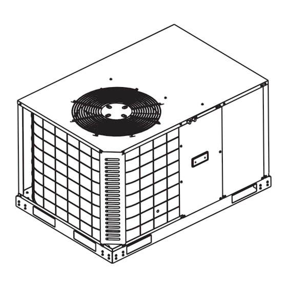
R-410A, 13 SEER NL024-060 SO 9001 Certified Quality 2-5 Ton Management System TABLE OF CONTENTS General ......... . 1 Installing Drain Tube And Connection . - Page 2 543173-BIM-A-1109 personnel should install, repair, or service this equipment. Untrained personnel can perform basic maintenance functions of cleaning coils and filters and replacing filters. This product must be installed in strict compliance with Observe all precautions in the literature, labels, and tags the installation instructions and any applicable local, accompanying the equipment whenever working on air state and national codes including, but not limited to...
-
Page 3: Installation
543173-BIM-A-1109 Installation Refer to Table 5 for unit physical data and to Table 4 for electrical data. Limitations If components are to be added to a unit to meet local codes, These units must be installed in accordance with the following they are to be installed at the dealer's and/or the customer's national and local safety codes. -
Page 4: Unit Location
543173-BIM-A-1109 Unit Location Relationship between building, sun and unit – If practical, place the air conditioner in an area where the unit and the Several important factors must be considered before selecting ducts will be shaded from the afternoon sun (when the heat the site for this unit: load is the greatest). -
Page 5: Clearances
543173-BIM-A-1109 Clearances All units require certain clearances for proper operation and service. Refer to Table 3 for the clearances required for construction, servicing and proper unit operation. Rear Left Right Front Figure 3: Unit 4 Point Load Weight Size Weight (lbs.) Center of Gravity 4 Point Load Location (lbs.) (Tons) -
Page 6: Unit Dimensions
543173-BIM-A-1109 HIGH VOLTAGE CONN. Ø7/8" KNOCKOUT HIGH VOLTAGE CONN. Ø1 3/32" KNOCKOUT HIGH VOLTAGE CONN. Ø1 3/8" 15-13/16 KNOCKOUT 13-9/16 CONDENSATE DRAIN 3/4" NPT LOW VOLTAGE CONN. Ø7/8" BUSHING 7-7/16 4-13/16 4-3/8 DUCT FLANGE ØG 1-15/16 2-9/16 Unit Dimensions Figure 4: Table 2: Unit Dimensions Size Dimensions... -
Page 7: Installing Of Duct To Unit (Manufactured Housing)
543173-BIM-A-1109 Table 3: Unit Clearances Distance Distance Direction Direction (in.) (in.) Right Front Left Rear Bottom 1. Units must be installed outdoors. Over hanging structure or shrubs should not obscure condenser air discharge outlet. 2. Unit may be positioned to draw air from underneath structure. Installing Of Duct To Unit... -
Page 8: Wye Insulation
543173-BIM-A-1109 When attaching the flex duct to the return air box, secure Insert a stub collar in the raw end of the duct and tape the duct collar and return box collar together with at least securely in place. three (3) sheet metal screws and seal with duct tape. Make sure the duct is not stretched tight and does not have Set the return air box, with flex duct attached, back into the kinks from excessive length after installation. -
Page 9: Discharge Duct Installation
543173-BIM-A-1109 Grille Filter Return Box Damper* Flex Duct Grille 12” Duct Connectors Filter Return Box Damper* Flex Duct Flex Duct WYE Insulation Recommended 12 x12 x12 12 x12 x12 for Greater Efficiency and Performance of Unit. May use duct connector without damper if no interior furnace or air handler is connected to duct system. -
Page 10: Installing Of Duct To Unit (Residential)
543173-BIM-A-1109 If using the duct connector with damper, cut a 9-1/8”x 16-1/8” (located in the front corner of the unit), and the drain tube hole in the center of the duct bottom. If using the 12” diameter installed on the barbed end of the plastic fitting secured in duct connector without damper cut a 12-1/8”... -
Page 11: Compressors
543173-BIM-A-1109 Compressors The compressor used in this product is specifically designed to operate with R-410A Refrigerant and cannot be interchanged. Do not loosen compressor mounting bolts. Power And Control Wiring This system uses R-410A Refrigerant which operates at Field wiring to the unit must conform to provisions of the current higher pressures than R-22. -
Page 12: Control Wiring
543173-BIM-A-1109 Control Wiring Run low voltage control circuit wires through the “fingered” snap bushing into the low voltage compartment. The heating side of this thermostat is equipped with a Connect low voltage wires from the thermostat to the red, self adjusting anticipator. Anticipator adjustment is not yellow and green 18 gauge wires in the unit low voltage needed and no provision is made for it. -
Page 13: Pre-Start Procedure
543173-BIM-A-1109 System Startup, Check-out Thermostat Cool Contacts Heat Cooling With the thermostat set to the “OFF” position, close Antic. Cooling disconnect switch or switches to complete circuit to air Antic. System conditioner. Set thermostat to call for cooling. Auto On Heat With the system in operation, check the air conditioner for unusual noise and undue vibration. -
Page 14: Ton
543173-BIM-A-1109 Table 4: Electrical Data OD Fan Supply Factory Compressors Motors Blower Electric Heat Option Size MOCP Fuse (each) Volt (each) Motor (Tons) (Amps) (Amps) Size (Amps) Model Stages Amps None – – – 14.9 2PH08520506 3.6/4.8 17.2/19.9 25.7/29.0 30/30 30/30 208/230-1-60 43.0... -
Page 15: Physical Data
543173-BIM-A-1109 Table 5: Physical Data Models Component NL024 NL030 NL036 NL042 NL048 NL060 Nominal Tonnage ARI COOLING PERFORMANCE Gross Capacity @ ARI A point (Btu) 24300 31500 37000 41400 48100 57500 ARI net capacity (Btu) 23300 30200 35400 40200 46500 55800 10.8 11.4... -
Page 16: Airflow Performance
543173-BIM-A-1109 Airflow Performance Table 6: Airflow Performance External Static Pressure (Inch Water Gauge) Size Unit Speed) (Tons) SCFM SCFM SCFM SCFM SCFM 1048 1008 1005 1056 1100 Medium 1273 1194 1028 1084 1064 1094 1119 (2.0) High 1410 1069 1302 1090 1160 1109... -
Page 17: Additional Static Resistance
543173-BIM-A-1109 Table 7: Additional Static Resistance Electric Heat, kW Size Wet Indoor Coil (Tons) 0.05 0.05 0.05 0.06 0.07 0.06 0.06 0.06 0.07 0.08 0.07 0.07 0.07 0.08 0.09 0.08 0.08 0.08 0.09 0.10 0.09 0.09 0.09 0.10 0.12 0.10 0.10 0.11 0.13... -
Page 18: Maintenance
543173-BIM-A-1109 Table 8: Electric Heat Minimum Supply Air Minimum Supply Air (CFM) Size Voltage Heater kW (Tons) 10.0 15.0 208/230-1-60 (2.0) 208/230-1-60 (2.5) 208/230-1-60 (3.0) 208/230-1-60 (3.5) 208/230-1-60 1300 1300 1270 1160 (4.0) 208/230-1-60 1300 1300 1270 1160 (5.0) Table 9: Indoor Blower Specifications Size Motor (Tons) -
Page 19: Typical Wiring Diagrams
543173-BIM-A-1109 Typical Wiring Diagrams NL024, 030 and 036 Typical Cooling Unit 208/230-1-60 volt Wiring Diagram Unitary Products Group... - Page 20 543173-BIM-A-1109 NL036 Typical Cooling Unit 208/230-3-60 volt Wiring Diagram Unitary Products Group...
- Page 21 543173-BIM-A-1109 NL042, 048 and 060 Typical Cooling Unit 208/230-1-60 volt Wiring Diagram Unitary Products Group...
- Page 22 543173-BIM-A-1109 NL048 and 060 Typical Cooling Unit 208/230-3-60 volt Wiring Diagram Unitary Products Group...
- Page 23 NL048 and 060 Typical Cooling Unit 460-3-60 volt Wiring Diagram Subject to change without notice. Printed in U.S.A. 543173-BIM-A-1109 Copyright © 2009 by Unitary Products Group. All rights reserved. Supersedes: Nothing Johnson Controls Unitary Products 5005 York Drive Norman, OK 73069...
Need help?
Do you have a question about the NL024-060 and is the answer not in the manual?
Questions and answers