Johnson Controls Unitary Products YH-07 Technical Manual
Split-system
air-cooled condensing units
and air handlers
yh-07 thru -25 and yj-10 thru -20
condensing unit models
ph-07 thru -15 and pj-15 thru -20
heat pump unit models
nh-07 thru -25 and nj-10 thru -20
air handling unit models
7.5 - 25 ton
60
Table of Contents
Advertisement
TECHNICAL
TECHNICAL
GUIDE
GUIDE
R-410A
SPLIT-SYSTEM
AIR-COOLED CONDENSING UNITS
AND AIR HANDLERS
YH-07 thru -25 and YJ-10 thru -20
CONDENSING UNIT MODELS
PH-07 thru -15 and PJ-15 thru -20
HEAT PUMP UNIT MODELS
NH-07 thru -25 and NJ-10 thru -20
AIR HANDLING UNIT MODELS
7.5 - 25 Ton
60 Hertz
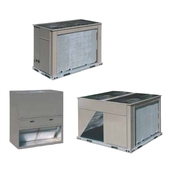
NH/NJ Indoor Units
Description
UP condensing units and heat pumps are completely assembled,
piped and wired at the factory to provide a single-piece unit for
shipment and rigging. Each unit is pressurized with a holding charge of
refrigerant R-410A for storage and/or shipping.
The compact design, clean styling, small footprint, and quiet operation
make these condensing units and heat pumps suitable for almost any
outdoor location. On rooftops... because they weigh much less than a
single package unit of similar capacity and are much easier to rig and
support. On the ground... because the footprint is compact allowing a
variety of applications.
Both the UP condensing units and heat pumps are equipped with
reliable Smart Equipment™ microprocessor controls to assure proper
operation and unit protection for long product life. Products from 10 to
20 tons are available in single or dual (2 or 4 pipe) refrigerant circuits
for redundancy in operation and various application choices such as
one outdoor unit matched with two indoor units.
The UP air handling units are completely assembled units, including a
well-insulated cabinet, a DX cooling coil with copper tubing, aluminum
fins, expansion valve(s), distributor(s), 2" throwaway filters, a
centrifugal blower, a blower motor, an adjustable belt drive, a blower
YH/YJ/PH Outdoor Units
motor contactor and a small
holding charge of nitrogen.
YH/YJ/PH/PJ Outdoor Units
505430-BTG-R-1016
(Except YH-25)
ISO 9001
Certified Quality
Management System
Advertisement
Table of Contents

Related Manuals for Johnson Controls Unitary Products YH-07


Summary of Contents for Johnson Controls Unitary Products YH-07
- Page 1 The compact design, clean styling, small footprint, and quiet operation make these condensing units and heat pumps suitable for almost any YH-07 thru -25 and YJ-10 thru -20 outdoor location. On rooftops... because they weigh much less than a CONDENSING UNIT MODELS single package unit of similar capacity and are much easier to rig and support.
- Page 2 An added benefit of the UP air handling units is they are heat pump applications. Johnson Controls Unitary Products...
-
Page 3: Table Of Contents
Weights And Dimensions ................88 Johnson Controls Unitary Products... -
Page 4: Nomenclature
2. NH/NJ-20 Airflow Option D = 3 HP Motor “F” Only. E = 5 HP Motor F = 7.5 HP Motor N = None (Motor Drive Kit Req) 1. Motors are not shipped with 25 ton Air Handler Units. Johnson Controls Unitary Products... -
Page 5: Condensing Unit Features And Benefits
These air handlers can be arranged for a variety of air maintenance or for service. discharge patterns in either the horizontal or vertical position. • Factory installed powered or non-powered 115 volt GFI Refer to the unit installation instructions for other application outlet. possibilities. Johnson Controls Unitary Products... - Page 6 The coil is Relay Kit. See details in Overload Relay Kit and Overload leak-tested at 325 psig and dried before the connections are Relay Setting Tables on Page 70. capped for storage and shipping. Johnson Controls Unitary Products...
-
Page 7: Guide Specifications
Split System Cooling Only Condensing Units • Exterior surfaces bonded and coated with baked Models: YH-07 thru -25, YJ-10 thru -20 & Split enamel finish by a powder paint process capable of System Heat Pump Models: PH-07 thru -15, PJ-15... -
Page 8: Cooling
Safety lockouts send a 24 volt signal to the control requirements, dimensions, operation and appearance. board's "X" terminal, allowing notification to the user via the thermostat fault light (if present). Johnson Controls Unitary Products... - Page 9 • Indoor unit shall be equipped with a V-belt drive option the CFM requirements of the air delivery system. (Refer that will permit the blower RPM to be adjusted to meet to Technical Guide for Airflow Capabilities.) Johnson Controls Unitary Products...
- Page 10 The Blower Wheels Shall: Be dynamically balanced to minimize the levels of sound and vibration generated by the unit. Johnson Controls Unitary Products...
-
Page 11: Physical Data
505430-BTG-R-1016 Physical Data YH-07 thru -25 and YJ-10 thru -20 Physical Data Models Component YH-07 YH-10 YJ-10 YH-12 YJ-12 YH-15 YJ-15 YH-20 YJ-20 YH-25 Nominal Tonnage 12.5 12.5 REFRIGERANT Refrigerant type R-410A R-410A R-410A R-410A R-410A R-410A R-410A R-410A R-410A... - Page 12 9800 Holding Charge is the amount in the unit as shipped from the factory. Includes matched evaporator unit with 25 ft of piping. All compressors include crankcase heaters. When viewing the shaft end of the motor. Johnson Controls Unitary Products...
- Page 13 FACE AREA (SQ. FT.) 11.1 11.1 11.1 20.0 20.0 22.2 22.2 16 x 25 x 4 Size and Quantity Per Model (In.) 20 x 24 x 4 FACE AREA (SQ. FT.) 11.1 11.1 11.1 18.0 18.0 22.2 22.2 Johnson Controls Unitary Products...
- Page 14 Fins per inch Tube diameter (Copper) (In.) Connection, (NPTE) (In.) Inlet Outlet 1-1/2 Weight (lb) Motors, Drive and Overload Kits must be ordered separately for the NH-25. The Motor Drive and Overload Kits are to be field installed. Johnson Controls Unitary Products...
-
Page 15: Unit Limitations
460-3-60 (20) 575-3-60 208/230-3-60 460-3-60 (25) 575-3-60 1. Rated in accordance with AHRI Standard 110, Range “A” Utilization Voltage. †. Low Ambient accessories are available to permit stable system operation at ambient temperatures down to 0°F. Johnson Controls Unitary Products... - Page 16 90/77 208/230-3-60 8,000 12,000 65/57 90/77 NH-25 460-3-60 8,000 12,000 65/57 90/77 575-3-60 8,000 12,000 65/57 90/77 Heating Min/Max temperatures apply to steam and hot water coils. NOTE: Do not apply steam to hot water coils. Johnson Controls Unitary Products...
-
Page 17: Cooling And Heating Ratings
Gross capacity does not include heat added by blower motor. Refer to appropriate table for blower horsepower. Heat Pumps designed for matched systems only. LEGEND EER = Energy Efficiency Ratio AHRI = Air Conditioning and Refrigeration Institute IPLV = Integration Part-Load Value IEER = Integrated Energy Efficiency Ratio Johnson Controls Unitary Products... -
Page 18: Capacity Performance
49.1 89.7 89.7 87.9 75.3 61.4 47.4 3750 86.1 86.1 86.1 86.1 72.3 58.4 44.5 82.1 82.1 82.1 82.1 68.2 54.3 40.4 87.1 87.1 87.1 87.1 73.2 59.4 45.5 83.0 83.0 83.0 83.0 69.1 55.2 41.2 Johnson Controls Unitary Products... - Page 19 Performance Table for the BHP of the supply air blower motor, MBh = 3.415 x kW and kW = BHP x 0.746 nameplate rated motor efficiency. These ratings include the condenser fan motors and the compressor motors but not the supply air blower motor. Johnson Controls Unitary Products...
-
Page 20: Btg-R
126.1 120.4 102.1 82.5 62.9 5000 127.0 127.0 127.0 127.0 107.9 88.8 69.7 118.5 10.5 118.5 118.5 118.5 99.0 79.4 59.8 125.6 125.6 125.6 125.6 106.5 87.4 68.3 117.8 10.6 117.8 117.8 117.8 98.2 78.7 59.1 Johnson Controls Unitary Products... -
Page 21: Btg-R
Performance Table for the BHP of the supply air blower motor, MBh = 3.415 x kW and kW = BHP x 0.746 nameplate rated motor efficiency. These ratings include the condenser fan motors and the compressor motors but not the supply air blower motor. Johnson Controls Unitary Products... - Page 22 125.0 118.9 99.9 81.0 62.0 5000 122.2 122.2 122.2 122.2 103.5 84.9 66.2 115.0 10.5 115.0 115.0 115.0 96.1 77.1 58.1 125.7 125.7 125.7 125.7 107.0 88.4 69.7 118.7 10.5 118.7 118.7 118.7 99.8 80.8 61.8 Johnson Controls Unitary Products...
- Page 23 Performance Table for the BHP of the supply air blower motor, MBh = 3.415 x kW and kW = BHP x 0.746 nameplate rated motor efficiency. These ratings include the condenser fan motors and the compressor motors but not the supply air blower motor. Johnson Controls Unitary Products...
- Page 24 125.2 100.4 75.6 6250 146.0 11.9 146.0 146.0 146.0 121.3 96.5 71.8 142.2 13.6 142.2 142.2 142.2 117.5 92.7 67.9 151.8 12.0 151.8 151.8 151.8 127.0 102.3 77.6 146.8 13.7 146.8 146.8 146.8 122.0 97.2 72.5 Johnson Controls Unitary Products...
- Page 25 Performance Table for the BHP of the supply air blower motor, MBh = 3.415 x kW and kW = BHP x 0.746 nameplate rated motor efficiency. These ratings include the condenser fan motors and the compressor motors but not the supply air blower motor. Johnson Controls Unitary Products...
- Page 26 131.2 106.1 81.0 6250 152.7 11.7 152.7 152.7 152.7 127.7 102.8 77.8 144.3 13.2 144.3 144.3 144.3 119.2 94.1 69.0 155.6 11.7 155.6 155.6 155.6 130.6 105.6 80.6 147.8 13.3 147.8 147.8 147.8 122.7 97.6 72.5 Johnson Controls Unitary Products...
- Page 27 Performance Table for the BHP of the supply air blower motor, MBh = 3.415 x kW and kW = BHP x 0.746 nameplate rated motor efficiency. These ratings include the condenser fan motors and the compressor motors but not the supply air blower motor. Johnson Controls Unitary Products...
- Page 28 154.3 126.5 98.6 7500 181.9 17.0 181.9 181.9 181.9 154.1 126.4 98.6 167.9 17.0 167.9 167.9 167.9 140.1 112.2 84.4 182.2 17.0 182.2 182.2 182.2 154.4 126.7 99.0 169.0 17.0 169.0 169.0 169.0 141.2 113.4 85.6 Johnson Controls Unitary Products...
- Page 29 Performance Table for the BHP of the supply air blower motor, MBh = 3.415 x kW and kW = BHP x 0.746 nameplate rated motor efficiency. These ratings include the condenser fan motors and the compressor motors but not the supply air blower motor. Johnson Controls Unitary Products...
- Page 30 160.2 131.7 103.3 7500 184.1 14.4 184.1 184.1 184.1 156.5 128.9 101.3 177.4 16.3 177.4 177.4 177.4 149.0 120.5 92.1 186.7 14.5 186.7 186.7 186.7 159.1 131.5 103.9 179.8 16.3 179.8 179.8 179.8 151.4 122.9 94.5 Johnson Controls Unitary Products...
- Page 31 Performance Table for the BHP of the supply air blower motor, MBh = 3.415 x kW and kW = BHP x 0.746 nameplate rated motor efficiency. 2. These ratings include the condenser fan motors and the compressor motors but not the supply air blower motor. Johnson Controls Unitary Products...
- Page 32 184.0 148.9 113.9 10000 235.6 17.5 235.6 235.6 230.6 196.2 161.7 127.3 222.8 19.8 222.8 222.8 220.3 185.3 150.3 115.2 231.4 17.5 231.4 231.4 231.4 196.9 162.5 128.1 221.9 19.9 221.9 221.9 221.9 186.9 151.8 116.8 Johnson Controls Unitary Products...
- Page 33 Performance Table for the BHP of the supply air blower motor, MBh = 3.415 x kW and kW = BHP x 0.746 nameplate rated motor efficiency. These ratings include the condenser fan motors and the compressor motors but not the supply air blower motor. Johnson Controls Unitary Products...
- Page 34 184.0 148.2 112.3 10000 237.6 18.0 237.6 237.6 234.9 199.1 163.3 127.5 227.5 20.3 227.5 227.5 226.1 190.3 154.5 118.6 232.1 18.0 232.1 232.1 232.1 196.3 160.5 124.7 223.6 20.3 223.6 223.6 223.6 187.7 151.9 116.1 Johnson Controls Unitary Products...
- Page 35 Performance Table for the BHP of the supply air blower motor, MBh = 3.415 x kW and kW = BHP x 0.746 nameplate rated motor efficiency. These ratings include the condenser fan motors and the compressor motors but not the supply air blower motor. Johnson Controls Unitary Products...
- Page 36 260.5 211.3 162.2 12500 311.8 24.7 311.8 311.8 311.8 263.3 214.7 166.2 289.5 27.4 289.5 289.5 289.5 240.4 191.2 142.1 314.6 24.5 314.6 314.6 314.6 266.1 217.6 169.0 297.6 27.2 297.6 297.6 297.6 248.5 199.3 150.2 Johnson Controls Unitary Products...
- Page 37 Performance Table for the BHP of the supply air blower motor, MBh = 3.415 x kW and kW = BHP x 0.746 nameplate rated motor efficiency. These ratings include the condenser fan motors and the compressor motors but not the supply air blower motor. Johnson Controls Unitary Products...
- Page 38 23.1 10.2 25.6 27.9 YH-25 18.4 19.0 20.0 16.0 21.4 13.6 23.7 11.4 26.3 28.8 18.9 20.4 20.6 17.3 22.2 14.8 24.2 12.6 27.1 10.4 29.7 19.5 21.8 21.3 18.5 22.9 16.0 24.8 13.7 27.8 11.2 30.7 Johnson Controls Unitary Products...
- Page 39 54.4 90.1 90.1 89.4 79.9 65.9 52.0 3750 89.8 89.8 89.8 89.8 75.9 62.0 48.1 84.4 84.4 84.4 84.4 70.4 56.4 42.4 90.4 90.4 90.4 90.4 76.5 62.6 48.7 84.4 84.4 84.4 84.4 70.5 56.5 42.5 Johnson Controls Unitary Products...
- Page 40 Performance Table for the BHP of the supply air blower motor, MBh = 3.415 x kW and kW = BHP x 0.746 nameplate rated motor efficiency. These ratings include the condenser fan motors and the compressor motors but not the supply air blower motor. Johnson Controls Unitary Products...
- Page 41 118.0 115.5 101.5 82.6 63.8 5000 119.0 119.0 119.0 119.0 100.5 82.0 63.5 112.9 10.7 112.9 112.9 112.9 94.1 75.2 56.4 125.8 125.8 125.8 125.8 107.3 88.8 70.3 117.0 10.7 117.0 117.0 117.0 98.2 79.4 60.5 Johnson Controls Unitary Products...
- Page 42 Performance Table for the BHP of the supply air blower motor, MBh = 3.415 x kW and kW = BHP x 0.746 nameplate rated motor efficiency. These ratings include the condenser fan motors and the compressor motors but not the supply air blower motor. Johnson Controls Unitary Products...
- Page 43 150.7 121.9 93.1 7500 174.3 14.4 174.3 174.3 174.3 145.5 116.7 87.9 161.5 16.2 161.5 161.5 161.5 132.7 103.9 75.1 179.2 14.5 179.2 179.2 179.2 150.4 121.6 92.8 166.8 16.2 166.8 166.8 166.8 138.1 109.3 80.5 Johnson Controls Unitary Products...
- Page 44 Performance Table for the BHP of the supply air blower motor, MBh = 3.415 x kW and kW = BHP x 0.746 nameplate rated motor efficiency. These ratings include the condenser fan motors and the compressor motors but not the supply air blower motor Johnson Controls Unitary Products...
- Page 45 147.1 118.3 89.6 7500 172.4 14.4 172.4 172.4 172.4 144.1 115.7 87.4 160.1 16.3 160.1 160.1 160.1 131.4 102.6 73.9 173.7 14.5 173.7 173.7 173.7 145.3 117.0 88.7 162.3 16.4 162.3 162.3 162.3 133.5 104.8 76.0 Johnson Controls Unitary Products...
- Page 46 Performance Table for the BHP of the supply air blower motor, MBh = 3.415 x kW and kW = BHP x 0.746 nameplate rated motor efficiency. These ratings include the condenser fan motors and the compressor motors but not the supply air blower motor. Johnson Controls Unitary Products...
- Page 47 177.9 141.2 104.6 10000 231.2 18.6 231.2 231.2 227.3 190.8 154.2 117.6 216.8 20.8 216.8 216.8 214.9 178.2 141.5 104.8 236.4 18.7 236.4 236.4 232.5 195.9 159.3 122.7 223.9 21.0 223.9 223.9 220.6 183.9 147.2 110.5 Johnson Controls Unitary Products...
- Page 48 Performance Table for the BHP of the supply air blower motor, MBh = 3.415 x kW and kW = BHP x 0.746 nameplate rated motor efficiency. These ratings include the condenser fan motors and the compressor motors but not the supply air blower motor. Johnson Controls Unitary Products...
- Page 49 These capacities do not include the supply air blower motor heat. For net capacity, add motor heat, MBh. Blower Performance Table for the BHP of the supply air blower motor, MBh = 3.415 x kW and kW = BHP x 0.746 nameplate rated motor efficiency. Johnson Controls Unitary Products...
- Page 50 These capacities do not include the supply air blower motor heat. For net capacity, add motor heat, MBh. Blower Performance Table for the BHP of the supply air blower motor, MBh = 3.415 x kW and kW = BHP x 0.746 nameplate rated motor efficiency. Johnson Controls Unitary Products...
- Page 51 These capacities do not include the supply air blower motor heat. For net capacity, add motor heat, MBh. Blower Performance Table for the BHP of the supply air blower motor, MBh = 3.415 x kW and kW = BHP x 0.746 nameplate rated motor efficiency. Johnson Controls Unitary Products...
-
Page 52: Air Handling And Hot Water Coil Accessory Heating Capacity
These capacities do not include any blower motor heat. Steam Coil Capacity Correction Factors For High Steam Pressure STEAM PRESSURE (PSIG) CAPACITY CORRECTION FACTOR 1.05 1.12 1.19 1.25 1.30 NOTE: Steam Rate = (lbs/Hr.) = 1.025 x MBH Johnson Controls Unitary Products... -
Page 53: Airflow Performance
1. Airflow performance includes dry evaporator coil. See Static Resistance table for additional applications. 2. See RPM Selection table to determine desired motor sheave setting and to determine the maximum continuous BHP. 3. kW = BHP x 0.746 ÷ nameplate rated motor efficiency. Johnson Controls Unitary Products... - Page 54 1. Airflow performance includes dry evaporator coil. See Static Resistance table for additional applications. 2. See RPM Selection table to determine desired motor sheave setting and to determine the maximum continuous BHP. 3. kW = BHP x 0.746 ÷ nameplate rated motor efficiency. Johnson Controls Unitary Products...
- Page 55 1. Airflow performance includes dry evaporator coil. See Static Resistance table for additional applications. 2. See RPM Selection table to determine desired motor sheave setting and to determine the maximum continuous BHP. 3. kW = BHP x 0.746 ÷ nameplate rated motor efficiency. Johnson Controls Unitary Products...
- Page 56 1. Airflow performance includes dry evaporator coil. See Static Resistance table for additional applications. 2. See RPM Selection table to determine desired motor sheave setting and to determine the maximum continuous BHP. 3. kW = BHP x 0.746 ÷ nameplate rated motor efficiency. Johnson Controls Unitary Products...
-
Page 57: Hp Motor And Drive
4.2 - 5.2 0.875 AK84 1.000 48.3 Std. 56HZ 1VP50 565 - 721 3.6 - 4.6 0.875 AK114 11.0 1.000 45.3 NH/NJ-15 1725 1.15 184T 2VP50 707 - 894 3.7 - 4.7 1.125 2B5V94 1.000 41.8 Johnson Controls Unitary Products... - Page 58 Motors with Service Factor of 1.15 or Greater: Adjust overload relay dial to the motor nameplate Full Load Amps (FLA). Motors with Service Factor Less Than 1.15: Adjust overload relay dial based on the formula: Motor nameplate FLA x 0.90 = relay setting Johnson Controls Unitary Products...
- Page 59 0.01 0.22 0.13 0.04 0.08 0.12 9500 0.00 0.23 0.00 0.04 0.08 0.13 9750 0.00 0.24 0.00 0.04 0.09 0.13 10000 0.00 0.25 0.00 0.04 0.09 0.14 Pressure drop added by condensate over a dry coil. Johnson Controls Unitary Products...
- Page 60 As the altitude application at sea level. Air density correction factors are or temperature increases, the density of air decreases. In shown in Altitude Factors Table and Temperature Correction Figure. Johnson Controls Unitary Products...
- Page 61 6,000 CFM if the rpm is unchanged. However, the blower tables to select the blower speed and the BHP Altitude/Temperature Correction Factors table must be used to requirement. determine the static pressure and BHP. Since no temperature Johnson Controls Unitary Products...
- Page 62 The first step is to convert this static pressure to equivalent This value must be corrected for elevation. sea level conditions. BHP at 5,000 ft. = 3.2 x .832 = 2.66 Sea level static pressure = 1.5 / .832 = 1.80" Johnson Controls Unitary Products...
- Page 63 Motor Blower 6 Turns 5 Turns 4 Turns 3 Turns 2 Turns 1 Turn Fully Unit Model Sheave Sheave Open Open Open Open Open Open Closed Std. 1.73 1VL40 AK69 2.30 1VL40 AK56 1062 1128 1194 Johnson Controls Unitary Products...
-
Page 64: Sound Performance
Sound Model (Tons) Rating 1000 2000 4000 8000 PH-07 (7.5) YH-07 PH-10 YH-10 (10.0) YJ-10 YH-12 (12.5) YJ-12 PH-15 PJ-15 (15.0) YH-15 YJ-15 PJ-20 YH-20 (20.0) YJ-20 YH-25 (25.0) Rated in accordance with AHRI 270 Standard. Johnson Controls Unitary Products... -
Page 65: Electrical Data
Based on three, 75°C insulated copper conductors in conduit and ambient of 30°C. Maximum fuse or maximum circuit breaker (HACR type per NEC). Refer to NEC/NFPA No. 70, Articles 440-11, 12 for information on minimum disconnect sizing. Johnson Controls Unitary Products... - Page 66 Based on three, 75°C insulated copper conductors in conduit and ambient of 30°C. Maximum fuse or maximum circuit breaker (HACR type per NEC). Refer to NEC/NFPA No. 70, Articles 440-11, 12 for information on minimum disconnect sizing. Johnson Controls Unitary Products...
- Page 67 Based on three, 75°C insulated copper conductors in conduit and ambient of 30°C. Maximum fuse or maximum circuit breaker (HACR type per NEC). Refer to NEC/NFPA No. 70, Articles 440-11, 12 for information on minimum disconnect sizing. Johnson Controls Unitary Products...
- Page 68 None 10 KW 12.0 19.3 460-3-60 16 KW 19.2 28.3 26 KW 31.3 43.3 36 KW 43.3 58.4 None 10 KW 15.0 575-3-60 16 KW 15.4 22.2 26 KW 25.0 34.3 36 KW 34.6 46.3 NH-10C00C Johnson Controls Unitary Products...
- Page 69 36 KW 86.6 118.5 None 10 KW 20.2 460-3-60 16 KW 19.2 29.2 26 KW 31.3 44.2 36 KW 43.3 59.3 None 10 KW 16.3 575-3-60 16 KW 15.4 23.5 26 KW 35.5 36 KW 34.6 47.6 Johnson Controls Unitary Products...
- Page 70 19.2 32.8 460-3-60 26 KW 31.3 47.8 36 KW 43.3 62.9 50 KW 60.1 68.9 None 10 KW 18.5 16 KW 15.4 25.7 575-3-60 26 KW 25.0 37.8 36 KW 34.6 49.8 50 KW 48.1 54.6 Johnson Controls Unitary Products...
- Page 71 None 28.0 460-3-60 11.0 None 14.0 575-3-60 None Minimum Circuit Ampacity. Dual Element, Time Delay Type. HACR type per NEC. NH/NJ-15C00D Models Only Motors are not shipped with these models. Motor and Drive Kits are required. Johnson Controls Unitary Products...
-
Page 72: Typical Wiring Diagrams
505430-BTG-R-1016 Typical Wiring Diagrams Air Conditioning Condensing Units Typical YH-07 Wiring Diagram Johnson Controls Unitary Products... - Page 73 505430-BTG-R-1016 Typical YH-10 thru -12 Wiring Diagram Johnson Controls Unitary Products...
- Page 74 505430-BTG-R-1016 Typical YJ-10 thru -12 Wiring Diagram Johnson Controls Unitary Products...
- Page 75 505430-BTG-R-1016 Typical YH-15 Wiring Diagram Johnson Controls Unitary Products...
- Page 76 505430-BTG-R-1016 Johnson Controls Unitary Products...
- Page 77 505430-BTG-R-1016 Typical YH-20 Wiring Diagram Johnson Controls Unitary Products...
- Page 78 505430-BTG-R-1016 Typical YH-25 Wiring Diagram Johnson Controls Unitary Products...
- Page 79 505430-BTG-R-1016 Typical YJ-15 thru -20 Wiring Diagram Johnson Controls Unitary Products...
- Page 80 505430-BTG-R-1016 Heat Pump Units Typical PH-07 Wiring Diagram Johnson Controls Unitary Products...
- Page 81 505430-BTG-R-1016 Typical PH-10 Wiring Diagram Johnson Controls Unitary Products...
- Page 82 505430-BTG-R-1016 Typical PH-15 Wiring Diagram Johnson Controls Unitary Products...
- Page 83 505430-BTG-R-1016 Typical PJ-15 thru -20 Wiring Diagram Johnson Controls Unitary Products...
- Page 84 505430-BTG-R-1016 Air Handling Units Typical NH-07 Wiring Diagram Johnson Controls Unitary Products...
- Page 85 505430-BTG-R-1016 Typical NH-10 thru -20, 1.5 thru 5 HP Blower Motor Only Wiring Diagram Johnson Controls Unitary Products...
- Page 86 505430-BTG-R-1016 Typical NH-20, 7.5 HP Blower Motor 208/230 V Only Wiring Diagram Johnson Controls Unitary Products...
- Page 87 505430-BTG-R-1016 Typical NH-20, 7.5 HP Blower Motor 460/575 V Only Wiring Diagram Johnson Controls Unitary Products...
- Page 88 505430-BTG-R-1016 Typical NH-25 Wiring Diagram Johnson Controls Unitary Products...
- Page 89 505430-BTG-R-1016 Typical NJ-20, 1.5 Thru 5 HP Blower Motor Only Wiring Diagram Johnson Controls Unitary Products...
- Page 90 505430-BTG-R-1016 Typical NJ-20, 7.5 HP Blower Motor 208/230 V Only Wiring Diagram Johnson Controls Unitary Products...
- Page 91 505430-BTG-R-1016 Johnson Controls Unitary Products...
- Page 92 505430-BTG-R-1016 Typical NJ-20, 7.5 HP Blower Motor 460/575 V Only Wiring Diagram Johnson Controls Unitary Products...
- Page 93 505430-BTG-R-1016 Johnson Controls Unitary Products...
-
Page 94: Weights And Dimensions
DIM Y LENGTH RIGHT PC090, PC120, DIM Y YC090, YC120, YD120, YC150, YD150 LENGTH RIGHT PC180, PD180, PD240, YC180, YD180, YC240, YD240, YC300 NOTE: Front of unit is considered the side having the unit control box. Johnson Controls Unitary Products... - Page 95 15.53 12.70 12.000 SYSTEM 1 10.000 4.875 6.26 4.132 7.52 2.382 8.98 REAR LEFT 1.882 10.60 Unit Dimensions PH-07, PH-10, YH-07, YH/YJ-10, YH/YJ-12 Unit Height Dimensions MODEL PH-07 44.5 PH-10 50.0 YH-07 44.5 YH-10 50.0 YJ-10 50.0 YH-12 50.0 YJ-12 50.0...
-
Page 96: Johnson Controls Unitary Products
7.000 23.000 7.000 7.000 23.000 7.000 3.913 37.000 2.923 37.000 3.181 64.000 1.913 59.000 3.563 FRONT RIGHT SYSTEM 2 SYSTEM 1 16.133 13.133 17.367 18.867 20.617 22.617 FRONT (PIPING DETAIL) Unit Dimensions PH/PJ-15, PH/PJ-20, YH/YJ-15, YH/YJ-20 Johnson Controls Unitary Products... -
Page 97: Suction Line Od (In.) 2
1 5/8 1 1/8 1 5/8 1 3/8 1 5/8 Liquid Line OD (in.) Power Wiring Knockout 1 3/8 1 3/8 1 3/8 1 3/8 1 3/8 1 3/8 1 3/8 1 3/8 Control Wiring Knockout Johnson Controls Unitary Products... - Page 98 High Static Mtr. and Drv. 30.6 42.4 126 130 133 176 171 167 LEFT LEFT WIDTH WIDTH FRONT REAR REAR FRONT DIM Y DIM Y DIM X DIM X LENGTH LENGTH RIGHT HORIZONTAL POSITION RIGHT VERTICAL POSITION Johnson Controls Unitary Products...
- Page 99 220 204 180 160 172 194 NH-25 137.8 1067 1157 35.4 45.1 225 210 185 164 176 198 D (E) (D) C D (E) (D) C A (A) (B) B A (A) (B) B Vertical Horizontal Johnson Controls Unitary Products...
- Page 100 SYSTEM 1 13.13 10.73 2.000 DRAIN 3/4” ABS 1.88 PIPE CONNECTION 52.000 2.000 7.12 30.00 56.000 FRONT VIEW - RETURN AIR RIGHT SIDE VIEW - DRAIN PIPING/CONTROLS NH-07/-10 & NJ-10 INDOOR Unit Dimensions NH-07/-10 and NJ-10 Johnson Controls Unitary Products...
- Page 101 505430-BTG-R-1016 BOTTOM VIEW 2.72 50.75 2.72 2.66 AIR IN 11.43 30.00 HORIZONTAL CONFIGURATION 30.00 35.00 30.00 60.00 Unit Dimensions NH-07/-10 and NJ-10 (Continued) Johnson Controls Unitary Products...
- Page 102 SYSTEM 2 17.85 15.50 SYSTEM 1 13.13 10.73 2.00 DRAIN 3/4” ABS 1.88 70.50 2.00 PIPE CONNECTION 7.12 74.50 33.00 FRONT VIEW - RETURN AIR RIGHT SIDE VIEW - DRAIN PIPING/CONTROLS NH/NJ-15 INDOOR Unit Dimensions NH/NJ-15 Johnson Controls Unitary Products...
- Page 103 505430-BTG-R-1016 BOTTOM VIEW 74.50 2.72 69.25 2.72 2.66 AIR IN 14.43 33.00 HORIZONTAL CONFIGURATION 33.000 42.000 33.000 66.000 Unit Dimensions NH/NJ-15 (Continued) Johnson Controls Unitary Products...
- Page 104 19.19 15.50 SYSTEM 1 13.13 10.73 2.56 1.88 7.12 3.56 44.91 DRAIN 3/4” ABS PIPE CONNECTION 2.56 93.37 30.00 98.50 FRONT VIEW - RETURN AIR RIGHT SIDE VIEW - DRAIN PIPING/CONTROLS NH/NJ-20 INDOOR Unit Dimensions NH/NJ-20 Johnson Controls Unitary Products...
- Page 105 505430-BTG-R-1016 BOTTOM VIEW 98.50 2.72 45.38 50.59 45.38 2.72 2.66 AIR IN AIR IN 11.43 30.00 HORIZONTAL CONFIGURATION 30.00 35.00 30.00 60.00 Unit Dimensions NH/NJ-20 (Continued) Johnson Controls Unitary Products...
- Page 106 505430-BTG-R-1016 BLOWER EVAPORATOR POSITION POSITION POSITION POSITION COIL POSITION POSITION POSITION POSITION Vertical Airflow Arrangements NH-07 thru -20 and NJ-10 thru -20 Johnson Controls Unitary Products...
- Page 107 505430-BTG-R-1016 POSITION POSITION POSITION POSITION POSITION POSITION POSITION POSITION Horizontal Airflow Arrangements NH-07 thru -20 and NJ-10 thru -20 Johnson Controls Unitary Products...
- Page 108 33.22 Ø 2.13 SUCTION CONNECTION Ø 1.38 KO 24.98 Ø 0.88 DRAIN CONNECTION 7.64 3.53 2.36 3.37 46.97 0.63 4.08 95.59 4.22 100.13 38.06 FRONT (RETURN AIR) VIEW RIGHT SIDE (SERVICE CONNECTION) VIEW Unit Dimensions NH-25 Johnson Controls Unitary Products...
- Page 109 505430-BTG-R-1016 HORIZONTAL CONFIGURATION RETURN SUPPLY 73.3 74.0 Unit Dimensions NH-25 (Continued) BLOWER EVAPORATOR COIL Vertical Airflow Arrangements NH-25 NOTE: *If required, some air can be returned through the bottom of the evaporator section Johnson Controls Unitary Products...
- Page 110 Allow enough clearance to trap the condensate drain line. Note: If the coil has to be removed, the blower section can be unbolted and set aside and the coil can be lifted out the top of the evaporator section. Johnson Controls Unitary Products...
- Page 111 END VIEW MOUNTING DETAIL All Thread Steel Rod Mounting Bracket Flat Washer / Lock Washer and Nut Steel C- channel SIDE VIEW Typical Suspension of AHU’s From Ceiling Johnson Controls Unitary Products...
- Page 112 After these bottom channels are cut per Note 1, a new hole will have to be drilled at the cut end if the unit is to be mounted on isolators. Typical Suspension of NH-25 Unit Mounting Dimensions- NH-25 DIMENSIONS, INCHES UNIT 69-1/4 49-1/16 26-5/8 NH-25 Johnson Controls Unitary Products...
- Page 113 C S1 S2 G1 G2 66 60 X THERMOSTAT SINGLE STAGE COOL TWO STAGE HEAT EVAPORATOR CONTROL BOX Note: Do Not Use a heat Pump Thermostat Typical Simplified Field Wiring Diagram – NH-07 Evaporator with PH-07 Heat Pump Condenser Johnson Controls Unitary Products...
- Page 114 505430-BTG-R-1016 UNIT POWER SUPPLY Typical Simplified Field Wiring Diagram – NH-07 Evaporator Johnson Controls Unitary Products...
- Page 115 Thermostat Typical Simplified Field Wiring Diagram – NH-10 thru -20 Evaporator with PH-10 thru -20 Heat Pump Condenser VALVE SYS 2 218 / BR 1LLS 219 / Y Typical NH-10 thru -20 Liquid Line Solenoid Wiring Johnson Controls Unitary Products...
- Page 116 UNIT POWER SUPPLY Typical Simplified Field Wiring Diagram – NH-10 thru -20 Evaporator Subject to change without notice. Printed in U.S.A. 505430-BTG-R-1016 Copyright © 2016 by Johnson Controls, Inc. All rights reserved. Supersedes: 505430-BTG-Q-0816 York International Corporation 5005 York Drive Norman, OK 73069...
- Page 117 TWO STAGE COOL TWO STAGE HEAT EVAPORATOR CONTROL BOX Note: Do Not Use a heat Pump Thermostat Typical Simplified Field Wiring Diagram – NJ-15 thru -20 Evaporator with PJ-15 thru -20 Heat Pump Condenser UNIT POWER SUPPLY Johnson Controls Unitary Products...
- Page 118 505430-BTG-R-1016 Typical Simplified Field Wiring Diagram – NJ-15 thru -20 Evaporator Johnson Controls Unitary Products...
- Page 119 C S1 S2 G1 G2 66 60 X THERMOSTAT SINGLE STAGE COOL TWO STAGE HEAT EVAPORATOR CONTROL BOX Typical Simplified Field Wiring Diagram – NH-07 Evaporator with YH-07 Condenser UNIT POWER SUPPLY Typical Simplified Field Wiring Diagram – YH-07 Evaporator...
- Page 120 NOTE: On non NH/NJ Evaporator models, isolation relays must be installed to avoid overloading on 75 VA transformers on the condensing unit. VALVE SYS 2 218 / BR 1LLS 219 / Y Typical NH-10 thru -20 Liquid Line Solenoid Wiring Johnson Controls Unitary Products...
- Page 121 505430-BTG-R-1016 UNIT POWER SUPPLY Typical Simplified Field Wiring Diagram – NH-10 thru -20 Evaporator Johnson Controls Unitary Products...
- Page 122 NOTE: On non NH/NJ Evaporator models, isolation relays must be installed to avoid overloading on 75 VA transformers on the condensing unit. VALVE SYS 2 218 / BR 1LLS 219 / Y Typical NH-25 Liquid Line Solenoid Wiring Johnson Controls Unitary Products...
- Page 123 505430-BTG-R-1016 Typical Field Wiring Diagram - NH-25 Evaporator Johnson Controls Unitary Products...
- Page 124 Typical Simplified Field Wiring Diagram – NJ-10 thru -20 Evaporator with YJ-10 thru -20 Condenser NOTE: On non NH/NJ Evaporator models, isolation relays must be installed to avoid overloading on 75 VA transformers on the condensing unit. UNIT POWER SUPPLY Typical Simplified Field Wiring Diagram – NJ-10 thru -20 Evaporator Johnson Controls Unitary Products...
Need help?
Do you have a question about the YH-07 and is the answer not in the manual?
Questions and answers