Table of Contents
Advertisement
Quick Links
INSTALLATION MANUAL
SINGLE PACKAGE
AIR CONDITIONER / GAS HEAT
MODELS: PCG4 Series
3 - 5 Tons - 3 Phase - 460V
GENERAL INFORMATION . . . . . . . . . . . . . . . . . . . . . . . . . . . . . . . . 1
SAFETY . . . . . . . . . . . . . . . . . . . . . . . . . . . . . . . . . . . . . . . . . . . . . . . 1
MODEL NUMBER NOMENCLATURE . . . . . . . . . . . . . . . . . . . . . . . 2
INSTALLATION . . . . . . . . . . . . . . . . . . . . . . . . . . . . . . . . . . . . . . . . . 2
Component Location . . . . . . . . . . . . . . . . . . . . . . . . . . . . . . . . . . . . . 3
Center of Gravity Location . . . . . . . . . . . . . . . . . . . . . . . . . . . . . . . . . 4
Unit Dimensions . . . . . . . . . . . . . . . . . . . . . . . . . . . . . . . . . . . . . . . . . 5
Bottom Duct Dimensions (inches) . . . . . . . . . . . . . . . . . . . . . . . . . . . 6
Rear Duct Dimensions (inches) . . . . . . . . . . . . . . . . . . . . . . . . . . . . . 6
Typical Field Power Wiring Diagram . . . . . . . . . . . . . . . . . . . . . . . . . 7
Unit Limitations . . . . . . . . . . . . . . . . . . . . . . . . . . . . . . . . . . . . . . . . . . 3
Weights and Dimensions -Three-phase models . . . . . . . . . . . . . . . . 4
Unit Dimensions . . . . . . . . . . . . . . . . . . . . . . . . . . . . . . . . . . . . . . . . . 5
Unit Clearances, . . . . . . . . . . . . . . . . . . . . . . . . . . . . . . . . . . . . . . . . . 5
Electrical Data . . . . . . . . . . . . . . . . . . . . . . . . . . . . . . . . . . . . . . . . . . 7
Physical Data . . . . . . . . . . . . . . . . . . . . . . . . . . . . . . . . . . . . . . . . . . . 8
Natural Gas Pipe Sizing Chart . . . . . . . . . . . . . . . . . . . . . . . . . . . . . . 9
Propane (LP) Gas Pipe Sizing Chart . . . . . . . . . . . . . . . . . . . . . . . . . 9
SECTION I: GENERAL INFORMATION
These are electric cooling/gas heating units designed for outdoor instal-
lation. Only gas piping, electric power and duct connections are
required at the point of installation.
The gas-fired heaters have spark ignition.
The refrigerant system is fully charged with R-410A Refrigerant, and is
tested and factory sealed.
SECTION II: SAFETY
This is a safety alert symbol. When you see this symbol on
labels or in manuals, be alert to the potential for personal
injury.
Understand and pay particular attention to the signal words DANGER,
WARNING, or CAUTION.
DANGER indicates an imminently hazardous situation, which, if not
avoided, will result in death or serious injury.
WARNING indicates a potentially hazardous situation, which, if not
avoided, could result in death or serious injury.
CAUTION indicates a potentially hazardous situation, which, if not
avoided may result in minor or moderate injury. It is also used to
alert against unsafe practices and hazards involving only property dam-
age.
Johnson Controls Unitary Products
LIST OF SECTIONS
AIRFLOW PERFORMANCE . . . . . . . . . . . . . . . . . . . . . . . . . . . . . . 12
OPERATION . . . . . . . . . . . . . . . . . . . . . . . . . . . . . . . . . . . . . . . . . . 14
TYPICAL WIRING DIAGRAMS . . . . . . . . . . . . . . . . . . . . . . . . . . . . 18
START UP SHEET . . . . . . . . . . . . . . . . . . . . . . . . . . . . . . . . . . . . . . 21
LIST OF FIGURES
Flue Vent Outlet Air Hood . . . . . . . . . . . . . . . . . . . . . . . . . . . . . . . . . 10
Gas Valve . . . . . . . . . . . . . . . . . . . . . . . . . . . . . . . . . . . . . . . . . . . . . 16
Measuring External Static Pressure . . . . . . . . . . . . . . . . . . . . . . . . . 17
Connection Wiring Diagram . . . . . . . . . . . . . . . . . . . . . . . . . . . . . . . 18
Ladder Wiring Diagram . . . . . . . . . . . . . . . . . . . . . . . . . . . . . . . . . . . 19
R-410A Quick Reference Guide . . . . . . . . . . . . . . . . . . . . . . . . . . . . 20
LIST OF TABLES
High Altitude Gas Orifice Sizing . . . . . . . . . . . . . . . . . . . . . . . . . . . . 10
Natural Gas Application Data . . . . . . . . . . . . . . . . . . . . . . . . . . . . . . 11
Propane (LP) Gas Application Data . . . . . . . . . . . . . . . . . . . . . . . . . 11
Airflow Performance - Side Duct Application . . . . . . . . . . . . . . . . . . 12
Airflow Performance - Bottom Duct Application . . . . . . . . . . . . . . . . 13
Additional Static Resistance . . . . . . . . . . . . . . . . . . . . . . . . . . . . . . . 14
Ignition Control Board Flash Codes . . . . . . . . . . . . . . . . . . . . . . . . . 15
Gas Rate Cubic Feet Per Hour . . . . . . . . . . . . . . . . . . . . . . . . . . . . . 17
Improper installation may create a condition where the operation of
the product could cause personal injury or property damage.
Improper installation, adjustment, alteration, service or maintenance
can cause injury or property damage. Failure to carefully read and
follow all instructions in this manual can result in furnace mal-
function, death, personal injury and/or property damage. Only a
qualified contractor, installer or service agency should install this
product.
This product must be installed in strict compliance with the installa-
tion instructions and any applicable local, state, and national codes
including, but not limited to building, electrical, and mechanical
codes.
®
WARNING
!
CAUTION
!
5163360-UIM-G-0616
Advertisement
Table of Contents

Related Manuals for Johnson Controls Unitary Products PCG4 series


Summary of Contents for Johnson Controls Unitary Products PCG4 series
-
Page 1: Table Of Contents
SINGLE PACKAGE ® AIR CONDITIONER / GAS HEAT MODELS: PCG4 Series 3 - 5 Tons – 3 Phase – 460V LIST OF SECTIONS GENERAL INFORMATION ....... . 1 AIRFLOW PERFORMANCE . -
Page 2: Model Number Nomenclature
Page 10 of these check all connections. A fire or explosion may result causing property instructions. damage, personal injury or loss of life. Johnson Controls Unitary Products... -
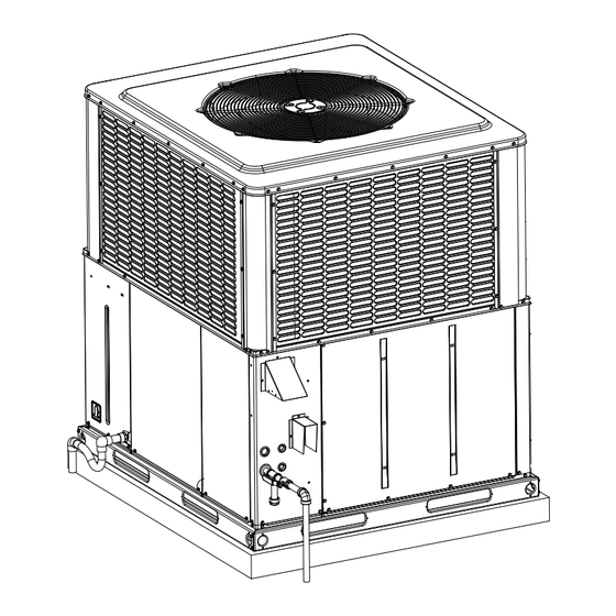
Page 3: Component Location
GAS VALVE COMPRESSOR GAS HEAT EXCHANGER REMOVABLE BURNER BASE RAILS ASSEMBLY A0297-001 FIGURE 1: Component Location Table 1: Unit Limitations Unit Limitations Model Unit Voltage Applied Voltage Outdoor DB Temp Max (°F) PCG4A36 PCG4B48 460-3-60 PCG4B60 Johnson Controls Unitary Products... -
Page 4: Center Of Gravity Location
Table 2: Weights and Dimensions -Three-phase models Model Weight (lbs.) Center of Gravity 4 Point Load Location (lbs.) Shipping Operating 36050 36075 36100 48065 48100 48125 60065 60100 60125 Johnson Controls Unitary Products... -
Page 5: Unit Dimensions
3. Units must be installed outdoors. Over hanging structure or shrubs should not obstruct condenser air discharge outlet. 4. Units may be installed on combustible floors made from class A, B or C roof covering materials only if factory base rails are left in place as shipped. Johnson Controls Unitary Products... -
Page 6: Bottom Duct Dimensions (Inches)
Filters should be checked monthly; this is especially important since this unit is used for both heating and cooling. Model 48, 60 13.6 FIGURE 5: Rear Duct Dimensions (inches) Johnson Controls Unitary Products... -
Page 7: Typical Field Control Wiring Diagram For Gas Heat - Ac Models
3.15 11.8 60065, 60100, 60125 52.0 12.1 0.87 3.15 13.8 1. Minimum Circuit Ampacity. 2. Maximum Over Current Protection per standard UL 1995. 3. Fuse or HACR circuit breaker size installed at factory or field installed. Johnson Controls Unitary Products... -
Page 8: Physical Data
Field-supplied external filters must be sized so as not to exceed 300 FPM air velocity through disposable Quantity - Size filters. All three phase models are shipped with an internal filter rack kit. Consult the instructions supplied with that kit for replacement filter sizes. Filter sizes: A=20x20, B=20x30. Johnson Controls Unitary Products... -
Page 9: Natural Gas Pipe Sizing Chart
The BTU content of the gas may differ with locality. The value should be jurisdiction, wrought iron or steel pipe must be installed at the gas checked with the local gas utility. valve and extend a minimum of two (2) inches outside of the unit cas- ing. Johnson Controls Unitary Products... -
Page 10: Flue Vent Outlet Air Hood
Further communications and action must be given to the home or building owner(s) to eliminate any unauthorized human contact around this area during the heating cycle. Flue hood surfaces and the immediate area reach high temperatures during the heating cycle. Johnson Controls Unitary Products... -
Page 11: Natural Gas Application Data
2. Heating capacity valid for elevations up to 2,000 feet above sea level. For elevations above 2,000 feet, rated capacity should be reduced by 4% for each 1,000 feet above sea level. 3. Based on 2500 BTU/Ft. 4. The air flow must be adequate to obtain a temperature rise within the range shown. Continuous return air temperature should not be below 55°F. Johnson Controls Unitary Products... -
Page 12: Airflow Performance
2. Applications above 0.8" w.c. external static pressure are not recommended. 3. Brushless DC high efficiency standard ECM blower motor used for all indoor blower assemblies. 4. Heating applications tested at 0.50" w.c. esp, and cooling applications tested at 0.30" w.c.esp per standards. Johnson Controls Unitary Products... -
Page 13: Airflow Performance - Bottom Duct Application
2. Applications above 0.8" w.c. external static pressure are not recommended. 3. Brushless DC high efficiency standard ECM blower motor used for all indoor blower assemblies. 4. Heating applications tested at 0.50" w.c. esp, and cooling applications tested at 0.30" w.c.esp per standards. Johnson Controls Unitary Products... -
Page 14: Operation
60 seconds in an attempt to close the pressure switch. This utes or power interruption. Cooling operations are available during a cycle continues indefinitely until either the pressure switch is proved heating lockout. closed, or the call for heat ends. Johnson Controls Unitary Products... -
Page 15: Ignition Control Board Flash Codes
If a call for HEAT occurs (W), the circulating fan switches to W-Speed furnace operation. after a 30 second delay. When the thermostat ends the call for FAN, the thermostat terminal G is de-energized, de-energizing the circulating fan. Johnson Controls Unitary Products... -
Page 16: Gas Valve
Change the incoming line connection phasing to obtain the proper rota- All units have direct drive, multi speed standard ECM blower motors. tion. Connect manometer per “EXTERNAL STATIC PRESSURE SECTION”. Place unit in cooling mode and adjust blower speed accordingly per Table 11 or 12. Johnson Controls Unitary Products... -
Page 17: Measuring External Static Pressure
95 cubic feet of gas per hour are consumed by the furnace at that rate. Multiply 95 x 1050 (the BTU rating of the gas obtained from the local gas company). The result is 99,750 BTUH, which is close to the 100,000 BTUH rating of the unit. Johnson Controls Unitary Products... -
Page 18: Typical Wiring Diagrams
24V phasing 10 Red Flashes Gas valve shorted "ON" 7. BLOWER MOTOR SPEED CONNECTIONS SHOWN ARE TYPICAL, 11 Red Flashes Check blower motor/wiring BUT MAY VARY BY MODEL AND APPLICATION. 5155330-UWD-B-0116 FIGURE 11: Connection Wiring Diagram Johnson Controls Unitary Products... -
Page 19: Ladder Wiring Diagram
VERIFY PROPER OPERATION AFTER SERVICING. 7. BLOWER MOTOR SPEED CONNECTIONS SHOWN ARE TYPICAL, 3. FACTORY WIRED FOR 460 VOLT THREE PHASE SUPPLY POWER. BUT MAY VARY BY MODEL AND APPLICATION. 5155330-UWD-B-0116 FIGURE 12: Ladder Wiring Diagram Johnson Controls Unitary Products... -
Page 20: R-410A Quick Reference Guide
Never open system to atmosphere when under a vacuum. If system must be opened for service, evacuate system then break the vacuum with dry nitrogen and replace all filter driers. FIGURE 13: R-410A Quick Reference Guide Johnson Controls Unitary Products... -
Page 21: Start Up Sheet
Outside air dry bulb temperature Return static (inches of water column) Return air dry bulb temperature Return air wet bulb temperature Total external static pressure Temperature drop Supply air wet bulb temperature Page 1 of 2 Johnson Controls Unitary Products... -
Page 22: Gas Heat
Refrigerant Charge and Metering Device R-410A R-22 Discharge pressure Suction line temperature Data plate - lbs / Oz Fixed Orifice Suction pressure Liquid line temperature Discharge line temperature TXV# / Orifice size Superheat Subcooling Gas Heat Single Stage Two Stage Natural Gas Propane LP (Requires LP Conversion Kit) LP Gas Conversion Kit #...
Need help?
Do you have a question about the PCG4 series and is the answer not in the manual?
Questions and answers