Table of Contents
Advertisement
Quick Links
Advertisement
Table of Contents

Related Manuals for BBK DV113S


Summary of Contents for BBK DV113S
- Page 1 SERVICE MANUAL DV113S...
-
Page 2: Table Of Contents
CONTENTS SAFETY PRECAUTIONS PREVENTION OF ELECTRO STATIC DISCHARGE(ESD)TO ELECTROSTATICALLY SENSITIVE(ES)DEVICES CONTROL BUTTON LOCATIONS AND EXPLANATIONS PREVERTION OF STATIC ELECTRICITY DISCHARGE ASSEMBLING AND DISASSEMBLING THE MECHANISM UNIT OPTICAL PICKUP UNIT EXPLOSED VIEW AND PART LIST BRACKET EXPLOSED VIEW AND PART LIST MISCELLANEOUS ELECTRICAL CONFIRMATION VIDEO OUTPUT (LUMINANCE SIGNAL) CONFIRMATION... -
Page 3: Safety Precautions
1. SAFETY PREAUTIONS 1.1 GENERAL GUIDELINES 1. When servicing, observe the original lead dress. if a short circuit is found, replace all parts which have been overheated or damaged by the short circuit. 2. After servicing, see to it that all the protective devices such as insulation barrier, insulation papers shields are properly installed. -
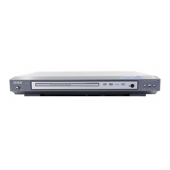
Page 4: Control Button Locations And Explanations
3.Control Button Locations and Explanations Front Panel Illustration POWER switch OPEN/CLOSE button MIC jack Disc tray MIC VOLUME button PLAY/ PAUSE button IR SENSOR button STOP button... -
Page 5: Prevention Of Static Electricity Discharge
4.PREVENTION OF STATIC ELECTRICITY DISCHARGE The laser diode in the traverse unit (optical pickup)may brake down due to static electricity of clothes or human body. Use due caution to electrostatic breakdown when servicing and handling the laser diode. 4.1.Grounding for electrostatic breakdown prevention Some devices such as the DVD player use the optical pickup(laser diode)and the optical pickup will be damaged by static electricity in the working environment.Proceed servicing works under the working environment where grounding works is completed. -
Page 6: Assembling And Disassembling The Mechanism Unit
5. Assembling and disassembling the mechanism unit 5.1 Optical pickup Unit Explosed View and Part List Pic (1) - Page 7 Materials to Pic (1) PARTS CODE PARTS NAME Q ty 14692200 SF-HD60 1EA0311A06300 ASSY, CHASSIS, COMPLETE 1EA0M10A15500 ASSY, MOTOR, SLED 1EA0M10A15501 ASSY, MOTOR, SLED 1EA2451A24700 HOLDER, SHAFT 1EA2511A29100 GEAR, RACK 1EA2511A29200 GEAR, DRIVE 1EA2511A29300 GEAR, MIDDLE, A 1EA2511A29400 GEAR, MIDDLE, B 1EA2744A03000 SHAFT, SLIDE 1EA2744A03100...
-
Page 8: Bracket Explosed View And Part List
5.2 Bracket Explosed View and Part List Pic (2) Materials to Pic(2) 1.bracket 14. front silicon rubber 2.belt 15. Back silicon rubber 3.screw 16. Pick-up 4.belt wheel 17. Pick-up 5.gearwheel 18. switch 6.iron chip 19. Five-pin flat plug 7. Immobility mechanism equipment 20. -
Page 9: Miscellaneous
5.3 MISCELLANEOUS 5.3.1 Protection of the LD(Laser diode) Short the parts of LD circuit pattern by soldering. 5.3.2 Cautions on assembly and adjustment Make sure that the workbenches,jigs,tips,tips of soldering irons and measuring instruments are grounded,and that personnel wear wrist straps for ground. Open the LD short lands quickly with a soldering iron after a circuit is connected. -
Page 10: Electrical Confirmation
6.Electrical Confirmation 6.1. Video Output (Luminance Signal) Confirmation DO this confirmation after replacing a P.C.B. Measurement point Mode Disc Color bar 75% DVDT-S15 Video output terminal PLAY(Title 46):DVDT-S15 PLAY(Title 12):DVDT-S01 DVDT-S01 Measuring equipment,tools Confirmation value 200mV/dir,10 sec/dir 1000mVp-p±30mV Purpose:To maintain video signal output compatibility. 1.Connect the oscilloscope to the video output terminal and terminate at 75 ohms. -
Page 11: Video Output(Chrominance Signal) Confirmation
6.2 Video Output(Chrominance Signal) Confirmation Do the confirmation after replacing P.C.B. Measurement point Mode Disc Color bar 75% DVDT-S15 Video output terminal PLAY(Title 46):DVDT-S15 PLAY(Title 12):DVDT-S01 DVDT-S01 Measuring equipment,tools Confirmation value Screwdriver,Oscilloscope 200mV/dir,10 sec/dir 621mVp-p±30mV Purpose:To maintain video signal output compatibility. 1.Connect the oscilloscope to the video output terminal and terminate at 75 ohme. -
Page 12: Mpeg Board Check Waveform
7.MPEG BOARD CHECK WAVEFORM 7.1 27MHz WAVEFORM DIAGRAM 7.2 ICVIPER22 PIN.5 WAVEFORM DIAGRAM... -
Page 13: Ic Block Diagram & Description
8.2 MT1389 MT1389 Progressive-Scan DVD Player SOC Specifications are subject to change without notice MediaTek MT1389 is a DVD player system-on-chip (SOC) which incorporates advanced features like high quality TV encoder and state-of-art de-interlace processing. The MT1389 enables consumer electronics manufacturers to build high quality, cost-effective DVD players, portable DVD players or any other home entertainment audio/video devices. - Page 14 MT1389 PRELIMINARY, SUBJECT TO CHANGE WITHOUT NOTICE MTK CONFIDENTIAL, NO DISCLOSURE General Feature List 1024-bytes on-chip RAM Super Integration DVD player single chip Up to 4M bytes FLASH-programming interface High performance analog RF amplifier Supports 5/3.3-Volt. FLASH interface Servo controller and data channel processing Supports power-down mode MPEG-1/MPEG-2/JPEG video Supports additional serial port...
- Page 15 MT1389 PRELIMINARY, SUBJECT TO CHANGE WITHOUT NOTICE MTK CONFIDENTIAL, NO DISCLOSURE Audio Effect Processing TV Encoder Dolby Digital (AC-3)/EX decoding Six 108MHz/12bit DACs DTS/DTS-ES decoding Support NTSC, PAL-BDGHINM, PAL-60 MLP decoding for DVD-Audio Support 525p, 625p progressive TV format MPEG-1 layer 1/layer 2 audio decoding Automatically turn off unconnected channels MPEG-2 layer1/layer2 2-channel audio Support PC monitor (VGA)
-
Page 16: U214 Hy29F800
8.3 U214 HY29F800 KEY FEATURES n 5 Volt Read, Program, and Erase n Sector Protection – Minimizes system-level power requirements – Any combination of sectors may be n High Performance locked to prevent program or erase – Access times as fast as 55 ns operations within those sectors n Low Power Consumption n Temporary Sector Unprotect... -
Page 17: Block Diagram
BLOCK DIAGRAM DQ[15:0] A[18:0], A-1 STATE C O N T R O L ERASE VOLTAGE I/O BUFFERS G E N E R A T O R A N D DQ[15:0] S E C T O R S W I T C H E S C O M M A N D W E # REGISTER... - Page 18 PIN CONFIGURATIONS RY/BY# RESET# W E # BYTE# DQ15/A-1 DQ14 DQ13 DQ12 W E # Standard BYTE# RESET# DQ11 TSOP48 DQ15/A-1 RY/BY# DQ10 DQ14 DQ13 DQ10 DQ12 DQ11 BYTE# DQ15/A-1 DQ14 DQ13 DQ12 W E # Reverse RESET# DQ11 TSOP48 RY/BY# DQ10...
-
Page 19: U203 Sdram-Hy57V1610D
8.4 U203 SDRAM-HY57V1610D D E S C R I P T I O N T H E H y n i x H Y 5 7 V 1 6 1 6 1 0 D i s a 1 6 , 7 7 7 , 2 1 6 - b i t s C M O S S y n c h r o n o u s D R A M , i d e a l l y s u i t e d f o r t h e M o b i l e a p p l i c a t i o n s w h i c h r e q u i r e l o w p o w e r c o n s u m p t i o n a n d i n d u s t r i a l t e m p e r a t u r e r a n g e . - Page 20 P I N C O N F I G U R A T I O N V D D V S S D Q 0 D Q 1 5 D Q 1 D Q 1 4 V S S Q V S S Q D Q 2 D Q 1 3...
-
Page 21: Schematic & Pcb Wiring Diagram
9. SCHEMATIC & PCB WIRING DIAGRAM FRONT SCHEMATIC DIAGRAM... - Page 22 FRONT SCHEMATIC DIAGRAM...
- Page 23 POWER SCHEMATIC DIAGRAM...
- Page 24 POWER BOARD SCHEMATIC DIAGRAM...
- Page 25 OK BOARD SCHEMATIC DIAGRAM...
- Page 26 OK BOARD SCHEMATIC DIAGRAMDIAGRAM...
- Page 27 OUTPUT BOARD SCHEMATIC...
- Page 28 OUTPUT BOARD SCHEMATIC...
- Page 29 MIAN SCHEMATIC DIAGRAM...
-
Page 34: Spare Parts List
DV113S MATERIAL LIST 1. POWER BOARD MATERIAL CODE MATERIAL NAME SPECIFICATIONS UNIT QUANTITY LOCATION CARBON FILM RESISTOR 1/4W10K±5% SHAPED 10 R507 0010064 METAL FILM RESISTOR 1/4W10K±1% SHAPED 10 R509 0000461 CARBON FILM RESISTOR 1/4W9.1K±5% SHAPED 10 R512 0010256 METAL FILM RESISTOR 1/4W3.6K±1% SHAPED 10... - Page 35 2100010 CONNECTION CORDS Φ0.6 SHAPED 5mm JP401 6P170 2.0 2PLUG WITH L 2121370 FLAT CABLE XS401 NEEDLE REVERSE 1563482 4911S-1 3. AV BOARD MATERIAL CODE MATERIAL NAME SPECIFICATIONS UNIT QUANTITY LOCATION CARBON FILM RESISTOR 1/4W220Ω±5% SHAPED 10 R701 0000123 CARBON FILM RESISTOR 1/6W330Ω±5% SHAPED 7.5 R709 0090005 SMD RESISTOR...
- Page 36 0310197 SMD CAPACITOR 50V 561 ±10% 0603 C610,C612 0390095 SMD MAGNETIC BEADS FCM1608K-221T05 L601,L603 0880124 NJM4558D DIP U601,U602 6P200 2.0 2PLUG WITH L 2121509 FLAT CABLE XS601 NEEDLE REVERSE 2100010 CONNECTION CORDS Φ0.6 SHAPED 5mm JP603,JP605 JP601,JP602,JP604,JP606,J 2100003 CONNECTION CORDS Φ0.6 SHAPED 7.5mm P607 1980048...
- Page 37 0310596 SMD CAPACITOR 50V 121±20% 0603 C263~C266 0310048 SMD CAPACITOR 50V 151 ±5% NPO 0603 C304,C306 0310051 SMD CAPACITOR 50V 331 ±5% NPO 0603 C318,C319 0310052 SMD CAPACITOR 50V 391 ±5% NPO 0603 C233 C223,C231,C272,C2112,C2 0310066 SMD CAPACITOR 50V 102 ±10% 0603 115,C2116 0310231 SMD CAPACITOR...
- Page 38 1940024 SOCKET 5P 2.0mm XS302 1940005 SOCKET 6P 2.0mm XS303,XS201,XS304...
Need help?
Do you have a question about the DV113S and is the answer not in the manual?
Questions and answers