Table of Contents
Advertisement
Quick Links
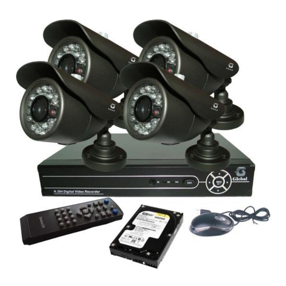
ART. NO. D1004+4XCC3084
H.264 series DVR User's installation and operation
Manual
Edition R1.0
Welcome
Thank you for purchasing our DVR!
This manual is designed to be a reference tool for the installation and operation of your system.
Here you can find information about this series DVR features and functions, as well as a detailed menu
tree.
Before installation and operation please read the following safeguards and warnings carefully!
Important Safeguards and Warnings
Do not place heavy objects on the DVR.
Do not let any solid or liquid fall into or infiltrate the DVR.
Please brush printed circuit boards, connectors, fans, machine box and so on regularly. Before
the dust cleaning please switch off the power supply and unplug it.
Do not disassemble or repair the DVR by yourself. Do not replace the components by yourself.
Page 1
Advertisement
Table of Contents

Related Manuals for GLOBAL Export Import H.264 series

Summary of Contents for GLOBAL Export Import H.264 series
- Page 1 ART. NO. D1004+4XCC3084 H.264 series DVR User’s installation and operation Manual Edition R1.0 Welcome Thank you for purchasing our DVR! This manual is designed to be a reference tool for the installation and operation of your system. Here you can find information about this series DVR features and functions, as well as a detailed menu tree.
- Page 2 Model D1004 Main Processor High performance embedded microprocessor HI3515 Operating System Embedded LINUX System System Resources Pentaplex function: live, recording,playback,backup & remote access User Interface GUI,on-screen menu tips Display Video Standards PAL 625 line,50 f/s;NTSC 525 line,60 f/s Video Compression H.264 main profile Video Recording D1:PAL 1f/s-25f/s NTSC 1f/s-30f/s...
-
Page 3: Table Of Contents
Environment Please place and use the DVR between 0℃ and 40℃.Avoid direct sunlight. Stay away from heat source. Do not install the DVR in damp environment. Do not use the DVR in smoky or dusty environment. Avoid collision or strong fall. Please insure the DVR level installation in a stable workplace. - Page 4 4.2 Record ............................31 4.2.1 Record Config ........................31 4.2.2 Snapshot Storage......................32 4.2.3 Playback ..........................33 4.2.4 Backup ..........................33 4.3 Alarm ............................31 4.3.1 Motion Detect ........................31 4.3.2 Video Blind ........................34 4.3.3 Video Loss ......................... 35 4.3.4 Alarm input ........................35 4.3.5 Alarm output ........................
-
Page 5: Open-Package Check And Cable Connections
2 Open-package check and cable connections 2.1 Open-package check When you receive the DVR, please check first . First, please check whether there is any visible damage to the package appearance. The protective materials used for the package of the DVR can protect most accidental clashes during transportation. Then, please open the box and get rid off the plastic protective materials. -
Page 6: Front Panel
④ fix the screw of hard disk ⑤ connect the data wire ⑥ connect the power wire ⑦ cover the machine ⑧ fix the cover 2.3 Front panel (1) Power indicator light (2) Shift indicator light (3) System status (4)Alarm indicator light (5) Record indicator light (6) Outside operation indicator light (7) Network indicator light (8) HDD indicator light... -
Page 7: Audio And Video Input And Output Connections
2.5 Audio and video input and output connections 2.5.1 Video input connections The video input port is BNC connector plug. The demand of input signal is PAL/NTSC ,75Ω). BNC(1.0V The video signal must be accorded with the state standard which has the high signal to noise ratio, low aberration and low interference. -
Page 8: Audio Signal Input
power supply and the interference introduced by the nearby equipments strictly. The creepage of low quality TV can lead to the damage of other equipments. 2.5.3 Audio signal input Audio port is BNC connection. The input impedance is high so the tone arm must be active. The audio signal line should be firm and away from the electro magnetic Interference and connected credible which avoid false and joint welding and oxidation. - Page 9 3、PTZ decoder connections A. The grounding of the PTZ decoder and DVR must be shared otherwise the common-mode voltage will lead to the PTZ control failure. The shielded twisted pair is recommended. B. Avoid the entrance of high voltage. Make the layout reasonably. Take precaution from the thunder.
-
Page 10: Alarm Input Port Specification
2.6.1 Alarm input port specification 1 channels alarm input. Alarm input type unlimited. The grounding and the com port of the alarm sensor are parallel (The alarm sensor is external power supply) . The grounding of the alarm and the DVR should be shared. The NC port of the alarm sensor must be connected with the DVR alarm input port. -
Page 11: Speed Dome Connections
2.7 Speed dome connections 1、Connect the 485 lines of the speed dome with the DVR 485 interface. 2、Connect the video line with the DVR video input. 3、Electrify the speed dome. Page 11... -
Page 12: Basic Operation
3 Basic operation Note: The button in gray display indicates nonsupport. 3.1 Turn on Plug the power supply and turn on the power supply switch. Power supply indicator light shining indicates turning on the video recorder. After the startup you will hear a beep. The default setting of video output is multiple-window output mode. -
Page 13: System Login
3.3 System Login When the DVR boots up, the user must login and the system provides the corresponding functions with the user purview. There are three user settings. The names are admin, guest and default and these names have no password. Admin is the super user purview; guest and default’s permissions are preview and video playback. -
Page 14: Desktop Shortcut Menu
3.5 Desktop shortcut menu In preview mode you can right click mouse to get a desktop shortcut menu. The menu includes: main menu,record mode,playback,PTZ control,High Speed PTZ,Alarm Output,color Setting,Output adjust,Logout,view1/4/8/9/16 screens. Picture 3.2 Shortcut Menu 3.5.1 Main menu When you login, the system main menu is shown as below. Picture3.3 Main Menu Page 14... -
Page 15: Playback
3.5.2 Playback There are two methods for you to play the video files in the hard disk. 1、 In the desktop shortcut menu. 2、 Main menu>Record->Playback Note: The hard disk that saves the video files must be set as read-write or read-only state.(4.5.1) Picture 3.4 video playback 1. - Page 16 Picture 3.5 detect the storage Detect: Detect the storage connected with the DVR such as hard disk or universal disk. Erasure: Choose the file to delete and click erasure to delete the file. Stop: Stop the backup. Backup: Click backup button and the dialog box is popped up. You can choose the backup file according to the type, channel and time.
- Page 17 【File searching】Search the file according to the searching parameter. Picture 3.7 file searching File type: Set the searching file type. Channel: Set the searching channel. Start Time: Set the searching time scan. 【Playback control】Refer to the following sheet for more information. Button Function Button...
-
Page 18: Record Mode
3.5.3 Record Mode Please check current channel status: “○” means it is not in recording status, “●” means it is in recording status. You can use desktop shortcut menu or click [main menu]> [recording function]> [recording set] to enter the recording control interface. Picture 3.8 Record Mode 【Schedule】Record according to the configuration. -
Page 19: Ptz Control
state. 【Stop】 Click the stop button and the according channel stops alarming no matter the channel in any state. 3.5.5 PTZ control Operation interface is as followed. The functions include: PTZ direction control, step, zoom, focus, iris, setup operation, patrol between spots, trail patrol, boundary scan, assistant switch, light switch, level rotation and so on. - Page 20 Special functions: 1、Preset Set a location for the preset, calls the preset points, PTZ automatically turns to the setting position 1)Preset option Set a location for the preset, procedure is as follows: Step1: in Picture 3.10, click the Direction button will turn into preset position , click the Settings button to enter Picture 3.11.
- Page 21 Value input blank Picture 3.12 PTZ Control 2、Cruise between Points Multiple preset points connected cruise lines, call cruise between points, the PTZ run around on the line 1)Cruise Between Points Settings Cruise lines is connected by multiple preset points, setting procedure is as follows: Step1: In Picture 3.10, the Direction key will turn PTZ to designated location , click Settings button to enter Picture 3.13, Step 2: click Cruise buttons, the write proper value into the Cruise Line and Preset Points blank,...
- Page 22 Preset Points Blank Cruise Button Cruise Line Blank Picture 3.13 Cruise Between Points Settings 2)The Calls of Cruise between Points In Picture 3.10, click Page Shift button, enter PTZ control menu as shown in Picture 3.12. Please input the number of cruise in the value blank, then click Cruise between Points button, PTZ begins to work on the cruise line.
- Page 23 2)Scan Calls In Picture 3.10, click Page Shift button, then enter PTZ control menu as shown in Picture 3.12. Please input the number of scan in the value blank , then click Scan button,PTZ begins to work on the scan line . Click Stop button to stop. 4、Boundary Scan 1)Boundary Scan setup Step1:In Picture 3.10, click Direction button to turn the PTZ to preset direction, then click Setup...
-
Page 24: Color Setting
PTZ restart, all the data clears to 0.。 8、Page Shift In Picture 3.12, click Page Shift button into Picture3.16, setting auxiliary function. Auxiliary number auxiliary switch on the decoder. corresponding to Picture 3.16 Auxiliary Function Control 【Intuitive Auxiliary Operation】 choose auxiliary equipment, select Open or Close button, switch control;... -
Page 25: Output Adjust
3.5.7 Output Adjust Adjust TV output area parameters. You can use the desktop shortcut menu or enter [main menu]> [management tools]> [Output adjust]. Picture 3.19 Output Adjust 3.5.8 Logout Logout, shut down the system or reboot up. You can use the desktop shortcut menu or enter [main menu]. -
Page 26: Main Menu
4 Main menu 4.1 Main menu navigation Main menu Sub menu Function Config Set the recording configuration, recording type, recording time section Record playback Set recording look-up, recording play, video file storage backup Detect or format backup equipment, back the selective files Motion Set motion detect alarm channel, sensitivity, area, linkage parameters: detection... -
Page 27: Record
Serial port Configuration Set serial port function, baud rate, date bit, stop bit, check (RS232) Tour Set patrol mode and interval time Hard disk Set appointed hard disk as read-write disc, read-only disc or redundant management disc, clear data, resume date and so on User Modify user, team or password. - Page 28 recording in the first startup. You can enter [main menu]> [recording function]> [recording setup] to set. Note:There is at least one read-write hard disk.(refer to chapter 4.5.1) Picture 4.1 Record Config 【Channel】Choose the corresponding channel number to set the channel. Choose the all option to set the entire channels.
-
Page 29: Snapshot Storage
Detect:Trigger the “motion detect”, “camera mask” or “video loss” signal. When above alarm is set as opening recording, the “detection recording” state is on. The video file type is “M”. Alarm:Trigger the external alarm signal in the set time section. When above alarm is set as opening recording, the “detection recording”... -
Page 30: Playback
snapshot at related channels. 【Period】Set normal record period,it only startup Snapshot Storage at set period. 【Type】Three types:regular,detect and alarm 【Record type】Three types:regular,detect and alarm Regular: snapshot at set period Detect:snapshot at set period when motion detect,video blind and video loss which are preset for snapshot enable. -
Page 31: Alarm
【Backup】Click backup button and the dialog box is popped up. You can choose the backup file according to the type, channel and time. Picture 4.4 File Backup Remove:Clear the file information. Add:Show the file information satisfying the set file attributes. Start/pause:Click the play button to start the backup and click the pause button to stop the backup. - Page 32 Picture 4.4 Motion Detect 【Channel】Choose the set motion detect channel. 【Enable】■ means that the motion detect function is on. 【Sensitivity】Choose in the six options according to the sensitivity. 【Region】Click setup and enter the set area. The area is divided into PAL22X18. Green block means the current cursor area.
- Page 33 Picture 4.6 set the time section 【Interval】Only one alarm signal is turned on even there are several motion detect signals in the set interval. 【Alarm output】 Start the external equipment of corresponding linkage alarm when the motion detect alarm is turned on. 【Delay】Delay a few moments and stop when the alarm state is turned off.
-
Page 34: Video Blind
Picture 4.8 PTZ Activation 【Delay】When alarm is over,recording will last some seconds(10~300sec),then stop. 【Show message】Pop the alarm information dialog box in the local host computer screen. 【Send EMAIL】■ means sending an email to user when the alarm is turned on. Note:Set in the [NetService] and send email. -
Page 35: Video Loss
4.3.3 Video Loss When the equipment can not obtain the channel video signal, the video loss alarm is turned on and the linkage function is turned on. Picture 4.10 Video loss Set method: refer to chapter 4.3.1. Motion detect Note:"Advanced" button is the same as rightclick. 4.3.4 Alarm input When the equipment obtains the external alarm signal, the alarm function is turned on. -
Page 36: Alarm Output
Set method: refer to chapter 4.3.1. Motion detect Note:"Advanced" button is the same as rightclick. 4.3.5 Alarm output Refer to chapter 3.5.4. 4.3.6 Abnormal Analysing and inspecting current software and hardware of the device: When some abnormal events happen,the device will make a relative answer such as show message and buzzer. Picture 4.12 Abnormal 【Event Type】... -
Page 37: General
4.4.1 General Picture 4.13 General setup 【System time】Set the system data and time. 【Date format】Choose the data format: YMD, MDY, DMY. 【Date Separator】Choose list separator of the data format. 【Time Format】Choose time format: 24-hour or 12-hour. 【Language】English,French,Portugueses,Russian,Italian,S-Chinese, T-Chinese,Spanish,Thai,Greek,Japanese,German,Polish. 【HDD full】Choose stop record: Stop recording when the hard disk is full. Choose overwrite: Cover the earliest recording files and continue recording when the hard disk is full. -
Page 38: Encode
Picture 4.14 DST (week) Picture 4.15 DST (date) 4.4.2 Encode setup Set the video/audio code parameter: video file, remote monitoring and so on. Set every independent channel’s coding parameter in the left part, and set the combine encode parameter in the right part. Note: Combine encode introduces video compression technique which combines and compresses multi-channel’s video to a special channel.Applying for multi-channel playback simultaneously, Dial-up multi-channel real-time monitor, mobile monitor and so on. -
Page 39: Network
【Channel】Choose the channel number. 【Compression】Standard H.264 main profile. 【Resolution】Resolution type:D1/ HD1/CIF / QCIF. 【Frame Rate】P:1 frame/s~25 frame/s; N: 1 frame/s~30 frame/s 【Bit Rate Type】You can choose limited code stream or variable code stream. When you choose the variable code stream there are six image quality options. 【Bit Rate】Set the code stream value to modify the image quality. -
Page 40: Netsevice
【Net Card】You can choose cable network card or wireless network card. 【DHCP Enable】Obtain IP address automatically(not suggested) Note:DHCP server is preinstalled. 【IP address】Set the IP address. Default: 192.168.1.10. 【Subnet mask】Set the subnet mask code. Default: 255.255.255.0. 【Gateway】Set the default gateway. Default: 192.168.1.1. 【DNS setup】Domain Name Server. - Page 41 【PPPoE setup】 Picture4.19 PPPOE Input the user name and password that ISP(Internet service provider)provides. After saving it reboot up your system. Then the DVR will build a network connection based on PPPoE. The IP address will change into dynamic IP address after above operation is well done. Operation:...
- Page 42 Update Period:The same with the NTP server check interval. Default: 10minutes. 【EMAIL setup】 If the alarm is turned on or the alarm linkage photos are taken, send an email about the alarm information and the photos to appointed address. Picture 4.21 EMAIL SMTP server:Email server address.
- Page 43 are supportive in the list. You can delete the set IP address by √ in the options. Note: When the same IP address is in the white and black list at the same time, the black list precedence is higher. Picture 4.22 IP IP FILTER 【DDNS】...
- Page 44 【FTP setup】FTP is available only when alarm happens,or alarm activates record and snapshot,it will upload related record and snapshot pictures to FTP server. Picture 4.24 FTP setup 【Enable】Click Enable,then all settings will be available 【Server IP】 IP address for FTP server 【Port】...
- Page 45 Picture 4.25 Wireless Config 【Enable】Choose Enable to make all settings available 【Type】Dial type,default AUTO 【Wireless AP】3G access point 【Dial Number】3G Dial Number 【User Name】User name of 3G 【Password】Password of dial user 【IP Address】IP address,got from dial 【Mobile Monitor Setup】 To visit the device by mobile,pls make a router mapping of this port and use CMS to monitor and operate it by protocol.
-
Page 46: Gui Display
【UPNP】UPNP protocol can auto port forwarding on router,make sure UPNP is running on router before use it. Picture 4.27 【Enable】Choose Enable to make sure all UPNP settings available 【HTTP】Route will automatically distribute HTTP port for the device,when IE viewing,it need this port(eg. - Page 47 Picture 4.28 GUI Display 【Channel Title】Click the channel name modify button and enter the channel name menu. Modify the channel name. The 16 Chinese characters and 25 letters are supportive. 【Time Display】means the selective state. Display the system data and time in the surveillance window.
-
Page 48: Ptz
4.4.6 PTZ setup Picture 4.29 PTZ setup 【Channel】Choose the dome camera input channel. 【Protocol】Choose the corresponding dome protocol. (PELCOD as an example) 【Address】Set as the corresponding dome address. Default: 1.(Note:The address must be consistent with the dome address.) 【Baudrate】 Choose the corresponding dome baud rate length. You can control the PTZ and vidicion. Default: 115200. -
Page 49: Rs232
4.4.7 RS232 setup Picture 4.30 RS232 setup 【Serial Port Function】Common serial port is used to debug and update program or set up specific serial port. 【Baud rate】Choose the corresponding baud rate length. 【Data bits】Include 5-8 options. 【Stop bits】Include 2 options. 【Parity】Include odd, even, mark, space. -
Page 50: Advanced
Picture 4.31 tour setup 【interval】Set the patrol switch interval. The set range is 5-120 seconds. Note: means turn off/on the patrol. 4.5 Advanced 4.5.1 HDD Manage Configure and manage the hard disk. The menu displays current hard disk information: hard disk number, input port, type, status and overall capability. -
Page 51: Account
Picture4.32 HDD Manage 4.5.2 Account Manage the user purview. Note:1. The character length is 8 bytes at most for the following user and user team name. The blank ahead or behind the character string is invalid.The middle blank in the character string is valid. Legal characters include: letter, number, underline, subtraction sign, dot. - Page 52 Picture 4.33 Account 【Modify User】Modify the existed user attribute. 【Modify Group】Modify the existed team attribute. 【Modify Password】Modify the user password. You can set 1-6 bit password. The blank ahead or behind the char string is invalid. The middle blank in the char string is valid. Note:The user who possess the user control purview can modify his/her own or other users password Picture 4.34 Modify Password...
- Page 53 We recommend that the common user’s purview is lower than the advanced user. Picture 4.35 add user 【Add Group】Add a user team and set the purview. There are 36 different purviews: shut down the equipment, real time surveillance, playback, recording setup, video file backup and so on. Picture 4.36 Add Group 【Delete User】Delete the current user.
-
Page 54: Online User
Picture 4.37 Delete Group 4.5.3 Online User Look up the network user information in the local DVR. You can choose the network user and cut the connection. Then the user is locked until next boot-strap. Picture 4.38 Online User 4.5.4 TV adjust Refer to chapter 3.5.7 . -
Page 55: Auto Maintain
4.5.5 Auto Maintain The user can set the auto reboot time and auto file deleting time limit. Picture 4.39 Auto maintain 4.5.6 Restore The system restore to the default setup. You can choose the items according to the menu. Picture 4.40 Restore Page 55... -
Page 56: Upgrade
4.5.7 Upgrade Upgrade Picture 4.41 【 Upgrade】choose USB interface. 【Upgrade file】choose the file which needs upgraded. 4.5.8 Device Info Provide device interface info like audio in,alarm in/out to be conveniently used for user. Picture 4.42 Device Info. 4.6 Info 4.6.1 HDD info Display the hard disk state: hard disk type, overall capability, residual capability, the recording time and so on. -
Page 57: Bps
Picture 4.43 HDD Info Clue:○ means that the hard disk is normal. X means that the hard disk is broken-down.- means that there is no hard disk. If the user need to change the damaged hard disk, you must shut down the DVR and take up all the damaged hard disks,then install a new one. -
Page 58: Log
Picture 4.44 BPS 4.6.3 LOG Look up system log according to the set mode. Log information include: system operation, configuration operation, data management, alarm affair, recording operation, user management, file management and so on. Set the time section to look up and click the look up button. -
Page 59: Version
4.6.4 Version Display the basic information such as hardware information, software edition, issue data and so on. Picture 4.46 Version 4.7 Shut down system Refer to chapter 3.5.8. Page 59... -
Page 60: Faq And Maintenance
5 FAQ and maintenance 5.1 FAQ If the problems are not listed, please contact the local service or call the HQ service. We are willing to offer the service. 1、 The DVR can not boot up normally. Possible reasons are as followed: The power supply is not correct. - Page 61 Possible reasons are as followed: The program is not matched. Please update the program. The image brightness is all 0. Please restore the default setup. There is no video input signal or the signal is too weak. The channel protection or the screen protection is set. The hardware of the DVR is damaged.
- Page 62 It is not an active tone arm. It is not an active sound box. The audio lines are damaged. The hardware of the DVR is damaged. 9、 There is audio signal in the surveillance window but mo audio signal in the playback state.
- Page 63 The sensitivity is too low. Limited by some hardware edition. 13、 I can not login via web or CMS. Possible reasons are as followed: The system is windows 98 or win me. We recommend updating to windows 2000sp4 or higher Version or installing the software for low edition. ActiveX is hold back.
- Page 64 The data is too much. Please stop recording and backup. The data exceeds the backup storage. The backup equipment is not compatible. The backup equipment is damaged. 17、 The keyboard can not control the DVR. Possible reasons are as followed: The serial port of the DVR is not set correctly.
-
Page 65: Maintenance
Possible reasons are as followed: Front vidicon quality is bad. The lens is too dirty. The vidicon is in backlighting installation. The hard disk capability is not enough. The hard disk is damaged. 22、 The downloading files can not play. Possible reasons are as followed: There is no media player. -
Page 66: Appendix 1.Remote Controller Operation
Appendix 1.Remote controller operation (6) (1) (5) (7) (4) (3) (2) Serial Name Function number Multi-window Same function as Multi-window button in the front button panel Numeric button Code input/number input/channel switch 【Esc】 Same function as【Esc】button in the front panel Direction button Same function as direction button in the front panel Record control... -
Page 67: Appendix 2.Mouse Operation
Appendix 2.Mouse operation *Take right hand as an example The mouse in USB connection is supported. Operation Function Double click one item in the file list to playback the video Double click the playback video to zoom in or out the Double left click screen Double click the channel to make it full screen display... -
Page 68: Appendix 3.Hard Disk Capability Calculation
Appendix 3.Hard disk capability calculation Make sure the hard disk installed to the DVR for the first time. Pay attention to the IDE hard disk lines connection. 1、 Hard disk capability There is no limit for recording machine. We recommend 120G~250G size to keep better stability. - Page 69 INSTRUCTION MANUAL IR Waterproof Color Camera MODEL: CC3084 To prevent fire or shock hazard do not expose the insides of the unit WARNING to rain or moisture. This symbol alerts the user to the presence of important operating and maintenance issues according to the manual.
- Page 70 SPECIFICATIONS Image Sensor COLOR 1/3" CMOS PC 1089 NTSC:728(H)×488(V) PAL:728(H)×488(V) Effective Pixels 600TVL Horizontal Resolution Sync System Internal Scanning system Interlace 2:1 Electronic Shutter NTSC: 1/60s~1/100000s PAL:1/50s~1/100000s White Balance Auto Gamma 0.45 ≥48dB S/N Ratio 1.0Vp-p 75Ω, BNC connection Video Output Usable Illumination 0Lux/F2.0 (When IR LEDs on) Waterproof level...
- Page 71 CONNECTION One monitor system with two or more cameras: CAMERA AC ADAPTER VIDEO MONITOR PRECAUTIONS (a)Do not attempt to disassemble the camera. To prevent electric shock, do not remove screws or covers. There are no user serviceable parts inside. Ask a qualified service person for servicing.
- Page 72 FEATURES Introduces advanced CMOS and digital technology, with IR-Cut Function and offers customers a high quality and high resolution picture. Compared with the old chipset, the sensitivity, smear, dynamic range and S/N are improved drastically. 24pcs IR Black LEDs can improve the night vision. ...
Need help?
Do you have a question about the H.264 series and is the answer not in the manual?
Questions and answers