
Related Manuals for Panasonic AG-BS300E


Summary of Contents for Panasonic AG-BS300E
-
Page 1: Operating Instructions
Operating Instructions Base Station Before operating this product, please read the instructions carefully and save this manual for future use. ENGLISH F0909T0 -F @ VQT2H41 Printed in Japan... -
Page 2: Read This First
AC plug. Please safety, if you are in any doubt about the effective contact either a local or foreign Panasonic grounding of the power outlet, please consult a authorized service center for assistance in qualified electrician. -
Page 3: Important Safety Instructions
Read this first ! (continued) For AG-BS300P IMPORTANT SAFETY INSTRUCTIONS 1) Read these instructions. 2) Keep these instructions. 3) Heed all warnings. 4) Follow all instructions. 5) Do not use this apparatus near water. 6) Clean only with dry cloth. 7) Do not block any ventilation openings. - Page 4 Read this first ! (continued) For AG-BS300E Caution for AC Mains Lead FOR YOUR SAFETY PLEASE READ THE FOLLOWING TEXT CAREFULLY. This product is equipped with 2 types of AC mains cable. One is for continental Europe, etc. and the other one is only for U.K.
- Page 5 Read this first ! (continued) For AG-BS300E WARNING: CAUTION: THIS EQUIPMENT MUST BE EARTHED. In order to maintain adequate ventilation, do not To ensure safe operation, the three-pin plug must install or place this unit in a bookcase, built-in be inserted only into a standard three-pin power cabinet or any other confined space.
- Page 6 Read this first ! (continued) EMC NOTICE FOR THE PURCHASER/USER OF THE APPARATUS 1. Applicable standards and operating environment (AG-BS300E) The apparatus is compliant with: standards EN55103-1 and EN55103-2 1996.11, and electromagnetic environments E1, E2, E3, and E4. 2. Pre-requisite conditions to achieving compliance with the above standards <1>...
-
Page 7: Table Of Contents
Part Names and Functions........13 Front Panel..............13 Rear Panel ..............14 Supplied Accessories AC cable (AG-BS300P) a 1 AC cables (AG-BS300E) a 2 Rack Mount Adapters a 2 Rack Mount Adapter Screws a 6 Features This unit has the following features: The unit is connected to the camera adapter (AG-CA300G;... -
Page 8: System Configuration Diagram
System Configuration Diagram RET OUT Monitor SDI OUT VIDEO OUT VF/return video (Composite signal) VF OUT BS IN Intercom tally Dedicated cable BT-LH80W/WU (monitor video, GPI) CA IN Return (SDI) Use 5C-FW REMOTE Return (Maximum (Composite signal) Remote cable extension length: SD I IN... -
Page 9: Precautions When Connecting The System
Precautions When Connecting the System Take caution with the following when connecting the camera adapter and this unit. To connect the camera adapter and the unit, use a power INCOM becomes disconnected temporarily when the supply cable of the specification described in [About the video format is changed on the camera recorder. -
Page 10: Camera Extension System And Camera Recorder Configuration Example
Camera Extension System and Camera Recorder Configuration Example Connection with the AG-HPX300/301/302/304 AG-CA300G AG-BS300P/E RET signal selection switch switch BT-LH80W/WU VF OUT BS IN Separation (signal A) RET SDI SDI IN Multiplex SDI OUT2 SDI OUT1 SDI IN (signal B) VIDEO GENLOCK GENLOCK... -
Page 11: Connection With Camera Recorders Other Than Ag-Hpx300/301/302/304 Or Ag-Hpx500/502
Camera Extension System and Camera Recorder Configuration Example (continued) Connection with camera recorders other than AG-HPX300/301/302/304 or AG-HPX500/502 AG-CA300G AG-BS300P/E RET signal selection switch switch BT-LH80W/WU VF OUT BS IN Separation (signal A) RET SDI VF cable * Multiplex SDI1 SDI IN (signal B) VIDEO... -
Page 12: Connection With The Ag-Hpx500/502
Camera Extension System and Camera Recorder Configuration Example (continued) Connection with the AG-HPX500/502 Viewfinder or BT-LH80W/WU AG-CA300G AG-BS300P/E RET signal CA VF selection switch switch AG-YA500G VF OUT BS IN LENS Separation (signal A) RET SDI CAM VF LENS Multiplex SDI1 SDI IN (signal B) -
Page 13: Part Names And Functions
Part Names and Functions Front Panel PUSH OPERATE INCOM INCOM TALLY/CALL MENU LEVEL POWER Base Station AG-BS300 POWER switch TALLY lamp/CALL switch This is the main power switch when using an AC power This is turned on while the TALLY signal is input to this supply. -
Page 14: Rear Panel
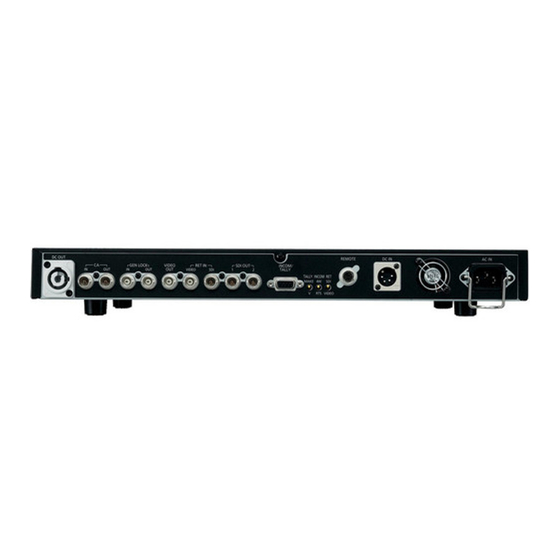
Part Names and Functions (continued) Rear Panel DC OUT 24V REMOTE DC IN 12V AC IN GEN LOCK VIDEO OUT RET IN SDI OUT LOOP OUT (MENU) VIDEO INCOM/TALLY INCOM TALLY MAKE 4W VIDEO 14 15 DC OUT 24 V connector RET IN SDI signal connector DC 24 V is output while this unit is operating with the AC This is an input connector for the return video signal... - Page 15 Part Names and Functions (continued) 14. RET signal selection switch 18. Cable hook This is a switch to select the return signal from this unit This is used to prevent the AC power supply cable to the camera adapter. slipping off. Select the RET signal supplied to either the 7.RET IN VIDEO signal connector or the 8.RET IN SDI signal connector.
-
Page 16: About The Signals To Input To Genlock In Connector
About the Signals to Input to GENLOCK IN Connector Supply the following signals to the GENLOCK IN connector, as a GENLOCK input signal to this unit, in accordance with the video format used. Video may be disrupted if any other signals are supplied. Video format of the camera recorder Signal to be supplied to the GENLOCK IN connector (analog signal) When HD SYNC is supplied... -
Page 17: About The Rack Mount
About the Rack Mount This unit can be installed onto an EIA standard rack. Using the 6 included rack mount adapter screws, mount the included rack mount adapters. Loosen the screws, and remove the 4 pedestals. Mount onto the rack using screws (commercially available). -
Page 18: About The Power Supply Cable
About the Power Supply Cable Use the power supply cable with the following specifications with the unit. The extension length of 100 m cannot be maintained between this unit and the camera adapter especially if the resistance value is larger than the following specifications. (CE01-6A18-11PC-D0;... -
Page 19: Menu Display
Menu Display Setting menu can be displayed in the video output from the VIDEO OUT (MENU) connector in the rear panel of this unit. Basic structure of the menu Menu setting is operated with the MENU switch and the SEL GENLOCK GL PHASE :HD SDI... -
Page 20: List Of Menus
List of Menus <SYSTEM> Item / Data Saved Variable Range Note FORMAT 1080-59.94i Displays the format used in this unit. 1080-23.98PsF Status display only. 1080-24PsF This cannot be changed by the menu. 1080-50i 720-59.94P 720-50P 720-60P 480-59.94i 576-50i CAMERA VF HD/LCD Set the format of the viewfinder used on the camera recorder. - Page 21 List of Menus (continued) <DOWNCON SETTING> Only displayed when in HD mode Item / Data Saved Variable Range Note DOWNCON SQUEEZE Set the mode for the composite signal output from the VIDEO OUT (MENU) MODE SIDE-CROP connector. LETTER BOX SQUEEZE: Video will be squeezed horizontally.
-
Page 22: Connector Signals
Connector Signals Panasonic part number Panasonic part number INCOM DC OUT 24 V K1AB105H0003 K1AY105J0004 INCOM MIC GND Standby Manufacturer part number Manufacturer part number HA16PRH-5S CE01-2A18-11SC-D0 INCOM MIC (Hirose Denki) (DDK Ltd.) INCOM RECEIVE GND 24 V Cable side connector... -
Page 23: Specifications
Specifications [General] [Digital Signal Input Unit] RET IN SDI: Input: AC 100 V - 240 V, 50/60 Hz, 1.6 A - 0.6 A BNC, 75 h DC 12 V, 1.1 A For HD SDI, compliant to SMPTE292M/299M Standard Output: DC 24 V, 4 A 1080/59.94i, 1080/23.98PsF, 1080/24PsF, 1080/50i, 720/59.94P, 720/50P For SD SDI, compliant to SMPTE259M-C/272M-A... - Page 24 Panasonic Broadcast & Television Systems Company Unit Company of Panasonic Corporation of North America Executive Office: One Panasonic Way 4E-7, Secaucus, NJ 07094 Tel: 201-348-7000 Eastern Zone: One Panasonic Way 4E-7, Secaucus, NJ 07094 Tel: 201-348-7196 Southeast Region: Tel: 201-392-6151 Western Zone: 3330 Cahuenga Blvd W., Los Angeles, CA 90068 Tel: 323-436-3608...
Need help?
Do you have a question about the AG-BS300E and is the answer not in the manual?
Questions and answers