Table of Contents
Advertisement
Quick Links
Advertisement
Table of Contents

Subscribe to Our Youtube Channel
Related Manuals for Icom IC-M302


Summary of Contents for Icom IC-M302
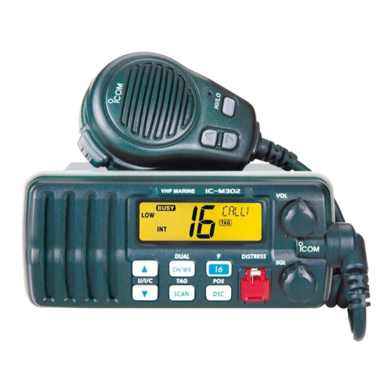
- Page 1 SERVICE MANUAL VHF MARINE TRANSCEIVER M302...
- Page 2 This service manual describes the latest service information NEVER connect the transceiver to an AC outlet or to a DC for the IC-M302 VHF MARINE TRANSCEIVER at the time of power supply that uses more than 16 V. Such a connection publication.
-
Page 3: Table Of Contents
TABLE OF CONTENTS SECTION SPECIFICATIONS SECTION INSIDE VIEWS SECTION DISASSEMBLY INSTRUCTIONS SECTION CIRCUIT DESCRIPITON RECEIVER CIRCUITS ........... . . 4-1 TRANSMITER CIRCUITS . - Page 4 SECTION 1 SPECIFICATIONS ‘ ‘ GENERAL • Frequency coverage : 156.025–157.425 MHz (Tx) 156.050–163.275 MHz (Rx) • Mode : 16K0G3E (FM) 16K0G2B (DSC) • Usable channels : All USA, international and Canadian channels plus 10 weather channels • Power supply requirement : 13.8 V DC ±10 % (negative ground) •...
- Page 5 ‘ ‘ VHF MARINE CHANNEL LIST Channel No. Frequency (MHz) Channel No. Frequency (MHz) Channel No. Frequency (MHz) Transmit Receive Transmit Receive Transmit Receive 156.050 160.650 157.050 157.050 156.525 156.525 156.050 156.050 Rx only 161.650 156.575 156.575 156.100 160.700 157.100 161.700 156.625 156.625...
-
Page 6: Section 2 Inside Views
SECTION 2 INSIDE VIEWS • MAIN UNIT AF power amplifier (IC6: LA4425A) YGR amplifier (Q18: 2SC4226 R25) Antenna switch (D1, D2: XB15A308) +5V regulator (IC9: TA7805S) Pre-driver Reference oscillator (Q17: 2SC4215 O) (X2: CR-768) DSC decoder (IC3: NJM2211M) VCO circuit Analog switch (IC7: TC4W66F) Ceramic bandpass filter... -
Page 7: Section 3 Disassembly Instructions
SECTION 3 DISASSEMBLY INSTRUCTIONS • • REMOVING THE MAIN UNIT REMOVING THE CASE 1 Unscrew 8 screws, A, as shown below, and then remove 1 Unsolder the external speaker cable, F (2 points), and the case in the direction of the arrow. DC cable, G (2 points), on the bottom side. -
Page 8: Receiver Circuits
SECTION 4 CIRCUIT DESCRIPTION 4-1 RECEIVER CIRCUITS nals at the 1st mixer circuit (Q2) to produce a 21.7 MHz 1st IF signal. 4-1-1 ANTENNA SWITCHING CIRCUIT (MAIN UNIT) The 1st IF signal is applied to two crystal filters (FI1, FI2) to The antenna switching circuit functions as a low-pass filter suppress out-of-band signals and is then amplified at the IF while receiving and as resonator circuit while transmitting. -
Page 9: Transmitter Circuits
When the weather alert function is activated and a 1050 Hz alert tone from an NOAA weather radio broadcast is received, the IC-M302 emits beep tones and indicates flash- 4-2-4 POWER AMPLIFIER CIRCUIT (MAIN UNIT) ing “ALT” on the display to inform of an emergency weather The power amplifier circuit amplifies the driver signal to an report on the air. -
Page 10: Pll Circuits
4-2-5 APC CIRCUIT (MAIN UNIT) The PLL circuit , using a one chip PLL IC (MAIN unit; IC8), directly generates the transmit frequency and receive 1st IF The APC circuit stabilizes transmit output power. frequency with VCOs. The PLL sets the divided ratio based on serial data from the CPU on the LOGIC BOARD and The RF output signal from the power amplifier (IC4) is compares the phases of VCO signals with the reference... -
Page 11: Dsc Circuits
4 steps LCD backlight (DS2–DS7). • UART PORT IC-M302 has the UART port which is used for cloning data and NMEA interface. The signals pass through the photo coupler circuit (IC2), and are then applied to the buffer amplifier (IC3, pin 2). -
Page 12: Port Allocations
4-7 PORT ALLOCATIONS 4-7-1 CPU (LOGIC BOARD; IC1) Port Port Description Description number name number name Input port for the HM-141 key signals. Input port for the [Distress] switch. DTRS Low: While the [Distress] switch is Pushed key Input voltage pushed. -
Page 13: Section 5 Adjustment Procedures
SECTION 5 ADJUSTMENT PROCEDURES 5-1 PREPARATION ‘ ‘ REQUIRED TEST EQUIPMENT EQUIPMENT GRADE AND RANGE EQUIPMENT GRADE AND RANGE Output voltage : 13.8 V DC Frequency range : 300–3000 Hz DC power supply Audio generator Current capacity : 10 A or more Measuring range : 1–500 mV Measuring range... -
Page 14: Pll Adjustments
5-2 PLL ADJUSTMENTS ADJUSTMENT MEASUREMENT POINT ADJUSTMENT ADJUSTMENT CONDITION VALUE UNIT LOCATION UNIT ADJUST LOCK • Operating channel : ch16 MAIN Connect a digital 1.8 V Verify VOLTAGE • Receiving multi-meter or oscil- loscope check point LV. • Operating channel : ch16 1.6 V •... -
Page 15: Transmitter Adjustments
5-3 TRANSMITTER ADJUSTMENTS ADJUSTMENT MEASUREMENT POINT ADJUSTMENT ADJUSTMENT CONDITION VALUE UNIT LOCATION UNIT ADJUST OUTPUT • Operating channel : ch16 Rear Connect 23.5 W MAIN R135 POWER • Output power : High Panel power meter to the • Transmitting antenna connector. FREQUENCY •... -
Page 16: Receiver Adjustments
5-4 RECEIVER ADJUSTMENT ADJUSTMENT MEASUREMENT POINT ADJUSTMENT ADJUSTMENT CONDITION VALUE UNIT LOCATION UNIT ADJUST SENSITIVITY • Operating channel : ch16 MAIN • Connect the dis- Maximum voltage MAIN • [SQUELCH] control: tortion meter to the Max. counterclockwise [EXT SP] jack with a 4 Ω... -
Page 17: Section 6 Parts List
SECTION 6 PARTS LIST 6-1 IC-M302 [LOGIC BOARD] ORDER [VR BOARD] DESCRIPTION ORDER DESCRIPTION 7030003530 S.RESISTOR ERJ3GEYJ 562 V (5.6 kΩ) 7030003560 S.RESISTOR ERJ3GEYJ 103 V (10 kΩ) 7210003140 VARIABLE TP96N97N-15SK-10KA-2685 7030003560 S.RESISTOR ERJ3GEYJ 103 V (10 kΩ) 7030003560 S.RESISTOR ERJ3GEYJ 103 V (10 kΩ) - Page 18 [MAIN UNIT] [MAIN UNIT] ORDER ORDER DESCRIPTION DESCRIPTION 1110003490 S.IC TA31136FN (D,EL) 7030003640 S.RESISTOR ERJ3GEYJ 473 V (47 kΩ) ERJ3GEYJ 561 V (560 Ω) 1110005320 S.IC NJM13403V-TE1 7030003410 S.RESISTOR ERJ3GEYJ 1R0 V (1 Ω) 1110003650 S.IC NJM2211M-TE1 7030004050 S.RESISTOR 1150002170 S-AV35 (I) 7030003680 S.RESISTOR...
- Page 19 [MAIN UNIT] [MAIN UNIT] ORDER ORDER DESCRIPTION DESCRIPTION R133 7030003680 S.RESISTOR ERJ3GEYJ 104 V (100 kΩ) 4030009500 S.CERAMIC C1608 CH 1H 0R5B-T R135 7310002670 S.TRIMMER RV-143 (RH03A3AS2) 471 4030009520 S.CERAMIC C1608 CH 1H 020B-T R136 7030003590 S.RESISTOR ERJ3GEYJ 183 V (18 kΩ) 4030007010 S.CERAMIC C1608 CH 1H 100D-T...
- Page 20 [MAIN UNIT] [MAIN UNIT] ORDER ORDER DESCRIPTION DESCRIPTION C166 4030006860 S.CERAMIC C1608 JB 1H 102K-T 6510021720 S.CONNECTOR 30FLT-SM1-TB C167 4510005310 S.ELECTROLYTIC ECEV1CA220SR 6510023810 CONNECTOR B5B-PH-K-S C171 4010008050 CERAMIC HM60SJ CH 180J 500V C172 4030006860 S.CERAMIC C1608 JB 1H 102K-T C173 4030006860 S.CERAMIC C1608 JB 1H 102K-T...
- Page 21 6-2 HM-141 [MAIN UNIT] ORDER DESCRIPTION 7010007590 RESISTOR RD1/4S 123JTA <FG> 7010007600 RESISTOR RD1/4 682JTA <FG> 7010007610 RESISTOR RD1/4 153JTA <FG> 7010007620 RESISTOR RD1/4 333JTA <FG> 4030018660 S.CERAMIC C1608 JB 1H 223K-T <FG> 4030018670 S.CERAMIC C1608 CH 1H 471J <FG> 7700002640 MICROPHONE KUC3523-040245 <FG>...
- Page 22 SECTION 7 MECHANICAL PARTS AND DISASSEMBLY [CHASSIS PARTS] [LOGIC BOARD] REF. NO. ORDER NO. DESCRIPTION QTY. REF. NO. ORDER NO. DESCRIPTION QTY. 6510004880 Connector MR-DSE-01 5030002590 LCD IS08251E00V0 8900012330 Cable OPC-1258 8930061040 LCD contact SRCN-2685-SP-N-W 8010019300 2685 Chassis 8210019840 2685 Reflector 8930061050 2685 R-Bush plate 8930060510 2685 LCD holder 8510015570 2685 Case...
- Page 23 MP3 ( A ) 137 (5 13 32 MP2 ( A ) MP15 ( C ) MP4 ( C ) MP16 ( C ) MP15 (C) Unit: mm (inch) MP6 ( F ) LOGIC BOARD MP11 ( C ) MP16 (C) 153 (6 1 32 30.7 (1...
-
Page 24: Hm–141
[CHASSIS PARTS] [MAIN UNIT] REF. NO. ORDER NO. DESCRIPTION QTY. REF. NO. ORDER NO. DESCRIPTION QTY. 8900012211 Cable OPC-1249A [Black] 7700002640 Microphone KUC3523-040245 8900012221 Cable OPC-1250A [White] 8900012501 Cable OPC-1285A [Gray] 8210020110 2715 front panel [Black] 8210020130 2715 front panel (A) [White] 8210020370 2715 front panel (B) [Gray]... -
Page 25: Section 8 Semi-Conductor Information
SECTION 8 SEMI-CONDUCTOR INFORMATION • TRANSISTOR AND FET’S 2SA1577 Q 2SB1132 R 2SC4116 BL 2SC4215 O 2SC4226 R25 (Symbol: HP) (Symbol: BARB) (Symbol: LL) (Symbol: QO) (Symbol: R25) 3SK131 L DTA144EU DTC114EU DTC114 TU DTC144EU (Symbol: V12) (Symbol: 16) (Symbol: 14) (Symbol: 04) (Symbol: 26) FMW1... -
Page 26: Section 9 Board Layouts
SECTION 9 BOARD LAYOUTS 9-1 MAIN UNIT • TOP VIEW B—6015C C206 R204 C246 R165 R151 C205 R203 C243 C255 C306 R168 C111 R211 C224 R173 C241 C124 R212 C135 R183 C128 R181 C126 R213 C127 R182 C106 C125 C130 R210 C304 C138... - Page 27 to the power supply • BOTTOM VIEW Red cable Black cable VCC2 VCC1 Gray cable SP— to the external speaker HV GND Blue cable 9 - 2...
-
Page 28: Logic Unit
9-2 LOGIC UNIT • TOP VIEW B—6096A SP— to the MAIN unit J1 9 - 3... - Page 29 • BOTTOM VIEW 9 - 4...
-
Page 30: Vr Board
9-3 VR BOARD • TOP VIEW to the MAIN unit W1 VOL1 VOL2 • BOTTOM VIEW 9 - 5... -
Page 31: Sql Board
9-4 SQL BOARD • TOP VIEW to the MAIN unit W1 SQLI SQLV • BOTTOM VIEW 9 - 6... - Page 32 9-5 HM-141 • TOP VIEW 9 - 7...
- Page 33 • BOTTOM VIEW 9 - 8...
-
Page 34: Block Diagram
SECTION 10 BLOCK DIAGRAM MAIN UNIT FRONT UNIT EXT SP HM–141 IC2A: NJM13403V WXDEC IC3: IC6: NJM2211M LA4425A SP1: FI3: ALFY450E 045P0803 INT SP DSCDEC DECODER CERAMIC VR BOARD IC1: TA31136FN D1,D2: IC7B: FI1,FI2: XB15A308 TC4W66F 2SC4116 BL FL–363 2SC4215 O 3SK131 L 3SK131 L TP96N97N–15SK–10KA–2685... -
Page 35: Voltage Diagram
SECTION 11 VOLTAGE DIAGRAM 11-1 GENERAL LOGIC BOARD 045P0803 SP– FRONT UNIT B4B–2R–SM3–TF NMEA+ HM-141 NMEA– ICF3 SQL BOARD VR BOARD OPC-1263 (FRONT unit; W3) MAIN UNIT 11 - 1... -
Page 36: Main Unit
11-2 MAIN UNIT 68 k NJM13403V 10 k 10 k LS–440 10 k R: 2.30V R: 7.25V R: 3.22V WXDEC LS–440 LS–440 0.5 P 100 P 10 P CDB450C24 0.01 LS–440 10 P IC3 NJM2211M 3SK131 L 0.033 3SK131 L 0.047 TA31136FN 15 k... -
Page 37: Logic Unit
11-3 LOGIC UNIT 4.20V 2.80V 1.40V DIM MAX: 12.4V IS08251E00V0 2SB1132 R SP– 2SC4116 BL 2SC4116 BL 30FLT–SM1–TB SP– SP– BEEP BEEP 39 k BPLVL BPLVL SQLV SQLV DSCENC DSCENC WXDEC WXDEC SEG14 RMUTE RMUTE P67/AN7 SEG13 PC357N6T KEYM SEG13 DSCDEC DSCDEC P66/AN6... -
Page 38: Vr / Sql Boards
11-4 VR/SQL BOARD VR BOARD TP96N97N–15SK–10KA–2685 J1 S5B–ZR VOL2 VOL1 SQL BOARD J1 S3B–ZR SQLV SQLI 11 - 4... -
Page 39: Hm–141
11-5 HM–141 KUC3523–040245 SKHHLPA010 CHASSIS UNIT W1 MICG SKHHLPA010 6.8 k KEYM SKHHLPA010 15 k DOWN UP ON 2.0V DN ON 3.0V 16/9 ON 3.8V SKHHLPA010 33 k 11 - 5... - Page 41 S-14011IZ-C1 1-1-32, Kamiminami, Hirano-ku, Osaka, 547-0003, Japan © 2003 Icom Inc.
Need help?
Do you have a question about the IC-M302 and is the answer not in the manual?
Questions and answers