Table of Contents
Advertisement
INSTALLATION, OPERATING AND
SERVICE INSTRUCTIONS FOR
As an ENERGY STAR
PVG-7 meet the ENERGY STAR
Protection Agency (EPA).
For service or repairs to boiler, call your heating contractor. When seeking information on boiler, provide
Boiler Model Number and Serial Number as shown on Rating Label.
Model Number
Heating Contractor
Address
103997-06 - 1/14
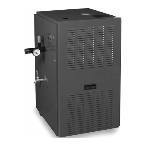
PVG™
Gas - Fired Boiler
Partner, U.S. Boiler Company has determined that the PVG-3, PVG-4, PVG-5, PVG-6 and
®
guidelines for energy efficiency established by the United States Environmental
®
Boiler Serial Number
9700609
Installation Date
Phone Number
Price - $5.00
Advertisement
Table of Contents

Subscribe to Our Youtube Channel
Related Manuals for U.S. Boiler Company PVG3


Summary of Contents for U.S. Boiler Company PVG3
- Page 1 PVG™ Gas - Fired Boiler 9700609 As an ENERGY STAR Partner, U.S. Boiler Company has determined that the PVG-3, PVG-4, PVG-5, PVG-6 and ® PVG-7 meet the ENERGY STAR guidelines for energy efficiency established by the United States Environmental ®...
- Page 2 IMPORTANT INFORMATION - READ CAREFULLY NOTE: The equipment shall be installed in accordance with those installation regulations enforced in the area where the installation is to be made. These regulations shall be carefully followed in all cases. Authorities having jurisdiction shall be consulted before installations are made.
- Page 3 Special Installation Requirements for Massachusetts A. For all side wall horizontally vented gas fueled equipment installed in every dwelling, building or structure used in whole or in part for residential purposes and where the side wall exhaust vent termination is less than seven (7) feet above grade, the following requirements shall be satisfied: 1.
- Page 4 WARNING This boiler requires regular maintenance and service to operate safely. Follow the instructions contained in this manual. Improper installation, adjustment, alteration, service or maintenance can cause property damage, personal injury or loss of life. Read and understand the entire manual before attempting installation, start-up operation, or service.
-
Page 5: Table Of Contents
TABLE OF CONTENTS I. Pre-Installation ....... 7 VIII. System Start-up ......35 II. Unpack Boiler ........ 8 IX. Operation ........39 III. Venting ........... 9 X. Troubleshooting ......43 IV. Water Piping and Trim ....19 XI. Service .......... 48 V. -
Page 7: Pre-Installation
I. PRE-INSTALLATION Protect gas ignition system components from water WARNING (dripping, spraying, rain, etc.) during boiler operation and service (circulator replacement, condensate trap, If you do not follow these instructions exactly, control replacement, etc.). a fire or explosion may result causing property damage or personal injury. -
Page 8: Unpack Boiler
I. PRE-INSTALLATION (continued) 6. For boiler located within unconfined space in confined space. Use indoor air if two permanent building of unusually tight construction or within openings communicate directly with additional confined space, provide outdoor air through two space(s) of sufficient volume such that combined permanent openings which communicate directly or volume of all spaces meet criteria for unconfined by duct with the outdoors or spaces (crawl or attic) -
Page 9: Venting
(snorkel through a side wall) Table 2: Vent System Components Included with Boiler Gasketed Vent System Components Part Number Vent Terminal 3” - Horizontal PVG3 thru PVG6) 8110701 Vent Terminal 3” - Horizontal (PVG7) 8116310 Vent Terminal 4” - Horizontal (PVG8 & PVG9) - Page 10 Max. Min. Max. 6. After it has been determined that each appliance PVG3 & PVG4 remain ing connected to the common venting system properly vents when tested as outlined above, return PVG5 & PVG6 doors, win dows, exhaust fans, fireplace dampers and...
- Page 11 III. VENTING (continued) Au moment du retrait d’une chaudière existante, General Guidelines les mesures suivantes doivent être prises pour 1. Vent system installation must be in accordance chaque appareil toujours raccordé au système with National Fuel Gas Code, ANSI Z223.1/NFPA d’evacuation commun et qui fonctionne alors que 54, Natural Gas and Propane Installation Code, d’autres appareils toujours raccordés au système...
- Page 12 III. VENTING (continued) Maximum support spacing is five (5) feet (1.5 m). g. Minimum 10 feet (2 m) horizontally from an Do not penetrate any part of the vent system with operable opening in an adjacent building. This fasteners. does not apply to vent terminals 2 feet (0.6 m) or more above or 25 feet (7.6 m) or more below Soutenez parties horizontales de ventilation pour operable openings.
- Page 13 III. VENTING (continued) 2. Do not exceed maximum vent lengths. Refer to Install Vent Pipe, U.S. Boiler Gasketed Vent System. Table 4. 1. Procedure for Joining U.S. Boiler Gasketed Vent 3. Recommended horizontal installation consists Pipe and Fittings. See Figure 3. of vent being sloped down ¼...
- Page 15 III. VENTING (continued) Figure 5: Horizontal – Vent Terminal Configuration (3” or 4” Vent) NOTICE Roof penetrations require the use of roof flashing and storm collar - not supplied with boiler. 3. Slope horizontal runs minimum ¼ inch per foot. Slope towards vertical vent drain tee.
- Page 18 III. VENTING (continued) Optional Exterior Separate Horizontal Vent Terminal Mounting – See Figure 9. 3. Install vent piping. 1. See Figure 28 for Blower Vent Connector Assembly. a. Install vent piping for desired venting system. Do not exceed maximum vent lengths. Refer to Refer to specific section for details for vent pipe Table 4.
-
Page 19: Water Piping And Trim
IV. WATER PIPING AND TRIM WARNING Failure to properly pipe boiler may result in improper operation and damage to boiler or structure. Oxygen contamination of boiler water will cause corrosion of iron and steel boiler components, and can lead to boiler failure. U.S. Boiler’s Standard Warranty does not cover problems caused by oxygen contamination of boiler water or scale (lime) build-up caused by frequent addition of water. - Page 20 IV. WATER PIPING AND TRIM (continued) 5. When constructing a piping tree to install LWCO 2. The recommended location for an Auxiliary Limit select fittings (tees, elbows etc) and nipples to have on gas hot water boilers is in the supply piping. See the same size (NPT) as boiler supply connection.
- Page 21 IV. WATER PIPING AND TRIM (continued) NOTICE U.S. Boiler recommends sizing the system circulator to supply sufficient flow (GPM) to allow a 20°F temperature differential in the system. When sizing the system circulator, the pressure drop of all radiators, baseboard and radiant tubing and all connecting piping must be considered.
- Page 22 IV. WATER PIPING AND TRIM (continued) bring the pH between 7 and 11. To perform a long term pressure test including the boiler, ALL trapped air must first be removed from the If it is required to perform a long term pressure boiler.
-
Page 25: Gas Piping
Gas Pressure (in. w.c.) (in. w.c.) Pressure Pressure (in. w.c.) Inlet to Gas Valve Inlet to Gas Valve (in. w.c.) (in. w.c.) PVG3 PVG4 PVG5 PVG6 11.0 10.0 PVG7 PVG8 PVG9 NOTICE PVG boilers built for altitudes greater than 4,999 feet above sea level do not need to be specially orificed for applications up to 10,000 feet. - Page 26 V. GAS PIPING (continued) Table 7: Maximum Capacity of Schedule 40 Pipe in CFH* For Natural Gas Pressures of 0.5 psig or Less 0.3 inch w.c. Pressure Drop 0.5 inch w.c. Pressure Drop Length [Feet] ½ ¾ 1¼ ½ ¾ 1¼...
- Page 27 V. GAS PIPING (continued) 2. Locate leaks using approved combustible gas Pressure test. The boiler and its gas connection must detector, soap and water, or similar nonflammable be leak tested before placing boiler in operation. solution. 1. Protect boiler gas control valve. For all testing over ½...
-
Page 28: Electrical
VI. ELECTRICAL DANGER Positively assure all electrical connections are unpowered before attempting installation or service of electrical components or connections of the boiler or building. Lock out all electrical boxes with padlock once power is turned off. WARNING Failure to properly wire electrical connections to the boiler may result in serious physical harm. Electrical power may be from more than one source. - Page 29 VI. ELECTRICAL (continued) Figure 17: Wiring Connection Diagram...
- Page 30 VI. ELECTRICAL (continued) NOTICE All wire, wire nuts, controls etc. are installer supplied unless otherwise noted. If an additional system limit is used, install in series with the auxiliary limit jumper shown in the drawing below. Figure 18: Wiring Ladder Diagram...
-
Page 33: Modular Installation
VII. MODULAR INSTALLATION General Guidelines Gas Piping 1. Read and follow all venting, combustion air, 1. Refer to National Fuel Gas Code, Local Codes and water piping, gas piping and electrical instructions Tables 7 and 8 for gas pipe sizing. contained in this manual unless otherwise instructed Table 9: Modular Boiler Water Manifold Sizing in this section. -
Page 35: System Start-Up
VIII. SYSTEM START-UP Verify that the venting, water piping, gas piping and 6. Open fill valve (Make-up water line should be electrical system are installed properly. Refer to located directly after full port ball valve in system installation instructions contained in this manual. supply piping between air scoop and expansion tank). - Page 36 VIII. SYSTEM START-UP (continued) Figure 22: Operating Instructions...
- Page 37 VIII. SYSTEM START-UP (continued) 3. Main burners and pilot burner will extinguish and Check pilot burner flame. See Figure 24. Flame blower will stop when water level drops below low should be steady, medium hard blue enveloping 3/8 to water cutoff probe. Verify limit, thermostat or other ½...
- Page 38 VIII. SYSTEM START-UP (continued) b. Increase input rate if less than 98% of rating WARNING plate input. Increase manifold gas pressure no more than 0.3 inch w.c. If measured input rate is Failure to properly adjust gas input rate will result still less than 98% of rated input: in over firing or under firing of the appliance.
-
Page 39: Operation
IX. OPERATION Table 11: Sequence of Operation Boiler Sequence of Operation Status Codes displayed in STA Mode NORMAL OPERATION Status Description 1. The PVG Boilers are equipped with an Intelligent Hydronic Control (control). This control replaces the Standby traditional separate ignition control, high limit switch, (Burner off No call for heat detected Circulator off) - Page 40 IX. OPERATION (continued) The STA (status) display code has the below listed values. This list is also available on the control cover. Status Code Displayed in STA Mode Standby Waiting for Pressure Switch to Open Waiting for Pressure Switch to Close Prepurge Spark Flame Proving...
- Page 41 IX. OPERATION (continued) panel settings allow water flow to the priority zone CHANGING THE ADJUSTABLE PARAMETERS after the call for heat ends. The Circulator Overrun To adjust parameters such as High Limit Setpoint and Time is adjustable between 0 through 10 minutes. High Limit Differential: 4.
- Page 42 IX. OPERATION (continued) 7. Domestic Hot Water (DHW) Terminal Function (dh_) Table 14: DHW Terminal Function (dh_) Selection = Domestic Hot Water Demand, The control allows configuration of the DHW (Parameter dh_ = dh) Circulator output functionality to help the PVG integrate into each installation more effectively.
-
Page 43: Troubleshooting
X. TROUBLESHOOTING check the wiring on the boiler against the wiring Before troubleshooting diagram in Figures 17 and 18. Ensure that incoming The following pages contain trouble shooting tables for 120 Vac power polarity is correct and that the boiler use in diagnosing control problems. - Page 44 X. TROUBLESHOOTING (continued) Use Control Display ERR (error) Number To Direct TroubleShooting Efforts If the control detects an error it will flash “Err” (error) followed by a number. Use this number to identify the boiler problem and corrective action in the table below. If there is no Err display proceed to next Section: IQ Boiler Control Error Codes (when "Err"...
- Page 45 X. TROUBLESHOOTING (continued) Use STA (status) Number To guide TroubleShooting The control will flash “STA” followed by a number. Use this number to identify the boiler problem in the table below: 1. Boiler and Circulator Off Display / Recommended Corrective Action Status The boiler has not detected a call for heat (tt = off and dh = off).
- Page 46 X. TROUBLESHOOTING (continued) 5. Circulator is On, Blower is On but Boiler Fails to Start Display / Status Description The Boiler is in “Retry Delay”: - The burner failed to light (no flame signal). After a 5 minute delay, control will attempt to light the burner STA 10 again.
- Page 47 X. TROUBLESHOOTING (continued) 6. Circulator is On, Blower is On but Boiler Fails to Start (continued) Display / Status Recommended Corrective Action 1. No Spark a. Can you hear sparking while STA 6 is displayed? - If there is no spark noise replace the control. b.
-
Page 48: Service
XI. SERVICE DANGER This boiler uses flammable gas, high voltage electricity, moving parts, and very hot water under high pressure. Assure that all gas and electric power supplies are off and that the water temperature is cool before attempting any disassembly or service. Do not attempt any service work if gas is present in the air in the vicinity of the boiler. - Page 49 XI. SERVICE (continued) WARNING This boiler must only be serviced and repaired by skilled and experienced service technicians. If any controls are replaced, they must be replaced with identical models. Read, understand and follow all the instructions and warnings contained in all the sections of this manual.
- Page 50 XI. SERVICE (continued) 5. Disconnect Wiring Harness from Blower Motor. 6. Remove Canopy/Blower Assembly. a. Loosen the (4) screws from Canopy. 7. Remove Flue Gas Baffles. Inspect Flue Gas Baffles for deterioration. 8. Inspect flue passages. Clean with flue brush. See Figure 29.
- Page 52 XI. SERVICE (continued) Table 16: Pilot Burner Location Model Main Burner with Pilot Bracket Pilot Burner Located Between Main Burners * PVG3 2 & 3 PVG4 3 & 4 PVG5 4 & 5 PVG6 5 & 6 PVG7 6 & 7 PVG8 7 &...
-
Page 53: Repair Parts
XII. REPAIR PARTS All PVG Repair Parts may be obtained through your local U.S. Boiler Wholesale distributor. Should you require assistance in locating a U.S. Boiler distributor in your area, or have questions regarding the availability of U.S. Boiler products or repair parts, please contact U.S. Boiler Customer Service at (717) 481-8400 or Fax (717) 481-8408. - Page 54 XII. REPAIR PARTS (continued)
- Page 55 XII. REPAIR PARTS (continued) [Quantity] Part Number Description PVG3 PVG4 PVG5 PVG6 PVG7 PVG8 PVG9 1. CASTING ASSEMBLY Section Assembly 61707031 61707041 61707051 61707061 61707071 61707081 61707091 Left End Section 71707001 Center Section 71707003 71707003 71707003 71707003 71707003 71707003 71707003...
- Page 56 XII. REPAIR PARTS (continued)
- Page 57 XII. REPAIR PARTS (continued) [Quantity] Part Number Description PVG3 PVG4 PVG5 PVG6 PVG7 PVG8 PVG9 2. BASE ASSEMBLY Base Wrapper 71807031 71807041 71807051 71807061 71807071 71807081 71807091 Base Tray 71807032 71807042 71807052 71807062 71807072 71807082 71807092 Burner Tray Assembly 61807031 61807041 61807051 61807061 61807071 61807081 61807091...
- Page 58 XII. REPAIR PARTS (continued) [Quantity] Part Number Description PVG3 PVG4 PVG5 PVG6 PVG7 PVG8 PVG9 3. BASE ASSEMBLY Burner Cover (Natural Gas Only) 102033-03 102033-04 102033-05 102033-06 102033-07 102033-08 102033-09 Manifold Support Bracket 718070001 Sheet Metal Screw, #8 x 1/2”...
- Page 59 XII. REPAIR PARTS (continued) [Quantity] Part Number Description PVG3 PVG4 PVG5 PVG6 PVG7 PVG8 PVG9 4. FAN/CANOPY ASSEMBLY Canopy Assembly - Sea Level 61107031 61107041 61107051 61107061 61107071 61107081 61107091 Canopy Assembly - High Altitude 61107032 61107042 61107052 61107062 61107072...
- Page 61 XII. REPAIR PARTS (continued) [Quantity] Part Number Description PVG3 PVG4 PVG5 PVG6 PVG7 PVG8 PVG9 5. BURNER ASSEMBLY Gas Valve (Natural Gas), 81660282 Honeywell VR8204P1171 Gas Valve (Natural Gas), 81660283 Honeywell VR8304P4496 Gas Valve (LP Gas), 81660146 Honeywell VR8204C3015 Gas Valve (LP Gas),...
- Page 62 XII. REPAIR PARTS (continued) [Quantity] Part Number Description PVG3 PVG4 PVG5 PVG6 PVG7 PVG8 PVG9 6. CONTROL PANEL ASSEMBLY Limit Rated Temperature Sensor, 12”, 103195-01 Honeywell 50001464-001 Transformer, Honeywell AT140B1297 102516-01 Boiler Control, Induced Draft, 103661-01 Honeywell S9361A2075 Control Panel...
- Page 63 XII. REPAIR PARTS (continued) [Quantity] Part Number Description PVG3 PVG4 PVG5 PVG6 PVG7 PVG8 PVG9 7. JACkET PARTS Left Side Panel 60407002 Right Side Panel 60407001 Rear Panel 60407033 60407043 60407053 60407063 60407073 60407083 60407093 Vestibule Panel 60407034 60407044 60407054...
- Page 64 XII. REPAIR PARTS (continued) [Quantity] Part Number Description PVG3 PVG4 PVG5 PVG6 PVG7 PVG8 PVG9 8. MISCELLANEOUS PARTS CARTON Water Manifold 80607001 Temperature/Pressure Gauge 100282-01 Circulator Wiring Harness 6130701 Safety Relief Valve 81660363 Boiler Drain Valve 806603061 Vent Terminal 8110701...
-
Page 65: Appendix A - Figures
APPENDIX A - FIGURES Figure Page Description Number Number Figure 1 Minimum Clearances to Combustibles Figure 2 Dimensions Section III - Venting Figure 3 U.S. Boiler Gasketed Vent Joint Detail Figure 4 Horizontal - Vent Installation Figure 5 Horizontal - Vent Terminal Configuration (3” or 4” Vent) Figure 6 Vertical Vent Installation Figure 7... -
Page 66: Appendix B - Tables
APPENDIX B - TABLES Table Page Description Number Number Section III - Venting Table 1 Vent System Options Table 2 Vent System Components Included with Boiler Table 3 Vent System Components Table 4 Vent Length Section V - Gas Piping Table 5 Gas Ratings Table 6... -
Page 67: Service Record
SERVICE RECORD DATE SERVICE PERFORMED... - Page 68 U.S. Boiler Company, Inc. P.O. Box 3020 Lancaster, PA 17604 1-888-432-8887 www.usboiler.net...
Need help?
Do you have a question about the PVG3 and is the answer not in the manual?
Questions and answers