
Related Manuals for AlterG M300 Series


Summary of Contents for AlterG M300 Series
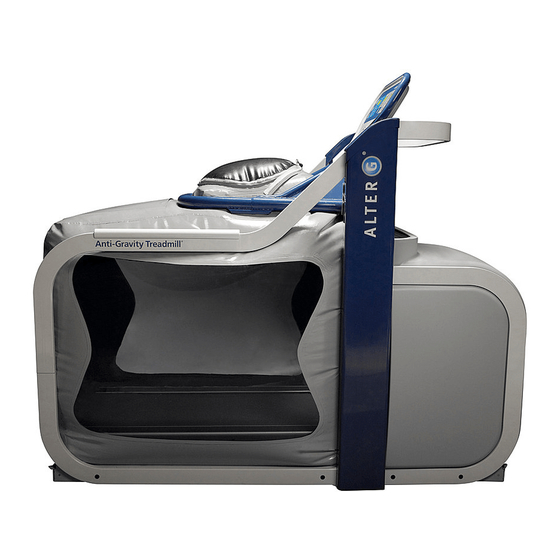
- Page 1 AlterG Anti-Gravity Treadmill® M300 Series Installation Manual AlterG Installation Manual 105440 rev C...
- Page 2 This manual covers installation and service procedures for the following AlterG products for rehabilitation and fitness applications: AlterG Anti-Gravity Treadmill M310 AlterG Anti-Gravity Treadmill M320 NOTE: The following symbol is used throughout this manual to call attention to steps or operational procedures that may directly affect your safety or the safe operation of the AlterG Anti-Gravity Treadmill.
-
Page 3: Table Of Contents
SITE REQUIREMENTS ......................... 8 Treadmill Dimensions ......................8 Electrical Requirements ......................8 INSTALLATION OF THE FULLY ASSEMBLED ALTERG (roll-in) ............9 Moving the AlterG System to a Location ................9 Removing the AlterG from the Pallet ..................9 Removing the AlterG from the Dollies .................. 9 Preparing the System for Operation ................... -
Page 4: Alterg Component Identification
ALTERG COMPONENT IDENTIFICATION These photos identify the major components and nomenclature used in the assembly of the AlterG system. Exterior Components Cockpit Stanchion Caps Front cover Side cover Stanchion AlterG Installation Manual 105440 rev C... -
Page 5: Interior Components
Interior Components Modesty Panel Muffler Valve Blower AlterG Installation Manual 105440 rev C... -
Page 6: General Installation Guidelines
GENERAL INSTALLATION GUIDELINES Safety Many assemblies of the AlterG are heavy. Use good lifting technique and obtain assistance when lifting and moving these components. Use appropriate lifting and moving aids. It is recommended that installers wear steel toed shoes while working around the AlterG. -
Page 7: Fasteners And Torque Specifications
Bottom rail covers Assembly Torque 6 ft-lb / 8 Nm 9 in-lb / 1 Nm 9 in-lb / 1 Nm 6 ft-lb / 8 Nm 9 in-lb / 1 Nm 32 in-lb / 1Nm AlterG Installation Manual 105440 rev C... -
Page 8: Site Requirements
Note: Place the right front corner of the system within 8 feet of the power outlet. Electrical Requirements A dedicated 20 Amp, 220V circuit; with a NEMA 6-20 receptacle required within eight feet of the front right corner of the AlterG Anti-Gravity Treadmill ®. Single Phase NEMA 6-20R Receptable Voltage across A and B: 200-240VAC... -
Page 9: Installation Of The Fully Assembled Alterg (Roll-In)
The Alter System comes strapped to a wooden pallet; because of the weight (≈ 700 lbs) and size of the machine, the only practical way of moving the AlterG while on the pallet is with a forklift. Alternatively, you can remove the AlterG from the pallet for moving as outlined below. -
Page 10: Preparing The System For Operation
2. On each inner stanchion wall there is a ½” bolt as pictured below. Use a ¾” box or socket wrench to loosen and remove the bolt and washer. These bolts and washers can be discarded upon removal. Counterweight bolt AlterG Installation Manual 105440 rev C... - Page 11 8. Check wall voltage. The M310/ M320 will operate between 200 – 240Vac. AlterG Installation Manual 105440 rev C...
-
Page 12: Assembly Instructions For The Disassembled Unit
ASSEMBLY INSTRUCTIONS FOR THE DISASSEMBLED UNIT Moving the AlterG 1. Verify site inspection survey, final location, and route to final location. 2. Use a pallet jack or transport on furniture dollies. A J-bar is useful for lifting the pallet for placement of the dollies. - Page 13 Note: Use good lifting technique when moving the cockpit. 7. Remove the load cell cables from the interior of the treadmill motor cover. Note: be very careful when operating around these cables to avoid damaging them. AlterG Installation Manual 105440 rev C...
- Page 14 The power cord is 10 feet in length. Place the front right corner of the base within 8 feet of the electrical outlet to provide slack for cord routing. Load cell cables exit here AlterG Installation Manual 105440 rev C...
-
Page 15: Base Assembly
Note: The wheels should not ride up on the top of the guides. 5. Remove the blue tape from each corner of the base and pull out the black plastic rods and place aside. AlterG Installation Manual 105440 rev C... -
Page 16: Installing The Stanchion Assembly
Note: Lower it in from the top or bring it in from the rear to avoid damaging the load cell cables. Do not slide it in from the front of the unit. AlterG Installation Manual 105440 rev C... - Page 17 You may have to look through the outer clearance hole of the rail to line up the inner rail hole with the threaded hole in the base. Do not tighten at this time. AlterG Installation Manual 105440 rev C...
-
Page 18: Installation Of The Cockpit
- make sure it does not catch on the modesty panel when the cockpit is lowered. Aluminum pads 4. Once cockpit is inside the stanchion channels, lock it into place. AlterG Installation Manual 105440 rev C... - Page 19 7. Lower the counterweight while maintaining tension in the cable. Align the counterweight so that the tapped hole faces inward. 8. Move the cockpit over its full range from top to bottom checking to make sure it operates smoothly. AlterG Installation Manual 105440 rev C...
-
Page 20: Installation Of The Cable Guide
5. Connect the load cell cables exiting from the cable to powe r box guide to the corresponding cables coming from the base. The load cell cables are labeled. Make sure the connectors lock in place. AlterG Installation Manual 105440 rev C... - Page 21 Treadmill signal cable 9. Connect the treadmill signal cable coming from the treadmill PCB to its corresponding cable coming from the cable guide. AlterG Installation Manual 105440 rev C...
-
Page 22: Diagnostic Mode
The hook extends through the motor pan. A 7/16” wrench is used to tighten or loosen Tighten here the corresponding nut located on underside under the pan. To gain access to the AlterG Installation Manual 105440 rev C... -
Page 23: Check Treadbelt Tracking
2. Increase treadbelt tension by tightening the rear roller adjustment bolts. Tighten each one equally until the belt no longer slips. Do not over-tighten. If you can't reach the palm of your hand under the center of the treadbelt, the belt is too tight. AlterG Installation Manual 105440 rev C... -
Page 24: Bag Installation
These hems are captured in the 4 corresponding tubes. Slide a rod into the hem, and then insert the assembly into the corresponding tube on the cockpit. Replace and tighten the retaining screws. AlterG Installation Manual 105440 rev C... - Page 25 6. Use the specified rubber strip and hose clamp to secure the bag cone around the ABS reducer, just below the quick release pin. AlterG Installation Manual 105440 rev C...
- Page 26 Place a rubber strip around the port and clamp the pressure tube and cables with the specified clamp. Elbow pushed down to cuff AlterG Installation Manual 105440 rev C...
- Page 27 15. Push the rod through, tucking the hem into the groove ahead of the rod. Using Tri- Flow lubricant and twisting the rod while you push will help it slide through. AlterG Installation Manual 105440 rev C...
- Page 28 18. The end of the rod should align with the end of the groove in the base. 19. Insert the remaining side rod followed by the back and front rods following the same procedure. AlterG Installation Manual 105440 rev C...
-
Page 29: Rail Installation
Rail Installation 1. Unwrap all the rails. The AlterG graphic should be facing the outside of the system. The rails bolt to the stanchions and the base. Rails 2. For all handrails, align braces and begin installing screws. The rail to stanchion connections use a 5/16”- 24 socket flathead,... - Page 30 Stanchion to base socket cap screws c. Front rail to base cap screws d. Rail to stanchion socket flathead screws e. Rail to base socket cap screws f. Rail to rail buttonhead socket screws AlterG Installation Manual 105440 rev C...
-
Page 31: Install The Main Power Cable
4. Secure the main power cable to the welded lug located on the inside of the right front rail. Use the padded clamp provided. Place the clamp 10 feet (3 meters) from the plug end of the cable. AlterG Installation Manual 105440 rev C... -
Page 32: Final Installation Steps
Push the bottom of the panel in so that the Velcro squares adhere. 3. Install the stanchion covers. These each use seven 6-32 x 1/4” socket buttonhead screws. AlterG Installation Manual 105440 rev C... - Page 33 5. Insert the plastic plate in the pocket on the top rear of bag. 6. Insert the nickel plated caps in the holes in the rails and on the front and rear of the base. There are 10 caps total. AlterG Installation Manual 105440 rev C...
- Page 34 Congratulations! You’re finished installing the AlterG M300 treadmill. Turn the system on, put on some shorts, and test out the unit for 15 minutes to ensure that everything works properly. AlterG Installation Manual 105440 rev C...
Need help?
Do you have a question about the M300 Series and is the answer not in the manual?
Questions and answers