Table of Contents
Advertisement
Quick Links
Philips Consumer Communications
CUSTOMER SERVICES
Author : Fabrice TANT
Approval : Jean Pierre HOLLANDE
Operational manager
PCC/VY/691/E/XENIUM989/0025/MLD/MLD
SERVICE REPAIR SUPPORT
PROCEDURE
SERVICE MANUAL
Repair for Cellular Telephone
XENIUM DUAL BAND
LEVEL 1
PHILIPS
PCC/VY/691/E/XENIUMDB989LVL1/0025/MLD/MLD
Revision : 2
Date : 19/06/2000
Page 1 out of 24
- 1 -
Advertisement
Table of Contents

Related Manuals for Philips Xenium Dual Band


Summary of Contents for Philips Xenium Dual Band
- Page 1 SERVICE REPAIR SUPPORT Revision : 2 Author : Fabrice TANT PROCEDURE Approval : Jean Pierre HOLLANDE Date : 19/06/2000 Operational manager Page 1 out of 24 SERVICE MANUAL Repair for Cellular Telephone XENIUM DUAL BAND LEVEL 1 - 1 - PCC/VY/691/E/XENIUM989/0025/MLD/MLD...
-
Page 2: Revision
PHILIPS Philips Consumer Communications CUSTOMER SERVICES PCC/VY/691/E/XENIUMDB989LVL1/0025/MLD/MLD SERVICE REPAIR SUPPORT Revision : 2 Author : Fabrice TANT PROCEDURE Approval : Jean Pierre HOLLANDE Date : 19/06/2000 Operational manager Page 2 out of 24 Service Manual Last updates: DATE MODIFICATION PAGE... -
Page 3: Table Of Contents
PHILIPS Philips Consumer Communications CUSTOMER SERVICES PCC/VY/691/E/XENIUMDB989LVL1/0025/MLD/MLD SERVICE REPAIR SUPPORT Revision : 2 Author : Fabrice TANT PROCEDURE Approval : Jean Pierre HOLLANDE Date : 19/06/2000 Operational manager Page 3 out of 24 1.0 PURPOSE--------------------------------------------------------------------------------------------------------------------------------------4 2.0 SCOPE------------------------------------------------------------------------------------------------------------------------------------------4 3.0 REFERENCE----------------------------------------------------------------------------------------------------------------------------------4 4.0 GLOSSARY/ACRONYM LIST-----------------------------------------------------------------------------------------------------------4 5.0 TEST EQUIPMENT AND TOOLS------------------------------------------------------------------------------------------------------4... -
Page 4: Service Repair Support
Hardware Authorized Service Center National Service Center Test SIM Card Used for functionality of PHILIPS Mobiles Test SIM Card “SP” SIM Card that is used to stimulate the user interface and allow radio tests 5.0 TEST EQUIPMENT AND TOOLS Equipment / Tools Production Test SIM Card - Part No. -
Page 5: Test And Inspection Plan
PHILIPS Philips Consumer Communications CUSTOMER SERVICES PCC/VY/691/E/XENIUMDB989LVL1/0025/MLD/MLD SERVICE REPAIR SUPPORT Revision : 2 Author : Fabrice TANT PROCEDURE Approval : Jean Pierre HOLLANDE Date : 19/06/2000 Operational manager Page 5 out of 24 6.0 TEST AND INSPECTION PLAN The test plan is derived from the Product Test Reference for XENIUM DB. -
Page 6: Before Starting
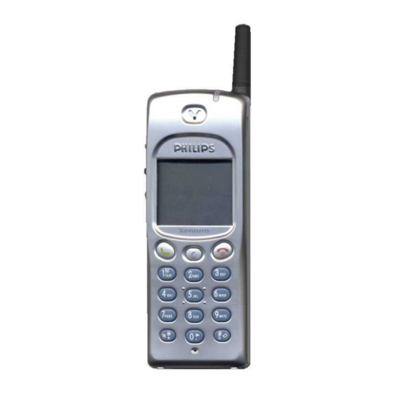
PHILIPS Philips Consumer Communications CUSTOMER SERVICES PCC/VY/691/E/XENIUMDB989LVL1/0025/MLD/MLD SERVICE REPAIR SUPPORT Revision : 2 Author : Fabrice TANT PROCEDURE Approval : Jean Pierre HOLLANDE Date : 19/06/2000 Operational manager Page 6 out of 24 7.0 BEFORE STARTING Description of the transceiver... -
Page 7: Description Of The Display
PHILIPS Philips Consumer Communications CUSTOMER SERVICES PCC/VY/691/E/XENIUMDB989LVL1/0025/MLD/MLD SERVICE REPAIR SUPPORT Revision : 2 Author : Fabrice TANT PROCEDURE Approval : Jean Pierre HOLLANDE Date : 19/06/2000 Operational manager Page 7 out of 24 Description of the display Indicates the Network on which your phone is registered. -
Page 8: Using The Carousel
Using The Carousel The carousel is a circular loop of icons displayed on the screen. These icons provide access to the different menus and sub menus used to operate your phone. Inserting the MICRO-SIM card 7.4.1 The mobile supports only the mini “plug-in” SIM card. Push the metal retaining clip to the right and lift the cardholder. -
Page 9: Inserting On The Battery
Inserting on the battery 7.5.1 Place the battery on the back of the phone (connectors downward, the top near the arrow inside the case). 7.5.2 Then push the battery into place in the direction of the antenna. Removing the battery 7.6.1 Press the locking button located alongside the antenna while pushing the battery in the direction of the arrow. -
Page 10: Test Procedures
7.7.3 Plug the transformer unit into the main AC power sockets. 7.7.4 The battery charge symbol indicates the state of the charge process : • Bars moving means the battery is being charged • Steady means the battery is fully charged If the battery is totally discharged, the battery icon will show and start scrolling 2 to 3 minutes only after connecting to the charger. - Page 11 Press Key 5 Checkerboard 1 pixel on (Checkerboard test) Press Key 5 again Left corner displays 5 Press Key 6 Checkerboard 2 pixel on (Inverted Checkerboard) Press Key 6 again Left corner displays 6 Press Key 7 All pixels and hard icons on Press key 7 again Left corner displays 7 Press key 8 (Eeprom...
- Page 12 Press # (FA Status) "FA/12NC” FA GOOD (Must be good) X XXXXXXXXXXX (12NC) Press # again Left corner displays # Press C Key without Test Press C again Left corner displays C Go to the UP with the User Melody Scanswitch (Melody Test) Go to the UP again...
-
Page 13: Rf Test
RF TEST 8.2.1 The Test SIM Card “SP” must be inserted into the phone before starting the tests. 8.2.2 Set the equipment as shown on the picture in chapter 6.2. 8.2.3 Set in the offset field of the radio tester a – 0.3 dBm lose for GSM Test 8.2.4 The following operations must be done: Synchronization/Registration... - Page 14 Output Power Average 1, 62, 124 Level 15 11.2 dBm to 14.8 dBm 1, 62, 124 Level 10 21.2 dBm to 24.8 dBm 1, 62, 124 Level 5 31 dBm to 34.1 dBm RECEPTION Rx Level 1, 62, 124 -83 dBm +/-2.5 dBm Rx Level 1, 62, 124...
-
Page 15: Charging Ign (Ignition) - Battery
SENSITIVITY BER at -85dbm 512,635,760,885 FER at -85dbm BER at -103dbm 2.44% FER at -103dbm If a phone is out of the specifications, it must be sent to the Repair Center. Charging IGN (Ignition) – Battery 8.3.1 Plug the connector of the charger into the round socket set at the base of the transceiver. The battery symbol should indicate the state of the charge process : •... -
Page 16: Assembly 10.0 Defaults Settings
Dismantlement 9.1.1 Unscrew the ANTENNA 9.1.2 Take the product, remove BATTERY 9.1.3 Remove the SIM card Assembly 9.2.1 Check the REAR HOUSING on the product 9.2.2 Check the LABEL on the back 9.2.3 Screw the ANTENNA 10.0DEFAULTS SETTINGS 10.1 Reset customer parameters. To reset customer parameters, it must use a GSM String. -
Page 17: Solutions In Case Of Problems During The Tests
11.0SOLUTIONS IN CASE OF PROBLEMS DURING THE TESTS If for any reasons the phone needs to be disassembled (on level 2 only) to fix a defect detected during the test procedure, a complete functional test and a RF test must be done. 11.1 The phone does not switch on. -
Page 18: Display Problems
- If the test SIM card can be detected but the message “SIM Failure” remains on the customer’s card, his card must be damaged. Ask him to contact his network operator. Otherwise send the mobile for repair 11.4 Display problems Contrast, icons and matrix of the display can be checked with the test SIM card by pressing keys ”5”, “6”... - Page 19 4311 257 61141 Antenna ass’y X16 DB 0906 4311 258 72846 Battery Slim 800mAh (Li-on) 4311 258 75075 Vibra Battery (900 mAh Li-on) 3122 427 20946 Fast Charger Europe 3122 427 21206 Fast Charger UK ANNEXE 1...
- Page 20 Each returned product must have an IRIS code to identify the failure.
Need help?
Do you have a question about the Xenium Dual Band and is the answer not in the manual?
Questions and answers