Table of Contents
Advertisement
Quick Links
Advertisement
Table of Contents

Related Manuals for Kathrein UFD 505


Summary of Contents for Kathrein UFD 505
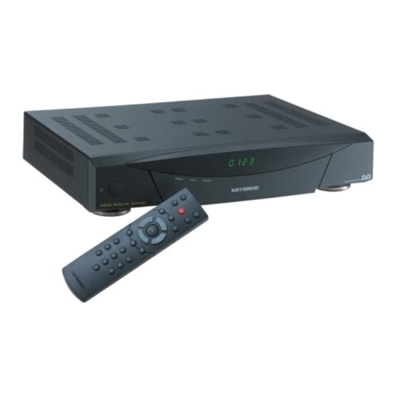
- Page 1 Operating Manual Order no.: 260 494...
-
Page 3: Safety Instructions
We wish you a great reception and much enjoyment with your new satellite re- ceiver. Your, KATHREIN-Team If you have any unexpected problems with your receiver, please contact your spe- cialist supplier through our hotline. Tel: (08031) 18 47 00... -
Page 4: Table Of Contents
Safety Instructions Contents Preface ...3 Contents ...4 Safety Instructions ...7 Important notes regarding operation ...7 Extended absence / thunderstorms... 7 Mains lead ... 7 Cleaning ... 7 Children-at-play ... 7 Repairs ... 7 Connections... 7 Place of installation... 8 Ventilation... 8 Humidity, exposure to sunlight, heat ... - Page 5 Safety Instructions Programme overview ...22 EPG ...22 Full EPG...22 EPG timer programming... 22 Sound settings...23 Setting the volume ...23 Stereo and two-channel sound reproduction...23 AC3 ...23 Programme lists...24 Selecting programmes last received ...24 Favourite programmes...24 To sort the channels ...25 To delete a programme ...25 To add a programme manually...26 Satellites add/remove...28...
- Page 6 Safety Instructions Remote frequency... 40 UFO micro... 40 Factory setting ... 41 Video recorder connection ...42 Recording ...42 Playback ...42 Software and programme lists update ...43 Data transfer from receiver to receiver ...44 Preparation ...44 Transferring programme lists ... 44 Transferring operating software ...
-
Page 7: Safety Instructions
Safety Instructions Safety Instructions Important notes regarding operation The following section contains important information relating to the operation, place of installation and connecting-up of the receiver. Read these notes carefully before putting the unit into operation. Extended absence / thunderstorms Always switch the unit off via its mains switch (at front left on unit) during periods of extended absence or at the onset of thunderstorms. -
Page 8: Operating Elements, Displays And Connections
Operating elements, displays and connections Important notes for siting and installation. Place of installation Every electronic device generates heat. The rise in temperature, however, lies within a safe range. Slight colour changes may occur to sensitive furniture surfaces and veneers over the course of time due to the constant effect of heat. In conjunc- tion with treated furniture surfaces, the unit’s rubber feet can likewise give rise to changes in colour. -
Page 9: Operating Elements, Displays And Connections
Satellite IF signal input Output of the LNB supply voltage and con- trol signals (22-kHz and DiSEqC 1.1) Satellite IF signal output Output for a analogue secondary receiver. The Sat IF signal is looped through. Mains voltage supply line UFD 505 260494... -
Page 10: Remote Control Handset Keys
Operating elements, displays and connections Remote control handset keys Switch over of the remote control Calls up favourite categories Programme information Calls up programme list Programme selec- tion / Selection of submenus and menu entries Mute (On/Off) 1...2 Numerical input for programmes, parental lock, LO frequency etc. -
Page 11: Connection And Putting Into Operation
Connection and putting into operation Remote control features The remote control features 2 command sets, making it possible to operate 2 receivers independently of each other in one room (not together with a twin receiver). Note For this purpose, program one receiver on the command set 1 and the second receiver on the command set 2. -
Page 12: Menu Concept
Connection and putting into operation Menu concept Note: Coloured backgrounds are used to emphasise the selected menus, submenus and menu items as well as the parameters to be set. The menus are to a large extent self-explanatory. You will find information relating to the selected menu point in the information box displayed under the menu. -
Page 13: Alphanumeric Assignments Of Number Buttons On The Remote Control
Operating instructions Alphanumeric assignments of number buttons on the remote control Button Language selection- OSD To select the language for the on-screen menus press: M C ou C The available languages are German, English, French, Italian, Span- ish, Portuguese, Dutch, Greek and Turkish. SPACE C -+ C menu language... -
Page 14: Connection And Putting Into Operation
Operating instructions Connection and putting into operation The following section is specifically intended for the specialist dealer. You only need to read this section if you are carrying out the installation yourself. You will find sample configurations in the section "Connection examples". First carry out all installation work before connecting the receiver to the mains power supply. -
Page 15: Lnb-Supply Voltage
If the feed system (LNB) is powered by an external supply voltage and the LNB supply voltage is not used for switching over polarity (e.g. Kathrein feed system UAS 330), the LNB supply of the receiver must be set to "OFF" (see section "Installation menu, LNB configuration“). -
Page 16: First Time Operation
Operating instructions First time operation The first steps Connect the receiver to the mains power supply. Switch on the receiver by pressing the power button at the front of the unit. You will see "- - - -“ in the LED display, afterwards "0000." The operation indicator LED lights red, the receiver is now in standby mode. -
Page 17: Programme Selection
Programme selection On-screen displays On Screen Display Important on-screen displays The receiver functions are controlled by a microprocessor and extensive software. The following explanations are intended to improve understanding of all proce- dures and to minimise the risk of mistakes. TV channel identifier The film symbol indicates a TV channel with the selected programme shown next to it and whether teletext is received. -
Page 18: Radio Programme List
Programme selection the programme is normally scrambled. The required programme can be selected with the bar cursor and confirmed by pressing the Radio programme list See above. The same applies to the radio programme list. Programme selection This section describes how you select analogue and digital TV programme with your receiver and how you can set the required volume. -
Page 19: On-Screen Displays On Screen Display
On-screen displays On Screen Display Selecting a TV programme by number entry You can select a different TV programme during a current TV programme by enter- ing the programme location number. Use the number buttons cations. Example You wish to select the TV channel "DSF". This programme is stored under the pro- gramme location number 015. -
Page 20: Selecting A Radio Programme By Number Entry
On-screen displays On Screen Display programme and by pressing the enter-in the channel number with the buttons on the remote control. Confirm your programme selection by pressing the programme list and remain in the programme already set. Selecting a radio programme by number entry You can select a different radio programme during a current radio programme by entering the programme location number. -
Page 21: Timer-Settings
Timer-settings Timer-settings You can use the timer for recording a programme with a video recorder on time. Seven timers are available which you can set to different programmes as well as start and end times. cursor to the timer you require and confirm it by pressing timer again. -
Page 22: Programme Overview
Programme overview Programme overview Full EPG EPG timer programming With the button, you receive an overview of the programmes (see on-screen display) currently received from the transponder with time and duration, provided that they are broadcast with electronic programme guide (EPG), for example, with ARD and ZDF. -
Page 23: Sound Settings
Sound settings Sound settings Setting the volume on the screen to show the set volume. Stereo and two-channel sound reproduction in the box on the right. Press the b utton to call up the audio menu for sound and language selection. -
Page 24: Programme Lists
Programme lists Programme lists The programmes /channels set at the factory can be changed in the " programme list" menu. Select the menu by pressing the well as tered. Selecting programmes last received Press the The arrows correspond to the cursor buttons gramme can then be selected by pressing these buttons. -
Page 25: To Sort The Channels
Programme lists To sort the channels You can sort programmes as desired. The programmes are sorted by shifting the entries in the programme lists. select the item "E", confirm your selection with channel will be highlighted by a coloured bar in the list. The bar can be moved page-by-page or line-by-line with the line can now be "captured"... -
Page 26: To Add A Programme Manually
Programme lists The highlighted line can bow be prepared for deletion by pressing the The control programme now asks: "Do you want to delete this channel?" To add a programme manually Basically follow the same procedure for sorting in order to add a channel. Press the main menu button Select "programme list"... - Page 27 Programme lists Only alphanumerical and decimal entries are accepted at the positions · name, · video PID (programme identification), · audio PID, · PCR PID (PCR = Programme Clock Reference) and · audio PID dig. Incorrect PID entries are rejected with the displayed message. incorrect parameter Press the your changes have been saved and the information display of the programme cur-...
-
Page 28: Satellites Add/Remove
Satellites add/remove Satellites add/remove Setting up a satellite The LNB can naturally also accommodate new satellites. For this, the orbit position that you need to take a bearing on must be known. The “Antenna settings“ menu entry in the installation menu can be used as an aid for alignment of the antenna. -
Page 29: Password
This is useful for identification in case of theft. See section "operating instructions" for information on how to use the numerical buttons on the remote control for alphanumerical entry. The factory setting is „UFD 505“. You have now undertaken all the settings for safeguarding and identifying your satellite receiver. - Page 30 Password Here, use the Using the dio list. Confirm your selection with The desired programme is now displayed on the screen. Use the and the line with the currently running programme is highlighted in the list with a yellow bar. Use the Using the bol.
-
Page 31: Operation From The Front Panel
Operation from the front panel Operation from the front panel If you have misplaced the remote control or the batteries are empty, you can still operate you receiver from the front panel. Backup operation On the front panel, there are 6 buttons at your disposal. The On/Off button, menu, select, and the cursor buttons with horizontal and vertical arrows. -
Page 32: Setting System Parameters
Setting system parameters Setting system parameters The following settings should not be altered without good reason, since they are factory presets or operational settings, matched specifically to your receiving sys- tem. Only extensions to the receiving systems or modifications call for new settings. The selected menus, submenus, entries, and parameters are highlighted. -
Page 33: Summer Time
Setting system parameters Summer time See above. Changeover in spring or fall. Confirm by pressing TV type Use the · PAL, · Multi-standard · NTSC unit Confirm by pressing Picture format Use the · 4 : 3 format or · 16 :9 format. -
Page 34: Osd Colour
Setting system parameters OSD colour Use the Confirm by pressing OSD trans Use the Confirm by pressing buttons to select the background colour of the on-screen display. two times. buttons to select the transparency of the background colour. two times. -
Page 35: Installation Menu
Installation menu Installation menu You should not change the following settings without good reason as they repre- sent factory settings or operational settings that are adapted to your receiving sys- tem. New settings are only required when changes or expansions are made to the re- ception system. -
Page 36: Changing The Oscillator Frequency
Installation menu Changing the oscillator frequency Move over to the right-hand side in the LNB configuration menu by pressing and the setting for LO High will be highlighted in colour. Using the number buttons, you can now enter a frequency matching your system. The same also applies for the LO Low setting. -
Page 37: Diseqc Setting
Installation menu DiSEqC setting The precondition for this setting is that you have made no changes in the DiSEqC (UFO) set-up, refer to the section "DiSEqC (UFO) Set-up". When you are in the LNB configuration menu (see above), press the buttons to move the coloured bar to the "HotBird"... -
Page 38: Tp Set-Up/Search
Installation menu existing programme list. You can interrupt the search by pressing the TP set-up/search Transponder selection The following settings are now possible (select positions with The shown on-screen display appears as the result of the search. Exit this menu by pressing (here ZDF). -
Page 39: Diseqc (Ufo) Set-Up
Installation menu After an unsuccessful search the following message appears: All new programmes are added to the existing programme list. Under the menu item „Delete TP“ you can remove the transponder from the pro- gramme memory by pressing to remove the transponder before it is deleted. DiSEqC (UFO) Set-up You should only make changes in this menu when the receiver is to be connected Therefore, take particular note of the information relating to your Sat-IF system. -
Page 40: Tone Burst
The setting under this menu point is also designed for operation of the receiver to- gether with a processing system. Control and communication between the receiver and the Kathrein UFO micro sys- tem takes place on the return of the coaxial cable. -
Page 41: Factory Setting
Installation menu A remote frequency must not be set in this operating mode, because it is defined by the UFO micro system as part of the addressing procedure. You will need to delete the previously allocated address when using the receiver for the first time together with a UFOmicro receiving system. -
Page 42: Video Recorder Connection
Installation menu Video recorder connection The connection diagram provided at the end of this User's Guide and the descrip- tion of the video recorder will show you how you should connect your video re- corder to the receiver. Recording In order to make a VCR recording, the satellite receiver must be switched on or the timer must be pre-programmed (see section "Timer settings“). -
Page 43: Software And Programme Lists Update
Observe the on-screen display! After a software update, you must set the time again! The updates are also available in the internet under the address: www.esc-kathrein.de/download/ufd/. Here, you will also find instructions for downloading. , the... -
Page 44: Data Transfer From Receiver To Receiver
In all cases wait until the "Succ." or "F * * *“ message appears on the display. You can download new operating software as well as a new channel list at our website Refer to the section "System information" to establish the status of your receiver. www.kathrein.de where you will also find the corresponding instructions. -
Page 45: Technical Annex
Installation menu Technical annex Technical features The receiver UFD 505 is equipped with the following features: · Reception of all digital TV channels (free-to-air receiver) · Reception of all DVB radio channels (free-to-air receiver) · Loop-through Sat IF input ·... -
Page 46: Technical Data
Technical annex Technical data RF features Sat-IF frequency range Input level range IF frequency Receiving threshold (Eb/No dig.) Sat-IF input Input impedance Video Modulation, FEC, demultiplexer Video resolution Frequency range Input data rates Video decoding Bit rate Output voltage Audio Audio decoding Bit rate Frequency range... -
Page 47: Accessories
Technical annex Accessories 1 Infrared remote control 2 Batteries 1.5 V, type: LR 03, size: AAA (Micro) 1 SCART cable 1 Set of operating instructions Scart socket assignments Signal Audio output, right Audio input, right Audio output, left Audio earth Blue earth Audio input, left Blue signal... -
Page 48: Connection Examples
Technical annex Connection examples Connection arrangement 1: DVB-Receiver UFD 505 UHF/VHF Connection of the DVB-S receiver to a TV set, a VCR and a hi-fi system for receiv- ing and recording digital satellite TV and radio channels. The digital sound output can be connected to a Dolby Digital System. -
Page 49: Connection Arrangement 2
Technical annex Connection arrangement 2: DVB-Receiver UFD 505 VHF/UHF Connection of a DVB receiver to an analogue Sat receiver and the complete TV and hi-fi system. The digital sound output can be connected to a Dolby Digital Sys- tem. The roof antenna connected via the video recorder to the TV permits the reception and recording of terrestrial programmes. -
Page 50: Glossary, Abbreviations
Technical annex Glossary, abbreviations Audio output AV channel slot Decoder DiSEqC Eb/No [dB] Eb/No ratio LED-Display Mute Pay-TV PCMCIA Receiver Satellite-IF signal SCART cable Standby S-VHS Symbol rate Timer function Transponder VCR connection Viterbirate Receiver sound output Preferential channel location of TV set for SCART input Decoder Unscrambling unit for pay-TV Control system between receiver and LNB, multi-switch Digital Video Broadcasting... -
Page 51: Short Technical Lexicon
Short technical lexicon Audio Coding MPEG 2/Layer 3 – the coded digital sound signal for Dolby Digital. It transmits 5 sound channels and one reduced sound channel for the subwoofer. DiSEqC DiSEqC (Digital Satellite Equipment Control) is a communication system between the Sat receiver (master) and the peripheral Sat components (slaves), such as LNBs, multi-switch, motorised antenna systems. -
Page 52: Symbol Rate
Short technical lexicon transponder transmit frequency, the polarisation (horizontal or vertical), the symbol rate and the viterbirate or error rate. Symbol rate The symbol rate describes the amount of data transmitted per second. The symbol rate is measured in MSymbols/s and is equal to the number of symbols that are re- ceived per second. -
Page 53: Service
Service Service OSD-Language German Satellite 1 Satellite: LO1: 9750 LO2: 10600 Satellite DiSEqC menu 22-kHz: Tone burst: DiSEqC DiSEqC repeat UFOmini Remote frequency UFOmicro Other settings Picture format 16:9 Satellite 2 Satellite: LO1: 9750 LO1: 10600 Satellite High/low PosA/B High/low PosA/B _____MHz LNB supply... - Page 54 KATHREIN-Werke KG ž Telephone (0 80 31) 18 40 ž Fax (0 80 31) 18 43 06 Anton-Kathrein-Straße 1-3 ž Postfach 10 04 44 ž D-83004 Rosenheim...
Need help?
Do you have a question about the UFD 505 and is the answer not in the manual?
Questions and answers