Fluke 51 User Manual
Series ii
Hide thumbs
Also See for 51:
- Service manual (28 pages) ,
- User manual (20 pages) ,
- Product overview (13 pages)
Table of Contents
Advertisement
Advertisement
Table of Contents

Related Manuals for Fluke 51


Summary of Contents for Fluke 51
-
Page 1: Users Manual
® 51 & 52 Series II Thermometer Users Manual English September 1999 Rev.1, 6/01 © 1999-2001 Fluke Corporation, All rights reserved. Printed in USA All product names are trademarks of their respective companies. Downloaded from Elcodis.com electronic components distributor... - Page 2 Limited Warranty & Limitation of Liability This Fluke product will be free from defects in material and workmanship for 3 years from the date of purchase. This war- ranty does not cover fuses, disposable batteries or damage from accident, neglect, misuse or abnormal conditions of opera- tion or handling.
-
Page 3: Table Of Contents
Table of Contents Title Page Introduction ........................1 Contacting Fluke ....................... 1 Getting Started....................... 4 Components......................5 Display Elements ...................... 6 Buttons........................7 Using the Thermometer ....................9 Changing Setup Options....................9 Entering or Exiting Setup ..................9 Setup Options ......................9 Changing a Setup Option.................. - Page 4 51 & 52 Series II Users Manual Maintenance........................13 Replacing the Batteries ..................... 13 Cleaning the Case and Holster.................. 13 Calibration ......................... 13 Specifications ......................... 13 Environmental......................13 General........................14 80 PK-1 Thermocouple (supplied with thermometer) ..........14 Electrical........................14 Replacement Parts and Accessories................
-
Page 5: Introduction
Contacting Fluke Introduction To order accessories, receive assistance, or locate the The Fluke Model 51 and Model 52 Thermometers (“the nearest Fluke distributor or Service Center, call: thermometer”) are microprocessor-based, digital thermometers designed to use external J-, K-, T-, and E-... - Page 6 51 & 52 Series II Users Manual Table 1. Safety Information WWarning A Warning identifies conditions and actions that pose hazards to the user. To avoid electrical shock or personal injury, follow these guidelines: • Before using the thermometer inspect the case. Do not use the thermometer if it appears damaged. Look for cracks or missing plastic.
- Page 7 51 & 52 Series II Introduction Table 1. Safety Information (cont.) WWarning (cont.) • Model 52: Measurement errors may occur if voltages on the measurement surfaces result in potentials greater than 1 V between the two thermocouples. When potential differences are anticipated between the thermocouples, use electrically insulated thermocouples.
-
Page 8: Getting Started
• Figure 2 and Table 4 describe the display. Everything in this Users Manual applies both to Models 51 and 52 unless otherwise indicated. • Table 5 describes the functions of the buttons. To become familiar with the thermometer, study the Then read the following sections. -
Page 9: Components
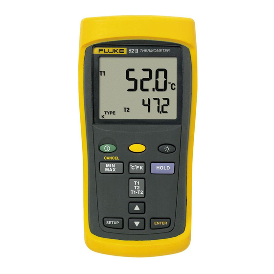
51 & 52 Series II Getting Started Components Table 3. Components Thermocouple T1 input Model 52: Thermocouple T2 input Holster Display Buttons Battery door Batteries aas01f.eps Figure 1. Components Downloaded from Elcodis.com electronic components distributor... -
Page 10: Display Elements
51 & 52 Series II Users Manual Display Elements Table 4. Display Elements The thermocouple measurement includes an offset. See "Changing Setup Options." The displayed readings do not change. A shift function is in progress. Setup is in progress. Low battery. Replace the batteries. -
Page 11: Buttons
51 & 52 Series II Getting Started Buttons Table 5. Buttons Press to turn the thermometer on or off. Press (CANCEL) to stop displaying the minimum, maximum, and average readings in the secondary display. (Shift function) Press to turn the backlight on and off. The backlight turns off after 2 minutes without any button presses. - Page 12 51 & 52 Series II Users Manual Table 5. Buttons (cont.) Press D to start or exit Setup. (See "Changing Setup Options.") Press K to scroll to the Setup option you want to change. Press K to increase the displayed setting.
-
Page 13: Using The Thermometer
51 & 52 Series II Using the Thermometer Entering or Exiting Setup Using the Thermometer When the thermometer is in Setup mode, the display Plug the thermocouple(s) into the input connector(s). shows s. Press to turn on the thermometer. •... -
Page 14: Changing A Setup Option
51 & 52 Series II Users Manual Changing a Setup Option Sleep mode: The thermometer enters sleep mode if no button Press to scroll to the setup option you press occurs for 20 minutes. Pressing any button want to change. -
Page 15: Measuring Temperatures
51 & 52 Series II Measuring Temperatures Notes Measuring Temperatures The display shows "- - - -" when a thermocouple Connecting a Thermocouple is not connected. To change the thermocouple type, see “Changing Setup The display shows 0L (overload) when the Options.”... -
Page 16: Holding The Displayed Readings
51 & 52 Series II Users Manual Holding the Displayed Readings Using the Offset to Adjust for Probe Errors Press to freeze the readings on the display. Use the offset option in Setup to adjust the thermometer’s The display shows H. -
Page 17: Maintenance
Refer to the safety information in Table 1 before replacing thermometer annually, starting one year after purchase. the batteries. To calibrate the thermometer, contact Fluke for the Turn off the thermometer if necessary. Service Center nearest you or follow the calibration procedure in the service manual listed in "Replacement... -
Page 18: General
51 & 52 Series II Users Manual General 80 PK-1 Thermocouple (supplied with thermometer) Weight 280 g (10 oz) Type Type K, Chromel Alumel, bead style 2.8 cm × 7.8 cm × 16.2 cm Dimensions −40 C to +260 (1.1 in × 3 in × 6.4 in) -
Page 19: Replacement Parts And Accessories
51 & 52 Series II Replacement Parts and Accessories Electrical (cont.) Replacement Parts and Accessories J-, K-, T-, and E-type: ±[0.05 % of Measurement Accessory Part Number reading + 0.3 Accuracy, T1, C (0.5 [below −100 T2, or T1-T2 C (−148 F): add 0.15 %... - Page 20 51 & 52 Series II Users Manual Downloaded from Elcodis.com electronic components distributor...
Need help?
Do you have a question about the 51 and is the answer not in the manual?
Questions and answers