Fluke 51 II Series User Manual
Hide thumbs
Also See for 51 II Series:
- Specifications (1 page) ,
- Service manual (28 pages) ,
- User manual (20 pages)

Related Manuals for Fluke 51 II Series


Summary of Contents for Fluke 51 II Series
- Page 1 ® 51 & 52 Series II Thermometer Users Manual Fluke-Direct .com info@Fluke-Direct.com 1.888.610.7664...
- Page 2 Limited Warranty & Limitation of Liability This Fluke product will be free from defects in material and workmanship for 3 years from the date of purchase. This war- ranty does not cover fuses, disposable batteries or damage from accident, neglect, misuse or abnormal conditions of opera- tion or handling.
-
Page 3: Table Of Contents
Table of Contents Title Page Introduction ........................1 Contacting Fluke......................1 Getting Started ....................... 4 Components ......................5 Display Elements....................... 6 Buttons ........................7 Using the Thermometer....................9 Changing Setup Options ....................9 Entering or Exiting Setup ................... 9 Setup Options......................9 Changing a Setup Option .................. - Page 4 Replacing the Batteries ..................... 13 Cleaning the Case and Holster ................. 13 Calibration......................... 13 Specifications......................... 13 Environmental ......................13 General ........................14 80 PK-1 Thermocouple (supplied with thermometer) ..........14 Electrical ........................1 4 Replacement Parts and Accessories ................15 Fluke-Direct .com info@Fluke-Direct.com 1.888.610.7664...
-
Page 5: Introduction
51 & 52 Series II Introduction The Fluke Model 51 and Model 52 Thermometers (“the thermometer”) are microprocessor-based, digital thermometers designed to use external J-, K-, T-, and E- type thermocouples (temperature probes) as temperature sensors. Use the thermometer only as specified in this manual. - Page 6 • Reflective objects result in lower than actual temperature measurements. These objects pose a burn hazard. • Do not operate the thermometer around explosive gas, vapor, or dust. • Do not connect to voltages > 30 V ac rms, 42 V pk, 60 V dc from earth ground. Fluke-Direct .com info@Fluke-Direct.com 1.888.610.7664...
- Page 7 • Do not attempt to recharge the batteries. • To prevent explosion, do not throw batteries into a fire. • Follow local laws or regulations when disposing of batteries. • Match the + and − polarities of the battery with the battery case. Fluke-Direct .com info@Fluke-Direct.com 1.888.610.7664...
-
Page 8: Getting Started
Everything in this Users Manual applies both to Models 51 and 52 unless otherwise indicated. • Table 5 describes the functions of the buttons. To become familiar with the thermometer, study the Then read the following sections. following: Fluke-Direct .com info@Fluke-Direct.com 1.888.610.7664... -
Page 9: Components
51 & 52 Series II Getting Started Components Table 3. Components Thermocouple T1 input Model 52: Thermocouple T2 input Holster Display Buttons Battery door Batteries aas01f.eps Figure 1. Components Fluke-Direct .com info@Fluke-Direct.com 1.888.610.7664... -
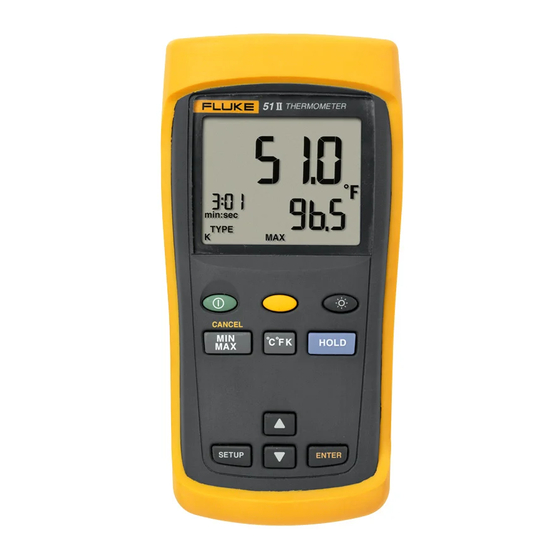
Page 10: Display Elements
Model 52: T1, T2, or T1-T2 reading. The temperature unit. aas02f.eps Figure 2. Display Elements Secondary Display: MAX, MIN, AVG, or offset. Model 52: T1 or T2 reading. The thermocouple type. Time Display: The elapsed time. Fluke-Direct .com info@Fluke-Direct.com 1.888.610.7664... -
Page 11: Buttons
when turning on the thermometer to test the display. All display elements appear. Model 52: Press to toggle showing the T1, T2, and T1-T2 (differential temperature measurement) in the primary or secondary display. Fluke-Direct .com info@Fluke-Direct.com 1.888.610.7664... - Page 12 Press to scroll to the Setup option you want to change. Press to decrease the displayed setting. Press to enter a Setup option. Press again to store the displayed setting in memory. Fluke-Direct .com info@Fluke-Direct.com 1.888.610.7664...
-
Page 13: Using The Thermometer
(sleep mode on) or settings reset only when the batteries are removed for (sleep mode off) more than 2 minutes. Line Frequency 50 H (50 Hz) or 60 H (60 Hz) Fluke-Direct .com info@Fluke-Direct.com 1.888.610.7664... -
Page 14: Changing A Setup Option
Remember to reset the offset to 0.0 when it is no longer needed. The offset automatically resets to 0.0 when you change the thermocouple type. Model 52: You can store individual offsets for T1 and T2. Fluke-Direct .com info@Fluke-Direct.com 1.888.610.7664... -
Page 15: Measuring Temperatures
Hold or attach the thermocouple(s) to the measurement location. The temperature reading appears in the primary display. Model 52: Press to toggle between showing the T1, T2, and T1-T2 readings in the primary or secondary display. Fluke-Direct .com info@Fluke-Direct.com 1.888.610.7664... -
Page 16: Holding The Displayed Readings
Allow the readings to stabilize. appears on the display. In Setup change the offset until the primary display Press (CANCEL) to exit MIN MAX mode. reading matches the calibration temperature. (See "Changing Setup Options.") Fluke-Direct .com info@Fluke-Direct.com 1.888.610.7664... -
Page 17: Maintenance
Refer to the safety information in Table 1 before replacing thermometer annually, starting one year after purchase. the batteries. To calibrate the thermometer, contact Fluke for the Turn off the thermometer if necessary. Service Center nearest you or follow the calibration procedure in the service manual listed in "Replacement... -
Page 18: General
Refers to the level of Impulse Withstand Voltage protection E-type: −150 C to +1000 provided. Category 1 products should not be attached to mains F to +1832 (-238 circuits. F / K <1000 Display F / K ≥1000 Resolution Fluke-Direct .com info@Fluke-Direct.com 1.888.610.7664... -
Page 19: Replacement Parts And Accessories
200 MHz in 1.5 V/m field, for 200 MHz CD-ROM 1276106 to 1000 MHz in 3 V/m field. Emmisions: Commercial Limits per Service Manual 1276123 EN50081-1 Maximum 1 V (Maximum voltage difference Differential between T1 and T2) Common Mode Voltage Temperature ITS-90 Scale Fluke-Direct .com info@Fluke-Direct.com 1.888.610.7664...
Need help?
Do you have a question about the 51 II Series and is the answer not in the manual?
Questions and answers