Table of Contents
Advertisement
This service information is designed for experienced repair technicians only and is not designed for use by the general public.
It does not contain warnings or cautions to advise non-technical individuals of potential dangers in attempting to service a product.
Products powered by electricity should be serviced or repaired only by experienced professional technicians. Any attempt to service
or repair the products dealt with in this service information by anyone else could result in serious injury or death.
TABLE OF CONTENTS
1. Safety Precautions.............................................3
2. Specification .......................................................5
2.1
CS-RE9JKE CU-RE9JKE ............................5
2.2
CS-RE12JKE CU-RE12JKE ........................7
2.3
CS-RE15JKE CU-RE15JKE ........................9
3. Features ............................................................11
4. Location of Controls and Components .........12
4.1
Indoor Unit..................................................12
4.2
Outdoor Unit ...............................................12
4.3
Remote Control ..........................................12
5. Dimensions .......................................................13
5.1
Indoor Unit..................................................13
5.2
Outdoor Unit ...............................................14
6. Refrigeration Cycle Diagram...........................15
7. Block Diagram ..................................................16
8. Wiring Connection Diagram............................17
Indoor Unit
CS-RE9JKE
CS-RE12JKE
CS-RE15JKE
WARNING
9. Printed Circuit Board .......................................19
10. Installation Instruction.....................................23
10.1
Select the Best Location ............................23
10.2
Indoor Unit..................................................24
10.3
Outdoor Unit ...............................................26
11. Service Mode ....................................................29
11.1
Auto OFF/ON Button ..................................29
11.3
12. Operation Control.............................................32
12.1
Basic Function............................................32
12.2
Indoor Fan Motor Operation.......................33
12.3
Outdoor Fan Motor Operation ....................33
13. Protection control ............................................36
13.1
Protection Control For All Operations ........36
Operation....................................................37
13.3
Outdoor Air Temperature Control...............38
© 2008 Panasonic Home Appliances Air-Conditioning
(Guangzhou) Co.,Ltd (PHAAG). All rights reserved.
Unauthorized copying and distribution is a violation of
law.
Order No: PHA-AG0902001C2
Outdoor Unit
CU-RE9JKE
CU-RE12JKE
CU-RE15JKE
Advertisement
Table of Contents

Related Manuals for Panasonic CS-RE9JKE


Summary of Contents for Panasonic CS-RE9JKE
-
Page 1: Table Of Contents
13.2 Protection Control For Cooling and Soft Dry 7. Block Diagram ..........16 Operation............37 8. Wiring Connection Diagram......17 13.3 Outdoor Air Temperature Control....38 © 2008 Panasonic Home Appliances Air-Conditioning (Guangzhou) Co.,Ltd (PHAAG). All rights reserved. Unauthorized copying and distribution is a violation of law. - Page 2 14. Troubleshooting Guide........40 14.1 Refrigeration Cycle System......40 14.2 Break Down self Diagnosis Function..40 15. Disassembly and Assembly Instructions ..43 16. Exploded View and Replacement Pars List...46 16.1 Indoor Unit ..........46 16.2 Outdoor Unit ..........48...
-
Page 3: Safety Precautions
1. Safety Precautions Read the following “SAFETY PRECAUTIONS” carefully before perform any servicing. Electrical work must be installed or serviced by a licensed electrician. Be sure to use the correct rating of the power plug and main circuit for the model installed. The caution items stated here must be followed because these important contents are related to safety. - Page 4 17. After completion of installation, confirm there is no leakage of refrigerant gas. It may generate toxic gas when the refrigerant contacts with fire. 18. Ventilate if there is refrigerant gas leakage during operation. It may cause toxic gas when the refrigerant contacts with fire.
-
Page 5: Specification
2. Specification CS-RE9JKE CU-RE9JKE Item Unit Indoor Unit Outdoor Unit Capacity 2.50(0.90~3.00) BTU/h 8530(3070~10230) 3.57(4.74~3.00) BTU/hW 12.18(16.16~10.23) Noise Level dB(A) Hi: 42 Lo: 27 QLo: 22 Hi: 47 Power level dB Capacity 3.30(0.90~4.10) BTU/h 11250(3070~13980) 4.02(5.29~3.57) BTU/hW 13.71(18.06~12.16) Noise Level... - Page 6 Item Unit Single Power Source (Phase, Voltage, Cycle) Input Power COOLING 700(190~1000) HEATING 820(170~1150) Starting Current 3.70 Running Current COOLING 3.45 HEATING 3.70 Maximum Current 6.00 Power Factor COOLING HEATING Power factor means total figure of compressor, indoor fan motor and outdoor fan motor. Power Cord Number of core 3 (1.5mm)
-
Page 7: Cs-Re12Jke Cu-Re12Jke
CS-RE12JKE CU-RE12JKE Item Unit Indoor Unit Outdoor Unit Capacity 3.50(0.90~3.90) BTU/h 11940(3070~13300) 3.47(5.29~3.25) BTU/hW 11.82(18.06~11.08) Noise Level dB(A) Hi: 42 Lo: 30 QLo: 22 Hi: 48 Power level dB Hi: 53 Lo: - Hi: 61 Capacity 4.25(0.90~5.10) BTU/h 14490(3070~17390) 3.79(6.00~3.49) BTU/hW 12.94(20.47~11.91) Noise Level... - Page 8 Item Unit Single Power Source (Phase, Voltage, Cycle) Input Power COOLING 1010(170~1200) HEATING 1120(150~1460) Starting Current 5.20 Running Current COOLING 4.70 HEATING 5.20 Maximum Current 6.80 Power Factor COOLING HEATING Power factor means total figure of compressor, indoor fan motor and outdoor fan motor. Power Cord Number of core 3 (1.5mm)
-
Page 9: Cs-Re15Jke Cu-Re15Jke
CS-RE15JKE CU-RE15JKE Item Unit Indoor Unit Outdoor Unit Capacity 4.20(1.00~4.60) BTU/h 14330(3410~15700) 3.33(4.76~2.87) BTU/hW 11.37(16.23~9.81) Noise Level dB(A) Hi: 46 Lo: 31 QLo: 29 Hi: 50 Power level dB Hi: 57 Lo: - Hi: 63 Capacity 5.30(0.90~7.60) BTU/h 18080(3070~25930) 3.44(4.28~3.16) BTU/hW 11.74(14.61~10.80) Noise Level... - Page 10 Item Unit Single Power Source (Phase, Voltage, Cycle) Input Power COOLING 1260 (210~1600) HEATING 1540 (210~2400) Starting Current 7.10 Running Current COOLING 6.05 HEATING 7.10 Maximum Current 9.70 Power Factor COOLING HEATING Power factor means total figure of compressor, indoor fan motor and outdoor fan motor. Power Cord Number of core 3 (1.5mm)
-
Page 11: Features
3. Features Inverter Technology Wider output power range Energy saving Quick Cooling More precise temperature control Long Installation Piping CS/CU-RE9/12/15JKE, long piping up to 15 meters. Easy to use remote control Quality Improvement Random auto restart after power failure for safety restart operation Gas leakage protection Prevent compressor reverse cycle Inner protector to protect compressor... -
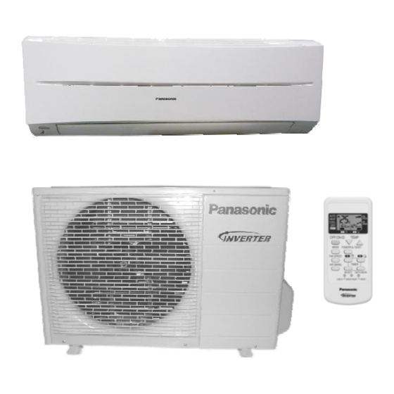
Page 12: Location Of Controls And Components
4. Location of Controls and Components Indoor Unit Front Panel GREEN Receiver POWER Vertical airflow Air Filter direction louver Horizontal airflow ORANGE TIMER direction louver INDICATOR GREEN QUIET Outdoor Unit POWERFUL Remote Control Transmitter Temperature OFF/ON setting Operation mode Fan speed Timer selection setting... -
Page 13: Dimensions
5. Dimensions Indoor Unit Unit mm Air intake Air outlet 12.5 404.6 119.3... -
Page 14: Outdoor Unit
Outdoor Unit Unit: mm... -
Page 15: Refrigeration Cycle Diagram
6. Refrigeration Cycle Diagram CS/CU-RE9JKE, CS/CU- RE12JKE COOLING CS/CU-RE15JKE HEATING... -
Page 16: Block Diagram
7. Block Diagram... -
Page 17: Wiring Connection Diagram
8. Wiring Diagram... -
Page 19: Printed Circuit Board
9. Printed Circuit Board Indoor Unit 9.1.1 Main Printed Circuit Board TOP VIEW... - Page 20 BOTTOM VIEW...
- Page 21 9.1.2 Indicator & receiver TOP VIEW BOTTOM VIEW...
- Page 22 Outdoor Unit 9.2.1 CU-RE9JKE, CU-RE12JKE TOP VIEW BOTTOM VIEW...
-
Page 23: Installation Instruction
10. Installation Instruction 10.1 Select the Best Location 11.1.3 Indoor/Outdoor Unit 10.1.1 Indoor Unit There should not be any heat source or steam near the unit. There should not be any obstacles blocking the air circulation. A place where air circulation in the room is good. A place where drainage can be easily done. -
Page 24: Indoor Unit
10.2 Indoor Unit 10.2.1 How to Fix Installation Plate The mounting wall is strong and solid enough to prevent if from the vibration. The centre of installation plate should be at more Wall Wall More than 450 mm More than 450 mm than 450 mm at right and left of the wall. - Page 25 10.2.3 Indoor Unit Installation...
-
Page 26: Outdoor Unit
10.2.4 Connect the Cable to the Indoor Unit The inside and outside connecting cable can be connected without removing the front grille. Connecting cable between indoor unit and outdoor unit shall be approved polychloroprene sheathed 4x 1.5mm flexible cords, type designation 245 IEC 57 or heavier cord. ‹... -
Page 27: Evacuation Of The Equipment
10.3.2.2 Cutting and flaring the piping Please cut using pipe cutter and then remove the burrs. Remove the burrs by using reamer. If burrs are not removed, gas leakage may be caused. Turn the piping end down to avoid the metal powder entering the pipe. Please make flare after inserting the flare nut onto the copper pipes. - Page 28 10.3.4 Connect the cable to the Outdoor Unit Remove the control board cover from the unit by loosening the screw. Connecting cable between indoor unit and outdoor unit shall be approved polychloroprene sheathed 4x 1.5mm flexible cord, type designation 245 IEC 57 or heavier cord. Secure the cable onto the control board with the holder (clamper).
-
Page 29: Service Mode
11. Service Mode 11.1 Auto OFF/ON Button Auto OFF/ON Button Pressed 1. AUTO OPERATION MODE Once the Auto OFF/ON button is slightly pressed, the unit will immediately operate in Auto operation. This operation can be used to operate air conditioner with limited function if remote control is misplaced or malfunction. -
Page 30: Operate And Display Of Remote Control
11.3 Operate and Display of Remote Control 11.3.1 Original setting 11.3.2 Mode selecting button UTO, HEAT, COOL, DRY can be selected by pressing “MODE” button. Initial display of LCD is as follow *Keeping the button depressed continuously, the operation mode will change in the following order in turn AUTO—HEAT—COOL—DRY--AUTO 11.3.3 Temperature adjusting button Temperature adjusting range is between 16... - Page 31 11.3.7 Timer setting button There are 4 types of timer setting by pressing Timer setting button: ON-TIMER, OFF-TIMER, ON-OFF TIMER, OFF- ON TIMER. 1) SELECT button — When the air conditioner is ON, OFF-TIMER or OFF-ON TIMER can be selected by pressing SELECT button.
-
Page 32: Operation Control
12. Operation Control 12.1 Basic Function 12.1.1 Internal Setting Temperature Once the operation starts, remote control setting temperature will be taken as base value for temperature shifting processes. These shifting processes are depending on the air conditioner settings and the operation environment. The final shifted value will be used as internal setting temperature and it is updated continuously whenever the electrical power is supplied to the unit. -
Page 33: Indoor Fan Motor Operation
12.2 Indoor Fan Motor Operation Basic Rotation Speed Manual Fan speed Fan motor’s number of rotation is determined according to remote control setting. Remote control QUIET Model COOLING(rpm) 1200 1040 CS-RE9JKE HEATING(rpm) 1200 1080 COOLING(rpm) 1210 1110 1020 CS-RE12JKE HEATING(rpm) -
Page 34: Quiet Operation
1. Automatic vertical airflow direction can be set using remote control; the vane swings up and down within the angles as stated above. For heating mode operation, the angle of the vane depends on the indoor heat exchanger temperature. When the air conditioner is stopped using remote control, the vane will shift to close position. -
Page 35: Indication Panel
12.3.5 Automatic Restart Control When the power supply is cut off during the operation of air conditioner, the compressor will re-operate within three to four minutes after power supply resumes. 12.3.6 Indication Panel POWER TIMER Color Green Orange Light ON Operation ON Timer setting ON Light OFF... -
Page 36: Protection Control
13. Protection control 13.1 Protection Control For All Operations 13.1.1 Time Delay Safety Control The Compressor will not turn on within 3 minutes from the moment operation stops, although the unit is turned on again by pressing OFF/ON button at remote control within this period. This control is not applicable if the power supply is cut off and on again. -
Page 37: Protection Control For Cooling And Soft Dry Operation
13.1.6 Low pressure Prevention control (Gas Leakage Detection) 1. When the conditions listed in the table occur, the compressor stops and restarts after three minutes. 2. If this continuously occurs for twice within 20 minutes, all indoor and outdoor relays will be cut off. 3. -
Page 38: Outdoor Air Temperature Control
13.2.2 Freeze Prevention Control 1 .Frequency of the compressor For prevention of freezing of the indoor evaporator, the frequency of the compressor will be changed according to the indoor piping temperature. 2 .Indoor Fan Control Indoor fan speed changes according to the indoor piping temperature. 13.2.3 Dew Prevention Control •... - Page 39 Auto Fan Speed +15rpm/s Fixed Free 2. During heating operation, the indoor fan will run at the following speed when the compressor stops. 3. Hot Start When the heating operation starts, the indoor fan stops and the compressor run with the frequency of 117Hz. This is to prevent the cold airflow from blowing.
-
Page 40: Troubleshooting Guide
14. Troubleshooting Guide 14.1 Refrigeration cycle system In order to diagnose malfunctions, make sure that there are no Normal Pressure and Outlet Air Temperature (Standard) Gas Pressure Outlet air electrical problems before inspecting the refrigeration cycle. Such Temperature problems include insufficient insulation, problem with the power (kg/cm (°C) source, malfunction of a compressor and a fan. -
Page 41: Breakdown Self Diagnosis Function
14.1.2 Relationship between the condition of the air conditioner and pressure and electric current Cooling Mode Heating Mode Condition of the Electric current High High Electric current air conditioner Low Pressure during Low Pressure Pressure Pressure during operation operation Insufficient Ô... - Page 42 14.2.3 Error Codes Table...
-
Page 43: Disassembly And Assembly Instructions
15. Disassembly and Assembly Instructions WARNING High Voltage is generated in the electrical parts area by the capacitor. Ensure that the capacitor has discharged sufficiently before proceeding with repair work. Failure to heed this caution may result in electric shocks. Removal Procedure for Intake Grille 1. - Page 44 2. Pull out the front grille form the unit body. Removal Procedure for Main Electronic Controller 1. After front grille is taking off, remove the cover of control board and holder, then the Main PCB can be seen. 3. Drag out the supporting hook to the right side and pull up a bit the main PCB. Then release the lead wire connecting to CN-FM, CN-STM3, CN-DISP1-A, earth wire (Yellow/Green) and take out the sensor from the holder on evaporator.
- Page 45 Removal Procedure for Main Electronic Controller 1. Separate the drain hose and the drain plate. 2. Pull out the discharge grille slightly. Removal Procedure for Cross Flow Fan 1. Release fixing screws on both side, disassembly the fixing board from evaporator on the left side and pull out the whole evaporator.
-
Page 46: Exploded View And Replacement Pars List
16. Exploded View and Replacement Pars List 16.1 Indoor Unit CS-RE9JKE, CS-RE12JKE, CS-RE15JKE... - Page 47 PART NAME&DESCRIPTION CS-RE9JKE CS-RE12JKE CS-RE1 JKE CHASSIS COMPLETE CWD50C1616 CWD50C1616 CWD50C1616 FAN MOTOR ARW6102AC ARW6102AC ARW6102AC CROSS FLOW FAN COMPLETE CWH02C1080 CWH02C1080 CWH02C1080 EVAPORATOR CWB30C2811 CWB30C2811 CWB30C2994 AUXILIARY TUBE ASS'Y CWT01C4858 CWT01C4858 CWT01C4844 AIN PLUG CWH521096 CWH521096 CWH521096 DISCHARGE GRILLE COMPLETE...
-
Page 48: Outdoor Unit
16.2 Outdoor Unit CU-RE9JKE, CU-RE12JKE... - Page 49 PART NAME&DESCRIPTION Q'TY CU-RE9JKE CU-RE12JKE CHASSIS ASS'Y CWD50K2193A CWD50K2193A FAN MOTOR BRACKET CWD541123 CWD541123 SCREW-FAN MOTOR BRACKET CWH551148A CWH551148A FAN MOTOR CWA951654 CWA951656 SCREW-FAN MOTOR MOUNT CWH55406J CWH55406J PROPELLER FAN ASS'Y CWH03K1034 CWH03K1034 NUT-PROPELLER FAN CWH561036J CWH561036J COMPRESSOR CWB092256 CWB092256 ANTI-VIBRATION BUSHING CWH50077 CWH50077...
- Page 50 CU-RE15JKE...
- Page 51 PART NAME&DESCRIPTION Q'TY CU-RE JKE CHASSIS ASS'Y CWD50K2175A FAN MOTOR BRACKET CWD541123 SCREW-FAN MOTOR BRACKET CWH551148A FAN MOTOR ARS44E8P40AC SCREW-FAN MOTOR MOUNT CWH55252J PROPELLER FAN ASS'Y CWH03K1014 NUT-PROPELLER FAN CWH561034J COMPRESSOR CWB092398 ANTI-VIBRATION BUSHING CWH50077 NUT-COMPRESSOR MOUNT CWH56000J CONDENSER CWB32C2717 TUBE ASSY CWT024640 HOLDER COUPLING ASS'Y...
Need help?
Do you have a question about the CS-RE9JKE and is the answer not in the manual?
Questions and answers