
Subscribe to Our Youtube Channel
Related Manuals for GE Security ZP3


Summary of Contents for GE Security ZP3
- Page 1 Security ZP3 Fire Control Panel Installation, Commissioning and Maintenance Manual...
- Page 2 Trademarks and patents GE and the GE monogram are trademarks of General Electric Company. The ZP3 Fire Control Panel name and logo are trademarks of GE Security.
-
Page 3: Table Of Contents
ZP3 Fire Control Panel Installation, Commissioning and Maintenance Manual Table of contents Heading Page List of abbreviations and acronyms..........................x Associated publications and references ......................... x General warnings and precautions ..........................xi Primary supply..................................xi Back-up battery supply..............................xii Regulatory information................................xii Chapter 1: Installation overview............................1... - Page 4 ZP3 Fire Control Panel Installation, Commissioning and Maintenance Manual Good connections ................................43 Careful handling of electronics..........................43 Cleanliness..................................43 Neatness..................................... 43 Chapter 3: Field wiring................................45 Terminal layout..................................45 Power supply ..................................... 46 Mains supply..................................46 Auxiliary 24 VDC supply ..............................47 External power for accessory boards ........................
- Page 5 ZP3 Fire Control Panel Installation, Commissioning and Maintenance Manual System configuration: relays ............................ 75 System configuration: printer........................... 75 System configuration: [various]..........................76 Planner....................................77 Level 4 operations................................77 Chapter 5: System configuration ............................. 79 System specification ................................79 General information................................79 Input-output mapping..............................
- Page 6 ZP3 Fire Control Panel Installation, Commissioning and Maintenance Manual New data structure................................. 95 Compatibility with Maestro and Planner........................95 Peer-to-peer 3 (P2P3) protocol............................95 Overview....................................95 Compatibility with older versions of panel software ..................95 P2P3 New features................................96 Panel comms enable/disable ........................... 96 Inter-panel support for remote diagnostics across the network............
- Page 7 Figure 4: ZP3 Fire control panel - modular construction..................9 Figure 5: ZP3 Fire control panel – internal features....................10 Figure 6: ZP3 Fire control panel – main chassis assembly.................. 11 Figure 7: ZP3 Fire Control Panel - Door Assembly ....................13 Figure 8: ZP3 Fire control panel –...
- Page 8 ZP3 Fire Control Panel Installation, Commissioning and Maintenance Manual Figure 18: ZP3 Fire control panel – accessory plate ....................24 Figure 19: Mounting auxiliary boards ..........................25 Figure 20: ZP3AB-MD3 Modem ............................26 Figure 21: Installing the modem mounting bracket ....................27 Figure 22: Installing the modem............................
- Page 9 Table 27: Loop length cable size (various diameters) – assuming no high power devices ....109 Table 28: DC Cable Size...............................110 Table 29: ZP3 fire control panel – quarterly checks....................111 Table 30: ZP3 fire control panel – annual checks ....................113 Table 31: Keypad description............................114 Table 32: Device definition table and device type analogues interpretation...........122 Table 33: Analogue status –...
-
Page 10: List Of Abbreviations And Acronyms
ZP3 Fire Control Panel Installation, Commissioning and Maintenance Manual List of abbreviations and acronyms Table 1 lists and defines the abbreviations and acronyms used in this manual. Table 1: Abbreviations and acronyms Abbreviation Definition Direct Current Ground Liquid Crystal Display... -
Page 11: General Warnings And Precautions
Panel, and has been prepared in accordance with ZP3 operating software version 3.11. General warnings and precautions Trained service personnel must carry out procedures in this manual. The ZP3 panel is powered from a 230 VAC primary supply and from a 24 VDC battery backup supply. Primary supply WARNING: THE POWER SUPPLY FORMS PART OF THE MAIN BOARD ASSEMBLY. -
Page 12: Back-Up Battery Supply
Certification Certification body 1134 Certificate number 1134-CPD-089 Manufacturer GE Security Africa, 555 Voortrekkerroad, Maitland, Cape Town 7405, PO Box 181 Maitland, South Africa Manufacturer’s GE Security B.V., Kelvinstraat 7, 6003 DH Weert, The Netherlands representative (Europe) Page xii REV 11 (ISS 08/03/2010) -
Page 13: Chapter 1: Installation Overview
Chapter 1: Installation overview Introduction The ZP3 fire control panel (see Figure 1) is a state-of-the-art analogue addressable panel that complies with the EN54 parts 2 and 4 standards. It is a compact microprocessor controlled unit, of modular design. Hardware and software modules enable you to configure virtually any system requirement. -
Page 14: Specification
ZP3 Fire Control Panel Installation, Commissioning and Maintenance Manual Specification Refer to Table 4 for a detailed specification of the ZP3 Fire Control Panel. Table 4: ZP3 Fire control panel specification Description Specification/ Remarks parameters Specification Compliance Fire alarm panel... - Page 15 ZP3 Fire Control Panel Installation, Commissioning and Maintenance Manual Description Specification/ Remarks parameters Output Current Total continuous 2.6 A at 21 VDC See note 2 Total continuous 3.0 A at 24 VDC See note 2 Total peak 5.5 A at 24 VDC...
- Page 16 ZP3 Fire Control Panel Installation, Commissioning and Maintenance Manual Description Specification/ Remarks parameters Power supply (external) Primary supply 24 to 28 VDC, Optional - Supplied from an external charger (Amps dependant on system load) Output (mains OFF) 24 VDC 15 to 27.6 VDC depending upon state of battery and...
- Page 17 ZP3 Fire Control Panel Installation, Commissioning and Maintenance Manual Description Specification/ Remarks parameters Control buttons/keys Help Button Displays operator instructions on-screen View fire alarm Button Displays “Fire Alarms by Zone” screen View fault alarm Button Displays “Fault Alarms by Zone” screen...
- Page 18 ZP3 Fire Control Panel Installation, Commissioning and Maintenance Manual Description Specification/ Remarks parameters Zone pre-alarm Yellow Point pre-alarm Yellow System test mode Yellow Power on Green Switched outputs (standard) Sounder circuits Monitored sounder circuits, programmable as one o/p (Common/programmable) “1 + 2”...
-
Page 19: Dimensions
ZP3 Fire Control Panel Installation, Commissioning and Maintenance Manual Dimensions See Figure 2 for the dimensions of the ZP3 fire alarm panel. The basic panel is designed for surface mounting, and flush-mounting kits are available. The dimensions below apply to the basic panel. -
Page 20: Panel Overview
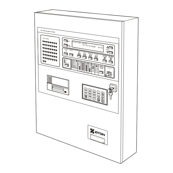
Panel overview Display and controls The fascia of the ZP3 fire panel has the necessary indicator lamps, text display screen, controls, menu keyboard, and printer to provide the operator with the status of the system at all times. It also has a reporting system for alarms, faults, and other events. Figure 3 shows the main features of the front panel. -
Page 21: Panel Construction
Panel construction Modular format The ZP3 fire control panel (see Figure 4) is of modular design so that it can be configured for any required application. It consists of a basic panel, which is fully functional, and available in 3 models, 1-loop, 2-loop, and 4-loop. -
Page 22: Internal Features
ZP3 Fire Control Panel Installation, Commissioning and Maintenance Manual Internal features Figure 5 shows the internal features of the basic ZP3 panel with additional detail. All components are carried on two main modules; the internal chassis holds the main board and processor board, and the door-assembly holds the display board, the zone board, the keyboard, and the Zport1 connection. -
Page 23: Main Chassis Assembly
ZP3 Fire Control Panel Installation, Commissioning and Maintenance Manual Main chassis assembly Figure 6 shows all the main features of the ZP3 panel main chassis assembly. This unit comprises the line-drivers, the I/O circuitry, the control circuits, the power supply, and the plug-in central processing unit (CPU). - Page 24 ZP3 Fire Control Panel Installation, Commissioning and Maintenance Manual Legend: Item Description Item Description Earth monitoring enabled Monitored sounder 2 Battery for time/date Main 24 VDC power 6.3 A Chassis 5 VDC power 0.5 A Field terminals Charge rate selector...
-
Page 25: Door Assembly
ZP3 Fire Control Panel Installation, Commissioning and Maintenance Manual Door assembly Figure 7 shows all the main features of the ZP3 panel Door Assembly. This unit comprises the panel display and control electronics as well as the keyboard, a serial connection for data loading, and the printer (if fitted). -
Page 26: Internal Wiring
ZP3 Fire Control Panel Installation, Commissioning and Maintenance Manual Internal wiring Figure 8: ZP3 Fire control panel – internal wiring Page 14 REV 11 (ISS 08/03/2010) -
Page 27: Earth Bonding
ZP3 Fire Control Panel Installation, Commissioning and Maintenance Manual Earth bonding Figure 9: ZP3 Fire control panel – earth bonding Legend Item Description Item Description Earth straps Earth in cable to PSU Chassis earthing nuts Earth path to power supply cover... -
Page 28: Built-In Communication Port
Built-in communication port RS232 Built-in serial port This port is used to connect the ZP3 panel to an external computer for the purpose of uploading or downloading the panel’s configuration program. Configuration programming is normally done on a PC using the "Planner for Windows" programme, and then loaded into the panel on-site via a portable PC. -
Page 29: Figure 11: Setup - System Configuration Screen
ZP3 Fire Control Panel Installation, Commissioning and Maintenance Manual Software setup The RS232 built-in serial port (Zport1) must be configured in software, and must be set to match the communications parameters of the PC and program being used. Access the communications parameters menu using the following path:... -
Page 30: Optional Modules
Optional modules Communication boards The standard ZP3 fire panel has one built-in communication port, Z-Port1, used for programming. Additional ports are available as options for other functions, such as connecting into a Ziton ZP- NET network, connecting to graphics display computers, as well as to remote display units and remote control units. -
Page 31: Zp3Ab-Rs232 Serial Communications Board (Z-Port 1A)
ZP3AB-RS232 Serial communications board (Z-Port 1a) This board (see Figure 13) is used to connect a ZP3 panel to an external device, such as a desktop printer, a graphics display system, a building management system, modem, or a paging system. -
Page 32: Zp3Ab-Net1 Network Board (Z-Port 2)
ZP3 software does not support this feature, and the board must be used as a single-channel device. In a network of ZP3 panels, one of the panels must have the fail-safe links connected by connecting the jumpers as shown in Figure 15. All other panels must have their jumpers removed. -
Page 33: Figure 16: Setup - System Configuration Screen
ZP3 Fire Control Panel Installation, Commissioning and Maintenance Manual RS485 operates through up to 2000 metres of screened twisted-pair cable. Wiring can be daisy- chained point-to-point, or can be teed-off or spurred for short distances i.e. <10 m. The total length of cable in the network should not exceed 2000 metres. -
Page 34: Zp3Ab-Scb-D Serial Control Bus Driver Board
The wiring is connected from the ZP3AB-SCB-D board in the ZP3 panel to the SCB connections in the RDU and RCU panels. The wiring must be terminated at the ZP3 panel by connecting the jumpers as shown in Figure 17. All other panels must not be terminated, i.e. their jumpers must be removed. - Page 35 ZP3 Fire Control Panel Installation, Commissioning and Maintenance Manual Setup The ZP3 panel can operate 63 remote display units. The address range for the RDU is 1 to 63, which allows for up to 63 address options. The RDU is wired to the panel via the ZP3AB-SCB1 SCB driver board.
-
Page 36: Accessory Plate
A ribbon cable is fitted to the accessory plate. Connecting the ribbon cable to the socket as shown in Figure 18 automatically connects all auxiliary boards to the ZP3 main board. The accessory plate enables easy access to the main board after installation. -
Page 37: Mounting Auxiliary Boards
The maximum number of auxiliary boards that can be fitted into a ZP3 panel is three (3). This can be all of one type, or a mix of types. This provides from 24 to 72 outputs within the ZP3 cabinet. If additional auxiliary boards are required, these must be mounted in a separate "Remote Control... -
Page 38: Modem
Modem Introduction The Digi One 1A Modem as shown in Figure 20 allows remote dial in access to the ZP3 panel for diagnostic purposes. The Modem communicates to the ZP3 panel via the serial port connector JP3 on the ZPAB-RS232 board located on the ZP3 panel. -
Page 39: Figure 21: Installing The Modem Mounting Bracket
ZP3 Fire Control Panel Installation, Commissioning and Maintenance Manual Installing the modem WARNING: TO PREVENT ELECTRIC SHOCK, DO NOT REMOVE THE COVER OF THIS MODULE WHILE UNIT IS POWERED UP. THERE ARE NO USER-SERVICEABLE PARTS INSIDE. ONLY AN APPROVED MAINTENANCE AUTHORITY MUST DO SERVICING. -
Page 40: Figure 22: Installing The Modem
3. Push the lower corner of the Modem in the direction of the arrow so it locks into position on the mounting bracket. 4. See Figure 23 below. Fit the accessory plate (if necessary) to the ZP3 panel. 5. Connect the 9-way RS232 cable from the Modem connector to connector JP3 on the ZPAB- RS232 board located on the ZP3 panel. -
Page 41: Printer
ZP3 Fire Control Panel Installation, Commissioning and Maintenance Manual Printer An optional ZP3-PR2 dot-matrix printer kit can be fitted to the door of a ZP3 control panel. The printer kit consists of an ABLE printer, a Ziton Printer PCB and the necessary mounting hardware to fit to the ZP3 panel. -
Page 42: Figure 25: Printer Installation
ZP3 Fire Control Panel Installation, Commissioning and Maintenance Manual Installation instructions Refer to Figure 25. Figure 25: Printer installation 1. Ensure that the ZP3 panel is powered down. 2. Remove the plastic knockout on the panel door. 3. Ensure that the orange and black cable is disconnected from the printer and separate the printer from its bracket by removing the mounting screws. -
Page 43: Quick Start
The panel fascia contains a complete set of status LED's which give the current status of the ZP3 panel. Under normal operating conditions, all of these LED's should be off, and the buzzer should be silent. - Page 44 ZP3 Fire Control Panel Installation, Commissioning and Maintenance Manual Page 32 REV 11 (ISS 08/03/2010)
-
Page 45: Chapter 2: Installing The Zp3 Fire Control Panel
Packing/unpacking The ZP3 panel is shipped with the panel fully assembled. As only the panel back-box is normally mounted during the installation, it is intended that the door assembly and main chassis are removed before the cabinet is sent to site for electrical installation. -
Page 46: Removing The Door And Chassis Assembly
ZP3 Fire Control Panel Installation, Commissioning and Maintenance Manual Removing the door and chassis assembly Refer to Figure 27. Once the panel is unpacked, the door and chassis may be removed as follows: 1. Disconnect the four earth straps to the door (item 1). -
Page 47: Storing The Door Assembly
ZP3 Fire Control Panel Installation, Commissioning and Maintenance Manual Storing the door assembly The door assembly may be stored until required in the packing carton provided. Re-pack as shown in Figure 28, making sure that the door hinges are placed in the cut-out provided. -
Page 48: Brief Description
Note: The ZP3 fire panel is designed for mounting in an indoor location with a temperature range of -5°C - +40°C, relative humidity of 95% RH, and in an area that is dry and free of condensation. Environmental rating is IP30. -
Page 49: Preparatory Work
ZP3 Fire Control Panel Installation, Commissioning and Maintenance Manual Preparatory work Figure 30 shows the basic steps to mounting a ZP3 fire panel on the wall. Figure 30: Mounting a ZP3 Fire panel on the wall REV 11 (ISS 08/03/2010) -
Page 50: Installation Information
ZP3 Fire Control Panel Installation, Commissioning and Maintenance Manual Installation information Cable entry Cable entry and wiring areas to the ZP3 panel are restricted to specific areas as shown in Figure Figure 31: Cable entry to the ZP3 panel Legend:... -
Page 51: Wiring
ZP3 Fire Control Panel Installation, Commissioning and Maintenance Manual Wiring Refer to Figure 32. Wiring must be connected to terminals in a neat and orderly manner. All screens must be connected, and terminals must be adequately tight and secure. The panel must be properly earthed as shown in Figure 32. -
Page 52: Surface Mounting
ZP3 Fire Control Panel Installation, Commissioning and Maintenance Manual Surface mounting Figure 33 illustrates the main requirements for surface mounting of the ZP3 panel. Figure 33: Surface mounting Use appropriate mounting screws such as plastic rawl plugs, expansion anchors, etc. depending on the type of wall. -
Page 53: Flush Mounting
ZP3 Fire Control Panel Installation, Commissioning and Maintenance Manual Flush mounting The ZP3 panel protrudes by only 10 mm when flush mounted. Two types of flush mounting kits are available, as shown and described in Figure 34. Both use the same collar, and look the same when installed. -
Page 54: Back-Up Batteries
ZP3 Fire Control Panel Installation, Commissioning and Maintenance Manual Back-up batteries Install the back-up batteries as follows: 1. Make sure the back-up batteries are correct as specified under ‘Batteries’ in Table 4 on page 2. 2. Position a back-up battery in the left-most mounting position in the chassis as shown in Figure 35 below. -
Page 55: Good Practice
ZP3 Fire Control Panel Installation, Commissioning and Maintenance Manual Good practice Applying good practice to your installation makes sure that the ZP3 system operates reliably and trouble-free. These are simple actions, which assist with commissioning and also provide stable long-term operation. - Page 56 ZP3 Fire Control Panel Installation, Commissioning and Maintenance Manual Page 44 REV 11 (ISS 08/03/2010)
-
Page 57: Chapter 3: Field Wiring
Terminal layout and locations are shown in Figure 37. Detailed connections for each function are shown on the following pages. Figure 37: ZP3 Fire control panel main board terminal layout Note: All terminals accept wiring sizes from 0.5 mm² to 2.5 mm². -
Page 58: Power Supply
ZP3 Fire Control Panel Installation, Commissioning and Maintenance Manual Power supply Mains supply Refer to Figure 38. A terminal block (item 2) is located at the top right hand side of the fire panel for connecting the mains supply. The terminal block incorporates a fuse holder (item 1) in the live leg of the supply. -
Page 59: Auxiliary 24 Vdc Supply
Figure 39: Auxiliary 24 VDC supply External power for accessory boards Where the load required for optional accessory boards exceeds the capacity of the ZP3 power supply, it is possible to power these boards from a separate external 24 VDC power supply as shown in Figure 40. -
Page 60: Monitoring External Power
When using an external power supply unit, the failure of the mains supply, or the failure of the batteries, charging system, or fuse, can be reported to the ZP3 fire panel, as shown below. The power supply unit must incorporate two sets of voltage-free contacts, one which changes-over on mains failure, the other which changes-over on battery fault (disconnected battery, low or high voltage, etc), charger failure, or fuse failure. -
Page 61: Battery Connection
ZP3 Fire Control Panel Installation, Commissioning and Maintenance Manual Battery connection This section describes how to connect the batteries to the power supply (see Figure 42). Make sure that you comply with the “General warnings and precautions” on page xi and the recommendations provided under “Good practice”... -
Page 62: Power Supply And Battery Calculations
ZP3 Fire Control Panel Installation, Commissioning and Maintenance Manual Power supply and battery calculations Two power supply calculations must be done when designing a ZP3 system. Firstly, the capacity of the power supply must be calculated to ensure that it will be able to supply the system load, even when the batteries are disconnected or discharged. -
Page 63: Power Supply Load Calculation
Tick "Pass" if the calculated load is below the PSU capacity, otherwise tick "Fail". Should the ZP3 PSU not be able to supply the system load, then either the system design will need to be modified, or a separate external power supply used for part of the load. -
Page 64: Z-Loop
ZP3 Fire Control Panel Installation, Commissioning and Maintenance Manual Z-Loop Z-Loop wiring See Figure 43. The addressable Z-Loop can be wired as a class-A return loop, or as class-B single direction wiring, with spurs. Loop length can be up to 3000 metres, depending upon the type, quantity and location of devices attached. -
Page 65: Z-Loop Parameters
ZP3 Fire Control Panel Installation, Commissioning and Maintenance Manual Z-Loop parameters The Z-loop connects the ZP analogue addressable devices to the fire control panel. It is a 2-wire loop that supplies power to the connected devices, and carries communication between each device and the panel. -
Page 66: Common Outputs
Common outputs Common sounder outputs See Figure 44. The ZP3 Fire Control Panel has 4 built-in sounder outputs, arranged in 2-pairs. These outputs provide 24 VDC for driving sounders. They can be programmed to activate on a fire alarm from any zone or device, or as required. -
Page 67: Common Fire / Fault Outputs
ZP3 Fire Control Panel Installation, Commissioning and Maintenance Manual Common fire / fault outputs See Figure 45. The common fire and common fault relay outputs provide voltage free contacts, which can be set to be either ‘normally open’ (closing on alarm), or ‘normally closed’ (opening on alarm). -
Page 68: Remote Manned Centre Outputs
ZP3 Fire Control Panel Installation, Commissioning and Maintenance Manual Remote manned centre outputs See Figure 46. The remote manned centre (RMC) alarm output sends a fire alarm signal to RMC- routing equipment upon receipt of any fire alarm. This transmits an alarm to a remote manned centre such as a fire brigade or a manned control room. -
Page 69: Auxiliary Boards
I/O- mapping function built into the panel. The ZP3AB-RL8 board connects to the ZP3 panel control bus. If allocated to the User Bus section, up to 768 addresses are available. These outputs are freely programmable. If allocated to the System Bus section, a further 256 addresses are available, which have pre-programmed functions. -
Page 70: Zp3Ab-Ma8 Monitored Output Board
The load is provided from the 24 VDC supply connected to the power input terminals. If connected to the ZP3 panel auxiliary power supply terminals, the load is supplied from the built-in ZP3 power supply. If connected to an external 24 VDC power supply, the external supply supplies the load. -
Page 71: Zp3Ab-Op24 Transistor Output Board
The load is provided from the 24 VDC supply connected to the power input terminals. If connected to the ZP3 panel auxiliary power supply terminals, the load is supplied from the built-in ZP3 power supply. If connected to an external 24 VDC power supply, the external supply supplies the load. -
Page 72: Zp3Ab-Mip8 Input Board
Circuits must be terminated with a 2200-ohm, 0.5 W "end-of-line" resistor at the end of the circuit. The board can be connected to the ZP3 panel auxiliary power supply terminals, or to an external 24 VDC power supply. -
Page 73: Chapter 4: Software Programming
Chapter 4: Software programming Introduction The ZP3 fire control panel is a modular system with a powerful software programming capability. The system requirements are built from standard hardware modules, and the functional requirements are software programmed into the panel. The software programming system allows for software programming that meets the needs of virtually any required application. -
Page 74: Setup Menu
ZP3 Fire Control Panel Installation, Commissioning and Maintenance Manual Setup menu Menu operation The panel programming functions are accessed via the setup menu, using the panel keypad. Menu functions are displayed on the LCD screen. The keypad The keypad is illustrated in Figure 51 and described in Table 9. -
Page 75: Setup Menu
ZP3 Fire Control Panel Installation, Commissioning and Maintenance Manual Setup menu The main menu is the entry point to all of the user operator accessible software functions. To access the main menu: 1. Press the MENU key ( ). The display shows the following (see Figure 52): Figure 52: Main menu 2. -
Page 76: Programming Menus
ZP3 Fire Control Panel Installation, Commissioning and Maintenance Manual Programming menus Some of the menus are used to set-up the configuration of devices or functions. Figure 54 shows some example displays, using the communications port setting parameters. Figure 54: Programming menu examples 1. -
Page 77: Menu Structure
ZP3 Fire Control Panel Installation, Commissioning and Maintenance Manual Menu structure Figure 55, Figure 56 and Figure 57 show the menu structure of the Setup menu option. Figure 55: Menu structure (sheet 1 of 3) SETUP MENU Zoning Allocation and Messages... -
Page 78: Figure 56: Menu Structure (Sheet 2 Of 3)
ZP3 Fire Control Panel Installation, Commissioning and Maintenance Manual Figure 56: Menu structure (sheet 2 of 3) SETUP MENU (continued) Global Sensitivity Points View settings Sounder alarm base Detector test Sensitivity Edit AVF (fire) AVF (fault) Sounder alarm base Detector test... -
Page 79: Figure 57: Menu Structure (Sheet 3 Of 3)
ZP3 Fire Control Panel Installation, Commissioning and Maintenance Manual Figure 57: Menu structure (sheet 3 of 3) SETUP MENU (continued) System config silence delay Isolators Time update Event time display Flash LED healthy det Zone LED link Time set level... -
Page 80: Menu Functions
Buildings are divided into logical areas known as zones, in order to readily identify each location. The ZP3 fire panel displays fire and fault events by zone. Fire alarm input devices, such as sensors and callpoints, are assigned to a zone. -
Page 81: I/O Mapping
ZP3 Fire Control Panel Installation, Commissioning and Maintenance Manual I/O mapping Input/output mapping interlinks inputs to outputs creating a "cause and effect" schedule. Up to 1000 outputs can be controlled, with 2000 inputs. Inputs and outputs can be assigned a range of attributes to create the required functions. -
Page 82: Points: Individual Setting: View
ZP3 Fire Control Panel Installation, Commissioning and Maintenance Manual Points: individual setting: view This menu enables the operator to view the configurations of individual points connected to the Z-loops. The menu path is: Setup/Points/Individual Settings/View. The available options are provided in Table 12. -
Page 83: Points: Individual Settings: Edit
ZP3 Fire Control Panel Installation, Commissioning and Maintenance Manual Points: individual settings: edit This menu enables the operator to configure devices connected to the Z-loops. The menu path is: Points/Individual Settings/Edit. The available are provided in Table 13. Table 13: Individual point settings edit options... -
Page 84: Points: Global Settings: Editing
ZP3 Fire Control Panel Installation, Commissioning and Maintenance Manual Points: global settings: editing This menu provides the ability to simultaneously programme a set of attributes for a group of point addresses as follows. The menu path is: Points/Global Settings/Editing. After programming globally with this menu, individual devices that need different attributes can be changed in the Points menu. -
Page 85: Paradigm
ZP3 Fire Control Panel Installation, Commissioning and Maintenance Manual Paradigm This menu is used to set the properties of Paradigm sensors. These properties define the performance characteristics of each sensor, and are selected according to the location of the sensor, and the type of response required from a fire, as well as the sensors resistance to false alarms. -
Page 86: System Configuration: Control Key Levels
ZP3 Fire Control Panel Installation, Commissioning and Maintenance Manual System configuration: control key levels This menu is used to set the common functions of the panel. The menu path is: Setup/System Configuration/Control Key Levels. The Control key levels menu sets the access levels for the following functions (see Table 19). -
Page 87: System Configuration: Relays
ZP3 Fire Control Panel Installation, Commissioning and Maintenance Manual System configuration: relays This menu is used to set the common functions of the panel. The Relays menu allows for the setup of the standard built-in relays. The menu path is: Setup/System Configuration/Relays. The following options are available (see Table 21). -
Page 88: System Configuration: [Various]
ZP3 Fire Control Panel Installation, Commissioning and Maintenance Manual System configuration: [various] This menu is used to set the common functions of the panel. This section describes various other options available in this menu. The menu path is: Setup/System Configuration/[as below]. The following options are available (see Table 23). -
Page 89: Planner
ZP3 Fire Control Panel Installation, Commissioning and Maintenance Manual Planner Most of the programming of a ZP3 system is done by means of software. This can be done directly via the panel menus, or it can be done off-line on a PC, using Ziton Planner software, and later loaded into the panel by means of a serial data connection. - Page 90 Resets the alarm counters to zero. Language The ZP3 panel has facilities for 2 languages, English and one extra language. This menu defines the default language that the panel will use. An alternative foreign language may be loaded - applicable to software version 3.02 and higher. This was not available on version 3.00.
-
Page 91: Chapter 5: System Configuration
ZP3 Fire Control Panel Installation, Commissioning and Maintenance Manual Chapter 5: System configuration System specification To setup the system configuration, it is necessary to prepare a detailed system specification. This specification will also be used in the future maintenance of the system. The specification should... -
Page 92: Zone Allocation
ZP3 Fire Control Panel Installation, Commissioning and Maintenance Manual Zone allocation All input devices on a loop must be assigned to a zone. This includes sensors, callpoints, and interface units. Output devices such as sounders and line relays can be optionally zoned if required. -
Page 93: Panel Sounders
ZP3 Fire Control Panel Installation, Commissioning and Maintenance Manual Panel sounders Panel sounders are attached to the panel in two ways: Standard built-in sounder outputs, a quantity of 4 – paired on 2 addresses Optional sounder outputs, quantity dependent upon the number of boards installed. -
Page 94: Cause And Effect Functions
ZP3 Fire Control Panel Installation, Commissioning and Maintenance Manual Cause and effect functions Input-output mapping Input/output mapping is software defined rules that allow the inter linking of inputs to outputs creating a "cause and effect" schedule. Up to 2000 input triggers may be configured to link with up to 896 outputs. -
Page 95: Point Address Structure
I/O-Mapping function, before they would operate. Auxiliary board addresses The ZP3 auxiliary boards can be set to assume any address in the System Bus (group 9) or User Bus (group 10) address range. Auxiliary boards have 8, 16, or 24 points, which are addressed sequentially from a base address. -
Page 96: System Address List
ZP3 Fire Control Panel Installation, Commissioning and Maintenance Manual System address list System bus addresses The following are System Bus (group-09) addresses. They are pre-programmed, and cannot be changed from the specified functions. Outputs can be linked to these addresses to automatically mimic their functions. - Page 97 ZP3 Fire Control Panel Installation, Commissioning and Maintenance Manual Auxiliary System Function Auxiliary System Function Board Board Dipswitch Address Dipswitch Address Setting Setting Zone 48 Fire LED Zone 80 Fire LED Zone 49 Fire LED Zone 81 Fire LED Zone 50 Fire LED...
- Page 98 ZP3 Fire Control Panel Installation, Commissioning and Maintenance Manual Auxiliary System Function Auxiliary System Function Board Board Dipswitch Address Dipswitch Address Setting Setting Zone 112 Fire LED Points Disabled LED Zone 113 Fire LED Info LED Zone 114 Fire LED...
- Page 99 ZP3 Fire Control Panel Installation, Commissioning and Maintenance Manual Auxiliary System Function Auxiliary System Function Board Board Dipswitch Address Dipswitch Address Setting Setting Reset Panel Key 023/024 ……… ……….. Reserved – for future use Sound Alarms LED Fire Alarm Relays 2+3...
-
Page 100: User Bus Addresses
ZP3 Fire Control Panel Installation, Commissioning and Maintenance Manual User bus addresses The ZP3 auxiliary boards may assume any address in the User Bus (group 10) address range. Each auxiliary board represents a range of point addresses; 8-way, 16-way, or 24-way. The address range is defined by the board address, which is set with a Dipswitch on each board. -
Page 101: En54 Setup Requirements
ZP3 Fire Control Panel Installation, Commissioning and Maintenance Manual EN54 Setup requirements Summary The setup requirements to conform to EN54 are provided below. All paragraph numbers refer to EN54 part 2 of 1997 unless otherwise specified. 1. Para 7.1.4 & 8.1.3 - AVF shall be switched off for all points. - Page 102 EN54 is essential. 24. The ZP3 panel approved to EN54 was tested using 11 isolators in a ZP address loop. Although option is provided to software select up to 16 isolators, a maximum of 11 should be used if compliance with EN54 is essential.
-
Page 103: Chapter 6: System Commissioning
Chapter 6: System commissioning Introduction After the ZP3 fire control panel, and the other system elements, have been installed, the system must be commissioned. The purpose of commissioning is to make sure that the system operates correctly. The following areas must be checked: ... -
Page 104: Remove Lithium Time/Date Batteries Protective Tab
ZP3 Fire Control Panel Installation, Commissioning and Maintenance Manual Remove lithium time/date batteries protective tab Make sure that the plastic protective tab installed between the metal securing clip and the lithium batteries on the main board is removed to enable the real time/date clock back up (see Figure 58 below). -
Page 105: System Tests
ZP3 Fire Control Panel Installation, Commissioning and Maintenance Manual System tests After confirming that the system has been correctly installed and programmed, perform the following tests to confirm that the equipment is functioning correctly: Panel check 1. Disconnect the loops from the panel. -
Page 106: Z-Loop Wiring Parameters
ZP3 Fire Control Panel Installation, Commissioning and Maintenance Manual Z-loop wiring parameters These must be as specified in the Ziton ZP wiring Guide, see Appendix A: ZP Wiring guide on page 99 for more details. As a guideline only For a loop with sensors, callpoints, and interface units only, the total loop resistance must not exceed 75 Ohms (i.e. -
Page 107: Chapter 7: Peer-To-Peer 3 Protocol
Introduction This chapter covers the new features and enhancements of software 71910 Version 3.04 (EN54 ZP3 Fire Panel), which was released on 01 August 2003. New data structure Panel Software 3.04 makes use of a new data structure. This new structure relates to device messages and zone messages. -
Page 108: P2P3 New Features
ZP3 Fire Control Panel Installation, Commissioning and Maintenance Manual P2P3 New features Panel Comms enable/disable Interpanel support for remote diagnostics across the network Panel standards Panel comms enable/disable Enables or disables P2P3 comms to panels on the Network temporarily, without altering their filters etc. -
Page 109: New Network Filters
This filter is used to indicate the other nodes in the system to which the "Fetch Disables" command may be sent. This is used to control the "Disables" LED on the front of the ZP3 Panel. The LED only illuminates on the local panel if the local panel has any disabled or delayed elements or if any remote panels to which the "Fetch Disables"... -
Page 110: Fetch Disables Control
3.00 panels. Note: The appropriate version Language file must be used. Refer also to the ZP3 Language Loading procedure, which may be found in the Planner User Guide, document number 503-1436ZE-U-05. Page 98 REV 11 (ISS 08/03/2010) -
Page 111: Appendix A: Zp Wiring Guide
ZP3 Fire Control Panel Installation, Commissioning and Maintenance Manual Appendix A: ZP Wiring guide Introduction General The ZP system uses an extremely flexible wiring arrangement. It is designed to provide simple, low cost, wiring for new buildings. It can, in many cases, also use existing wiring where a fire detection system is being upgraded. -
Page 112: Earth Connection
ZP3 Fire Control Panel Installation, Commissioning and Maintenance Manual Earth connection The panels, power supplies and cables making up the fire detection system should be connected to earth at one point only. This earth point must always be at the panel. The only exception to this is when MICC cable is used. -
Page 113: Remote Equipment Earth
ZP3 Fire Control Panel Installation, Commissioning and Maintenance Manual Remote equipment earth If any loop device makes use of separate external power i.e. not powered from the ZP loop, then the earth connections must follow the guidelines below: The ZP loop shield must be connected to panel earth at the panel. -
Page 114: Circuit Schematic
ZP3 Fire Control Panel Installation, Commissioning and Maintenance Manual Circuit schematic Figure 60 shows a typical single panel system, and Figure 61 shows a typical multi-panel networked system. Figure 60: Typical single panel system Legend: Item Description Item Description Manual callpoint... -
Page 115: Z-Address Lines
ZP3 Fire Control Panel Installation, Commissioning and Maintenance Manual Z-Address Lines Function Z-Address lines connect the Ziton addressable field devices to the panel, such as fire and smoke sensors, line relays, addressable sounders, extinguishing control units, manual callpoints, interface units, and line isolators. -
Page 116: Style B
ZP3 Fire Control Panel Installation, Commissioning and Maintenance Manual Style B See Figure 63. Return loop wiring, with spurs, provides protection against open circuits, short circuits (using line isolators), and earth leakage. Figure 63: Style B – address line wiring... -
Page 117: Line Isolators
ZP3 Fire Control Panel Installation, Commissioning and Maintenance Manual Line isolators Line isolators are devices installed on the Z-Address line to monitor for short circuits on the field wiring. These devices keep up to 93% of the line operational in the event of a short circuit. Line isolation can only be utilised when style A wiring is used. -
Page 118: Shielding
ZP3 Fire Control Panel Installation, Commissioning and Maintenance Manual Shielding Shielded cable provides the greatest protection against external interference, as well as protecting other equipment from interference generated by the fire detection system. Shielded cable must be used where possible. -
Page 119: Figure 66: Shielded Cable
ZP3 Fire Control Panel Installation, Commissioning and Maintenance Manual Figure 66: Shielded cable Legend: Item Description Item Description Control Unit Isolators Figure 67: MICC Legend: Item Description Item Description ZP Panel Shield connected through REV 11 (ISS 08/03/2010) Page 107... -
Page 120: Unshielded Cable
ZP3 Fire Control Panel Installation, Commissioning and Maintenance Manual Unshielded cable Unshielded cable should only be used where it is impractical to use shielded cable. An example would be the upgrading of an existing system to a ZP system, where the cabling already exists. -
Page 121: Cable Size
ZP3 Fire Control Panel Installation, Commissioning and Maintenance Manual Cable size Refer to Table 27 below. Table 27: Loop length cable size (various diameters) – assuming no high power devices Conductor area - mm² Conductor diameter - mm Maximum loop length (2-core)- m 0.50... -
Page 122: Rules For Rs485 Cabling
ZP3 Fire Control Panel Installation, Commissioning and Maintenance Manual Rules for RS485 cabling 1. Cable requires 2 conductors plus a shield. The cable is terminated at each end to a 9-pin "D" connector, or onto terminals, depending upon the equipment. -
Page 123: Appendix B: Zp3 System Maintenance
Routine maintenance Quarterly (three-monthly) maintenance Refer to Table 29 for the quarterly checks that must be carried out on the ZP3 system. Table 29: ZP3 fire control panel – quarterly checks Quarterly Check... - Page 124 Monitor earth leakage If the earth leakage monitoring feature on the ZP3 system is enabled, test the earth leakage by applying a short between the positive leg of the Z-loop and earth. Make sure that the panel indicates an earth leakage fault. Repeat test using the negative leg of the Z-loop.
-
Page 125: Annual Maintenance
ZP3 Fire Control Panel Installation, Commissioning and Maintenance Manual Annual maintenance Refer to Table 30 for the annual checks that must be carried out on the ZP3 system. Table 30: ZP3 fire control panel – annual checks Annual check Description... -
Page 126: Maintenance Menu
ZP3 Fire Control Panel Installation, Commissioning and Maintenance Manual Maintenance menu Introduction The panel has built in software functions for providing maintenance diagnostics and support. These functions are accessed via the maintenance menu, using the panel keypad. Menu functions are displayed on the LCD screen. -
Page 127: Maintenance
ZP3 Fire Control Panel Installation, Commissioning and Maintenance Manual Maintenance The main menu is the entry point to all of the maintenance related software functions. To access the main menu: 1. Press the MENU key ( ) on the keypad. The display shows the following (see Figure 69): Figure 69: Main menu 2. -
Page 128: Menu Structure
ZP3 Fire Control Panel Installation, Commissioning and Maintenance Manual Menu structure The maintenance menu structure is displayed as a menu tree, and shown in Figure 71. Items that are grouped together are options that appear together on a menu, and items that are open- ended implement a software function. -
Page 129: Menu Functions
ZP3 Fire Control Panel Installation, Commissioning and Maintenance Manual Menu functions Edit disabled Menu path Maintenance/Edit disabled Purpose This menu allows you to group together all functions relating to enabling and disabling points, zones and outputs. Point This option is used to enable or disable a point, accept the default point address displayed or enter the address of the point to be edited. -
Page 130: Enable All
ZP3 Fire Control Panel Installation, Commissioning and Maintenance Manual Enable all Menu path Maintenance/Enable all Purpose This menu provides a quick method to enable points and outputs or both. The menu options available are: Enable all……. Points This option is used to enable all system Z-loop devices. This includes sensors, callpoints, devices, zones and loop or base sounders. -
Page 131: Calibrate Detectors
ZP3 Fire Control Panel Installation, Commissioning and Maintenance Manual Checksums Two numeric values are printed, a calculated value and a stored value. If the two values are not equal, then code corruption has occurred. Stop printer This option is used to cancel any print operation in progress. - Page 132 ZP3 Fire Control Panel Installation, Commissioning and Maintenance Manual The panel number is entered from right to left. Illegal panel values may occur as the panel number is being entered, which is why an invalid condition is displayed as blank (to prevent confusion).
-
Page 133: Interpretation Of Analogue Readings
ZP3 Fire Control Panel Installation, Commissioning and Maintenance Manual Interpretation of analogue readings Introduction The panel reads six analogue values from each device, each time it polls that device. Each value is a whole number that can range from 0 to 255. These values can be interpreted in order to provide a comprehensive analysis of each device and the system as a whole. -
Page 134: Table 32: Device Definition Table And Device Type Analogues Interpretation
ZP3 Fire Control Panel Installation, Commissioning and Maintenance Manual Table 32: Device definition table and device type analogues interpretation Model Description Code Reading 1 Reading 2 Reading 3 ZP710-2 Analogue ionization sensor 197-226 (213) 228-255 (245) 197-226 (213) ZP720-2 Analogue heat sensor... - Page 135 ZP3 Fire Control Panel Installation, Commissioning and Maintenance Manual Model Description Code Reading 1 Reading 2 Reading 3 ZP740-2-64 Analogue interface security non- 197-226 (213) 070-100 (084) 133-162 (152) latching ZX832-2 Analogue duet sensor (paradigm) 133-162 (152) 228-255 (245) 070-100 (084)
-
Page 136: Table 33: Analogue Status - Idle Limits
ZP3 Fire Control Panel Installation, Commissioning and Maintenance Manual The panel interprets the reading according to the device type. The panel uses sophisticated algorithms based on these readings and their change over time to determine the true conditions in the area covered by the device. Viewing a snapshot of the analogue readings cannot provide information with the same degree of accuracy;... -
Page 137: Table 34: Analogue Status - Alarm Values
ZP3 Fire Control Panel Installation, Commissioning and Maintenance Manual Analogue status – alarm values In Table 34, the analogue values that indicate an alarm state are shown for various devices. For some devices other value ranges are used to indicate such conditions as fault, service, pre- service and pre-alarm. -
Page 138: Table 35: Extinguishing Control Unit - Slot 5 (Address 1)
ZP3 Fire Control Panel Installation, Commissioning and Maintenance Manual Extinguishing control unit The Extinguishing control unit in particular makes extensive use of slots 5 and 6 to indicate status. These analogues are shown in Table 35 for slot 5 and Table 36 for slot 6. -
Page 139: Corrective Maintenance
ZP3 Fire Control Panel Installation, Commissioning and Maintenance Manual Corrective maintenance Removing and replacing the lithium time/date batteries The lithium time/date batteries on the main board must be replaced before they reach their end- of-life date. CAUTIONS: The Lithium time/date batteries contain substances that are potentially hazardous to your health and to the environment. -
Page 140: Figure 74: Fuses And Indicators
ZP3 Fire Control Panel Installation, Commissioning and Maintenance Manual Figure 74: Fuses and indicators Legend: Name Description Rating Remarks LED 1 Battery charging 25.4 x 6.3 mm Fuse F6 Auxiliary 24 VDC supply F4AL250V 20 x 5 mm 250V, 4.0A fast-blow... -
Page 141: Removing And Replacing The Back-Up Batteries
ZP3 Fire Control Panel Installation, Commissioning and Maintenance Manual Removing and replacing the back-up batteries The back-up batteries may need to be replaced for a number of reasons, for example, end-of-life, insufficient capacity, etc. CAUTIONS: The back-up batteries contain substances that are potentially hazardous to your health and to the environment. - Page 142 ZP3 Fire Control Panel Installation, Commissioning and Maintenance Manual Page 130 REV 11 (ISS 08/03/2010)
- Page 143 ZP3 Fire Control Panel Installation, Commissioning and Maintenance Manual REV 11 (ISS 08/03/2010) Page 131...
- Page 144 ZP3 Fire Control Panel Installation, Commissioning and Maintenance Manual Page 132 REV 11 (ISS 08/03/2010)
Need help?
Do you have a question about the ZP3 and is the answer not in the manual?
Questions and answers