
Related Manuals for GE Security 1501


Summary of Contents for GE Security 1501
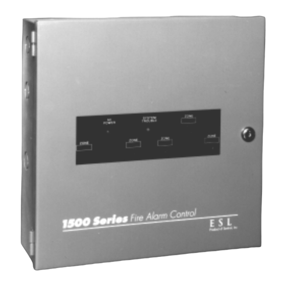
- Page 1 GE Security ESL 1500 Series Fire Alarm Control Panel Installation and Operations Manua...
-
Page 3: Table Of Contents
Table of Contents Precautions and Warnings ................. 1 System Overview ..................1 Panel Listing ........................... 1 Panel Description ..................2 Ordering Information ........................ 2 Installing the Panel ..................3 Optional Zone Expansion and Communicator Module Installation ..........4 Panel Controls ..................... 4 Control Switches ........................ - Page 5 Figures and Tables Figures Figure 1. Internal Panel Configuration ..................3 Figure 2. ZEM or LEM Installation ..................4 Figure 3. Window Label Installation ..................4 Figure 4. Template Diagram ....................6 Figure 5. Class A System Wiring Diagram ................7 Figure 6.
-
Page 6: Precautions And Warnings
The 1500 Series consists of three base models, equipped with one (Model 1501), three (1503), or five (1505) zones. The unique modular design makes it easy and practical to add features such as extra relays, remote annunciators or added fire zones (up to 5). -
Page 7: Panel Description
Class A (Style D) or Class B (Style B) initiating wiring • Reliability of surface-mount design • Superior lightning protection Table 1. Ordering Information Model Title Description 1501 Single zone fire panel 1 initiating circuit, 2 indicating circuits 1503 Three zone fire panel 3 initiating circuits, 2 indicating circuits 1505... -
Page 8: Installing The Panel
Installing the Panel To install the unit, follow these 12 steps, and refer to the proper sections for more information. Create System Diagram: Prepare a carefully laid out drawing of the complete wiring system hookup. Maintain this drawing as a permanent record of the system application and include any future modifications. Note: “As-built”... -
Page 9: Optional Zone Expansion And Communicator Module Installation
Optional Zone Expansion and Communicator Module Installation 24 VAC CASE Z1B+ Z1A+ Z1A– Z1B– FIRE Z1RA– SYSTEM COM NO NC COM GROUND 24VFWR DRILL +15VDC B– AC IN ZONE 1 TROUBLE RELAY ALARM RELAY ZONE TROUBLE SUPERVISORY INDICATING LOW/NO AC POWER A–... -
Page 10: Normal Condition
Optional Remote Notification Disconnect Table 2. Status Indicators Applies to LEM optional module. Disconnects system from remote sites. When activated, the trip circuit fault Indicator Normal Color Description LED and system fault condition will exist and remain until the switch is returned to the normal position. Note: AC Power Green... -
Page 11: System Reset
24 VAC CASE FIRE SYSTEM Z1B+ Z1A+ Z1A– Z1B– Z1RA– COM NO B– GROUND 24VFWR DRILL +15VDC AC IN TROUBLE RELAY ALARM RELAY ZONE ZONE TROUBLE SUPERVISORY INDICATING LOW/NO AC POWER A– LOW/NO BATTERY GROUND FAULT B– SENTROL, INC. INDICATING 1 TROUBLE 12345 SW Leveton Drive Tualatin, Oregon 97062 INDICATING 2 TROUBLE... -
Page 12: Field Wiring
Field Wiring Class A System Wiring Diagram 204-12/24V Power supervision relay Zone 1 is shown with 4-wire detectors, wired in Class A (Style D) 449C Bell circuit 1 is shown with Class A (Style Z) wiring 449C Local Zone 1 alarm (Supervised) Connect to System 15VDC... -
Page 13: Figure 6. Class B System Wiring Diagram
Class B System Wiring Diagram 204-12/24V Power supervision relay 2.7K EOL Zone 1 is shown with 4-wire Resistor detectors, wired in Class B (Style B) 1/2W Bell circuit 1 is shown with Class B (Style Y) wiring 449C 2.7K EOL 541C Resistor 1/2W 449C... -
Page 14: Installation Recommendations/Precautions
Table 3. Wire Resistance ° Gauge Ohms per 1000 ft. @ 20 C of 10 11 12 13 14 15 16 single conductor copper wire ESL 1500 Series Fire Alarm Control Panel 10.0 16.0 Table 4. Alarm Indicating Circuit Wire Size 1. -
Page 15: Field Wiring Checkout Procedures
Do not overlook adequate lightning protection. Lightning damage commonly occurs from three sources: Through alarm loop wiring Through AC power inputs Through earth ground or power ground connections The 1500 System has substantial lightning protection incorporated in all three areas. However, proper lightning protection for AC power must be accomplished where the wire enters the building. -
Page 16: Alarm Indicating Devices
Sprinkler System Waterflow and Supervisory Devices Normally open contact type waterflow alarm devices may be connected, along with conventional manual alarm stations or heat detectors. All zones to which waterflow alarm devices are connected may be programmed so that the system alarm indicating devices cannot be silenced. -
Page 17: Figure 8. Zone Relay Module (Zrm) Wiring Diagram
Zone #1 trouble Supervisory Low/no AC Low/no battery Ground fault Indicating #1 trouble Indicating #2 trouble System+15 VDC of BMB To Z1RA-of BMB COIL (Zone) D6 D1 To Z2RA-of ZEM COIL (Zone 2) To Z3RA-of ZEM (Zone 3) COIL 1. Mounting hole To Z4RA-of ZEM 2. -
Page 18: Connecting Optional Remote Notification Devices
Connecting Optional Remote Notification Devices 1500-RA-5A Note: When using remote annunciators other than the ESL 1500-RA-5A, be sure all circuits have a series resistance of at least 1K ohm. Maximum current should be 15mA per zone. The control unit can properly power one remote annunciator. When a remote annunciator is used, both the BMB and ZEM must be programmed to provide supervision. -
Page 19: Programming
Programming BMB Programming All programming selections are controlled by switches located in the lower right corner of the BMB. Table 5 shows default (factory) prgramming along with a description of each feature. Table 5. BMB Programming Features Switch Factory Feature Description Position 8,7,6... -
Page 20: Testing And System Checkout
Testing and System Checkout Following installation and programming of the unit, a complete test of the entire system must be conducted to assure proper operation. NFPA 72, National Fire Alarm Code should serve as the guide. Follow the recommended procedures, restoring all switches and wiring to normal before proceeding to the next step. -
Page 21: Troubleshooting
Troubleshooting Table 7 provides a quick reference troubleshooting guide that will aide in diagnosing and locating most system faults quickly and efficiently. If you cannot resolve the fault with the assistance of this guide, call Technical Support at 800.648.7424. Table 7. Troubleshooting Guide Trouble indicators Possible cause Corrective action... -
Page 22: Specifications
Battery charge voltage........... 29 V max. Remote Indicator Alarm initiating circuits Voltage ................ 12 VDC Number of circuits..........One - model 1501 Current ..............15 mA max. Three - model 1503 Five - model 1505 1500-LEM - Local Energy Module Type........ -
Page 23: Appendix A, Compatible Equipment
Appendix A, Compatible Equipment The equipment listed here is compatible with the ESL 1500 Series Fire Control Panel. Use ONLY UL Listed compatible quipment with the 1500 Series to assure proper operation. Should you have any questions about compatibility, call technical support at 800.648.7424. -
Page 24: Table 9. Two-Wire Smoke Detector Compatibility
Table 9. Two-Wire Smoke Detector Compatibility Detector Series Detector Models Maximum Line Control Unit Compatibliity Number Resistance Compatibility Identifier per Circuit (Ohms) Identifier ESL 400 Series 429C, 429CT S10A Self-Diagnostic 429CRT, 429CST S11A ESL 500 Series 521B, 521NB DIP SW 1 ON S09A and ESL 500N Series DIP SW 1 OFF S10A 521BXT, 521NBXT... -
Page 25: Appendix B, Standby Battery Power Worksheet
Appendix B ESL 1500 Series Standby Battery Power Worksheet 1500 Series System Standby Current Total Standby Alarm Current Total Alarm Components Per Device Current Per Device Current 1500-BMB (Zone 1) 100 mA 200 mA Indicating Circuit #1 5 mA 1 Amp = 1000 mA Indicating Cicuit #2 5 mA 1 Amp = 1000 mA... -
Page 26: Appendix C, 1500 Series Operating Instructions
Owner’s instruction notices: “Not to be removed by anyone except occupant.’ For Service Contact: _________________________________________________________________________________________________________ _________________________________________________________________________________________________________ _________________________________________________________________________________________________________ ________________________________________________________________________________________________________ GE Security, 12345 SW Leveton Dr., Tualatin, OR 97062 Sales: 800.547.2556 Technical Support: 800.648.7424 Remove this page, frame, and mount adjacent to control unit. ESL 1500 Series Fire Alarm Control Panel... - Page 28 GE Security Tech Support GE Security 800-648-7424 12345 SW Leveton Drive FaxBack: 800-483-2495 Tualatin, OR 97062 12603 Rev. J 04/04 503-692-4052 www.GESecurity.com 64812687 Rev. J USA & Canada: 800-547-2556...
Need help?
Do you have a question about the 1501 and is the answer not in the manual?
Questions and answers