Sign In
Upload
Manuals
Brands
GE Security Manuals
Control Panel
ZP3
User Manuals: GE Security ZP3 Fire Control Panel
Manuals and User Guides for GE Security ZP3 Fire Control Panel. We have
1
GE Security ZP3 Fire Control Panel manual available for free PDF download: Installation & Maintenance Manual
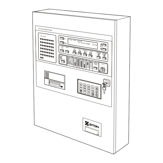
GE Security ZP3 Installation & Maintenance Manual (144 pages)
Fire Control Panel
Brand:
GE Security
| Category:
Control Panel
| Size: 4 MB
Table of Contents
Table of Contents
3
Associated Publications and References
10
List of Abbreviations and Acronyms
10
Table 1: Abbreviations and Acronyms
10
Table 2: Associated Publications and References
10
General Warnings and Precautions
11
Primary Supply
11
Back-Up Battery Supply
12
Regulatory Information
12
Table 3: CPD Certification Information
12
Chapter 1: Installation Overview
13
Introduction
13
Figure 1: ZP3 Fire Control Panel
13
Specification
14
Table 4: ZP3 Fire Control Panel Specification
14
Dimensions
19
Figure 2: ZP3 Fire Control Panel - Dimensions
19
Weight
19
Panel Overview
20
Display and Controls
20
Figure 3: ZP3 Fire Control Panel - Main Features
20
Panel Construction
21
Modular Format
21
Figure 4: ZP3 Fire Control Panel - Modular Construction
21
Internal Features
22
Figure 5: ZP3 Fire Control Panel - Internal Features
22
Main Chassis Assembly
23
Figure 6: ZP3 Fire Control Panel - Main Chassis Assembly
23
Door Assembly
25
Figure 7: ZP3 Fire Control Panel - Door Assembly
25
Internal Wiring
26
Figure 8: ZP3 Fire Control Panel - Internal Wiring
26
Earth Bonding
27
Figure 9: ZP3 Fire Control Panel - Earth Bonding
27
Built-In Communication Port
28
RS232 Built-In Serial Port
28
Figure 10: RS232 Built-In Serial Port
28
Figure 11: Setup - System Configuration Screen
29
Optional Modules
30
Communication Boards
30
Figure 12: ZP3 Fire Control Panel - Communication Boards
30
ZP3AB-RS232 Serial Communications Board (Z-Port 1A)
31
Figure 13: ZP3AB-RS232 Serial Communications Board (Z-Port 1A)
31
Figure 14: Setup - System Configuration Screen
31
ZP3AB-NET1 Network Board (Z-Port 2)
32
Figure 15: ZP3AB-NET1 Network Board (Z-Port 2)
32
Figure 16: Setup - System Configuration Screen
33
ZP3AB-SCB-D Serial Control Bus Driver Board
34
Figure 17: ZP3AB-SCB-D Serial Control Bus Driver Board
34
Accessory Plate
36
Figure 18: ZP3 Fire Control Panel - Accessory Plate
36
Mounting Auxiliary Boards
37
Auxiliary Boards and Modules
37
Figure 19: Mounting Auxiliary Boards
37
Modem
38
Figure 20: ZP3AB-MD3 Modem
38
Figure 21: Installing the Modem Mounting Bracket
39
Figure 22: Installing the Modem
40
Figure 23: Installing the Accessory Plate and Connecting the RS232 and Power Cabling
40
Printer
41
Figure 24: ZP3-PR2 Printer
41
Figure 25: Printer Installation
42
Quick Start
43
Chapter 2: Installing the ZP3 Fire Control Panel
45
Packing/Unpacking
45
Figure 26: ZP3 Panel Packing/Unpacking
45
Figure 27: Removing the Door and Chassis Assembly
46
Removing the Door and Chassis Assembly
46
Figure 28: Storing the Door Assembly
47
Figure 29: Storing the Main Chassis
47
Storing the Door Assembly
47
Storing the Main Chassis
47
Brief Description
48
Preparatory Work
49
Figure 30: Mounting a ZP3 Fire Panel on the Wall
49
Installation Information
50
Cable Entry
50
Figure 31: Cable Entry to the ZP3 Panel
50
Wiring
51
Figure 32: Wiring Practices
51
Surface Mounting
52
Figure 33: Surface Mounting
52
Flush Mounting
53
Figure 34: Flush Mounting
53
Back-Up Batteries
54
Figure 35: Back-Up Batteries Mounting Position
54
Figure 36: Securing the Back-Up Batteries
54
Good Practice
55
Earth Connections
55
Screen Connections
55
Separation of Wiring
55
Good Connections
55
Careful Handling of Electronics
55
Cleanliness
55
Neatness
55
Chapter 3: Field Wiring
57
Terminal Layout
57
Figure 37: ZP3 Fire Control Panel Main Board Terminal Layout
57
Power Supply
58
Mains Supply
58
Figure 38: Mains Power Supply Connection
58
Auxiliary 24 VDC Supply
59
External Power for Accessory Boards
59
Figure 39: Auxiliary 24 VDC Supply
59
Figure 40: Powering Optional Accessory Boards from a Separate External Power Supply
60
Figure 41: Monitoring External Power
60
Monitoring External Power
60
Battery Connection
61
Connection Overview
61
Figure 42: Battery Connection
61
Power Supply and Battery Calculations
62
Table 5: ZP3 System Load Calculation
62
Battery Calculation
63
Power Supply Load Calculation
63
Table 6: Power Supply Load Calculation
63
Table 7: Battery Calculation
63
Z-Loop
64
Z-Loop Wiring
64
Loop Isolators
64
Figure 43: Z-Loop Wiring
64
Z-Loop Parameters
65
Screening
65
Cable Sizing
65
Table 8: Screen Connection Wiring Best Practice
65
Common Outputs
66
Common Sounder Outputs
66
Figure 44: Common Sounder Outputs Wiring
66
Common Fire / Fault Outputs
67
Figure 45: Common Fire/Fault Outputs
67
Remote Manned Centre Outputs
68
Figure 46: Remote Manned Centre Outputs
68
Auxiliary Boards
69
ZP3AB-RL8 Relay Board
69
Figure 47: ZP3AB-RL8 Relay Board
69
ZP3AB-MA8 Monitored Output Board
70
Figure 48: ZP3AB-MA8 Monitored Output Board
70
ZP3AB-OP24 Transistor Output Board
71
Figure 49: ZP3AB-OP24 Transistor Output Board
71
ZP3AB-MIP8 Input Board
72
Figure 50: ZP3AB-MIP8 Input Board
72
Chapter 4: Software Programming
73
Introduction
73
Setup Menu
74
Menu Operation
74
The Keypad
74
Figure 51: Keypad
74
Table 9: Keypad Description
74
Setup Menu
75
Figure 52: Main Menu
75
Figure 53: Setup Menu
75
Programming Menus
76
Figure 54: Programming Menu Examples
76
Menu Structure
77
Figure 55: Menu Structure (Sheet 1 of 3)
77
Figure 56: Menu Structure (Sheet 2 of 3)
78
Figure 57: Menu Structure (Sheet 3 of 3)
79
Menu Functions
80
Zoning
80
Title Message Edit
80
Watchdog Counters
80
Table 10: Zoning Options
80
I/O Mapping
81
Table 11: I/O Mapping Options
81
Points: Individual Setting: View
82
Table 12: Individual Point Settings View Options
82
Points: Individual Settings: Edit
83
Points: Global Settings: View
83
Table 13: Individual Point Settings Edit Options
83
Table 14: Point Addresses View Options
83
Points: Global Settings: Editing
84
Points: Accept Points
84
Sounders
84
Table 15: Point Addresses Edit Options
84
Table 16: Sounder Setup Options
84
Paradigm
85
System Configuration: Panel Options
85
Table 17: Paradigm Sensor Setup Options
85
Table 18: Panel Configuration Options
85
System Configuration: Control Key Levels
86
System Configuration: Peripheral Comms
86
Table 19: Function Access Level Options
86
Table 20: System Configuration - Peripheral Comms Options
86
System Configuration: Relays
87
System Configuration: Printer
87
Table 21: System Configuration Relay Setup Options
87
Table 22: System Configuration Printer Setup Options
87
System Configuration: [Various]
88
Table 23: Various System Configuration Setup Options
88
Planner
89
Level 4 Operations
89
Table 24: Planner Setup Options
89
Table 25: Level 4 Operation Setup Options
89
Chapter 5: System Configuration
91
System Specification
91
General Information
91
Input-Output Mapping
91
Panel Identification
91
Menu Access Codes
91
Control Key Access Levels
91
Local Programming
91
Networking
91
Zone Allocation
92
Zone Identification Messages
92
Point Information
92
Device Identification Message
92
Detector Self-Test
92
Sounder Bases
92
Loop Sounders
92
Panel Sounders
93
Z-Loop Isolators
93
Common Relays
93
Printer
93
Alarm Time Display
93
Silence Delay
93
Cause and Effect Functions
94
Input-Output Mapping
94
Output Parameters
94
Input Parameters
94
Point Address Structure
95
Auxiliary Board Addresses
95
System Address List
96
System Bus Addresses
96
User Bus Addresses
100
EN54 Setup Requirements
101
Summary
101
Chapter 6: System Commissioning
103
Introduction
103
Verification
103
Verify System Design
103
Verify Equipment Installation
103
Verify Wiring
103
Remove Lithium Time/Date Batteries Protective Tab
104
Verify System Programming
104
Figure 58: Lithium Time/Date Batteries Protective Tab
104
System Tests
105
Panel Check
105
Z-Loop Wiring Check
105
Table 26: Device Reference Values
105
Z-Loop Wiring Parameters
106
Z-Loop Functional Tests
106
Data Wiring RS485
106
Chapter 7: Peer-To-Peer 3 Protocol
107
Introduction
107
New Data Structure
107
Compatibility with Maestro and Planner
107
Peer-To-Peer 3 (P2P3) Protocol
107
Overview
107
Compatibility with Older Versions of Panel Software
107
P2P3 New Features
108
Panel Comms Enable/Disable
108
Interpanel Support for Remote Diagnostics Across the Network
108
Remote Diagnostics To/From Planner (ZCP3 Protocol on RS232 Port)
108
Panel Filters Set, Store and Send Capability
108
New Network Filters
109
Filter Description
109
Fetch Disables Control
109
Disable Events
109
General Status Events
109
Use of Network Communications Filters
109
Overview
109
Fetch Disables Control
110
Disable Events
110
Language Loading
110
Appendix A: ZP Wiring Guide
111
Introduction
111
General
111
Panel Power Supply Connections
111
Earth Connection
112
Figure 59: Typical Panel Earth Connection
112
Remote Equipment Earth
113
System Cabling
113
Overview
113
Circuit Types
113
Circuit Schematic
114
Figure 60: Typical Single Panel System
114
Figure 61: Typical Multi-Panel System
114
Z-Address Lines
115
Function
115
Features
115
Wiring Styles
115
Style a
115
Figure 62: Style a - Address Line Wiring
115
Style B
116
Style C
116
Figure 63: Style B - Address Line Wiring
116
Figure 64: Style C - Address Line Wiring
116
Line Isolators
117
Operation
117
Schematic
117
Rules for Using Line Isolators
117
Figure 65: Line Isolator Usage Schematic
117
Shielding
118
Rules for Using Shielded Cable
118
Shielding Technique
118
Figure 66: Shielded Cable
119
Figure 67: MICC
119
Unshielded Cable
120
Rules for Using Unshielded Cable
120
Loop Length
120
Cable Size
121
Serial Communication Lines
121
General
121
RS232 Ports
121
Rules for RS232 Cabling
121
RS485 Ports
121
Table 27: Loop Length Cable Size (Various Diameters) - Assuming no High Power Devices
121
Rules for RS485 Cabling
122
DC Control Lines
122
General
122
DC Cable Type
122
DC Cable Size
122
Table 28: DC Cable Size
122
Appendix B: ZP3 System Maintenance
123
Overview
123
Record Keeping
123
System Specification
123
Routine Maintenance
123
Quarterly (Three-Monthly) Maintenance
123
Table 29: ZP3 Fire Control Panel - Quarterly Checks
123
Annual Maintenance
125
Table 30: ZP3 Fire Control Panel - Annual Checks
125
Maintenance Menu
126
Introduction
126
Menu Access
126
Figure 68: Keypad
126
Table 31: Keypad Description
126
Maintenance
127
Figure 69: Main Menu
127
Figure 70: Maintenance Menu
127
Menu Structure
128
Figure 71: Maintenance Menu Structure
128
Menu Functions
129
Edit Disabled
129
View Disabled
129
Enable All
130
Reports to Display
130
Reports to Printer
130
Calibrate Detectors
131
Test
131
Comms Enable/Disable
131
Figure 72: Maintenance: Comms Enable/Disable
131
Interpretation of Analogue Readings
133
Introduction
133
Table 32: Device Definition Table and Device Type Analogues Interpretation
134
Table 33: Analogue Status - Idle Limits
136
Table 34: Analogue Status - Alarm Values
137
Table 35: Extinguishing Control Unit - Slot 5 (Address 1)
138
Table 36: Extinguishing Control Unit - Slot 6 (Address 1)
138
Corrective Maintenance
139
Removing and Replacing the Lithium Time/Date Batteries
139
Fuses and Indicators
139
Figure 73: Removing the Lithium Time/Date Batteries
139
Figure 74: Fuses and Indicators
140
Removing and Replacing the Back-Up Batteries
141
Figure 75: Removing the Back-Up Batteries
141
Advertisement
Advertisement
Related Products
GE Security 1200C
GE Security 1500-2.7
GE Security 1500-BMB
GE Security 1500-LEM
GE Security 1500-RA-5A
GE Security 1500-SH
GE Security 1500-TK
GE Security 1500-TR
GE Security 1500-ZEM
GE Security 1500-ZRM-5
GE Security Categories
Security System
Security Camera
DVR
Control Panel
Smoke Alarm
More GE Security Manuals
Login
Sign In
OR
Sign in with Facebook
Sign in with Google
Upload manual
Upload from disk
Upload from URL