Table of Contents
Advertisement
Quick Links
User Instructions, Installation, maintenance fo r
• I N D U C T I O N C O O K E R S •
cod. I/301/??
Pro fe ssio na l
Professional
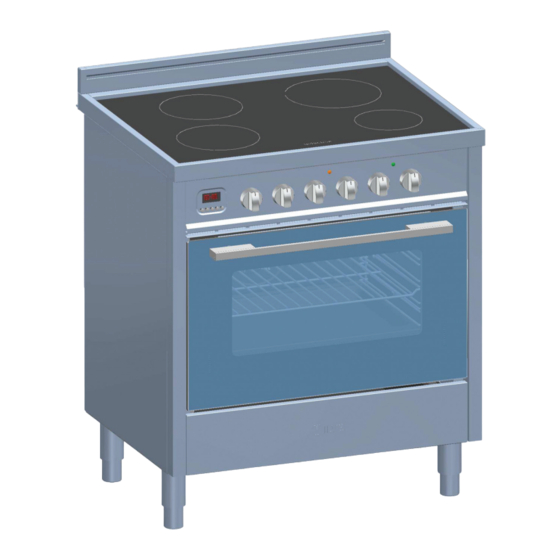
Cookers characteristics
Dimension (inch)
Width
29 7/8"
Height
33 15/32" - 35 53/64"
Depth
23 5/8"
Model UP... I76
Electrical characteristics
Voltage
Frequency
Power
120/240V
60Hz
11.1KW
04/2012
Advertisement
Table of Contents

Related Manuals for ILVE UP… I76


Summary of Contents for ILVE UP… I76
- Page 1 User Instructions, Installation, maintenance fo r • I N D U C T I O N C O O K E R S • Pro fe ssio na l Professional Cookers characteristics Model UP… I76 Dimension (inch) Electrical characteristics Width Voltage 29 7/8”...
- Page 2 IMPORTANT - PLEASE READ AND FOLLOW • Before beginning, please read these instructions completely and carefully. • Do not remove permanently affi xed labels, warnings, or plates from the product. This may void the warranty. • Please observe all local and national codes and ordinances. •...
- Page 3 Keeping appliance area clear and free from combustible materials, gasoline and other fl ammable vapors and liquids. I M P O R T A N T I N S T R U C T I O N • Proper Installation – Be sure your appliance is properly installed and grounded by aqualifi ed technician. •...
- Page 4 • Do not insert any piece of paper, cardboard, cloth, etc. between the pan and the heating area, as this might initiate a fi re. • As metallic objects are heated up very quickly when placed on the operating heating area, do not place any other objects (closed cans, aluminium foil, cutlery, jewelry, watches etc.) on the induction cooker.
-
Page 5: Installation Instructions
I N S T A L L A T I O N I N S T R U C T I O N S This appliance shall only be installed by an authorized person. This appliance shall be installed in accordance with the manufactures installation instructions. -
Page 6: B A S E F E E T
B A S E F E E T Legs are packed in carton box. Legs should be installed near to where the appliance is to be used, as they are not secure for long transit. After unpacking the range, raise it about a foot to remove the bottom shipping skid. Keep the unit raised to permit legs to be screwed into our couplings and lower it gently to keep any undue strain from the legs and internal mounting hardware. -
Page 7: Anti-Tip Stability Device Installation Instructions
ANTI-TIP STABILITY DEVICE INSTALLATION INSTRUCTIONS 1. The anti-tip bracket have to be attached to rear wall, as show in F i g . 3, before backguard installation. The dimension for the bracket location from the fl oor have to be determined after range legs have been adjusted to the proper installation height as show in the installation instructions and the range has been levelled. -
Page 8: O V E N C L E A N I N G A N D C A R E
O V E N C L E A N I N G A N D C A R E It is advised to clean the oven after each use. The dirt comes off more easily, preventing it from being burnt repeatedly at high temperatures. - Page 9 Self-cleaning panels If the oven is equipped with self-cleaning catalytic panels, at normal cooking temperatures (430°F) the catalytic enamel favours the transformation of splashes of fat into a light powder residue. This powder may be removed with a damp cloth once the oven has cooled.
- Page 10 U S E R M A N U A L I M P O RTA N T: keep children away from the appliance when it operates. The oven door becomes very hot. Safety rules do not always cover any type of accident. The appliance must not be used for heating purposes. If other electric appliances are connected to outlets placed near the appliance, make sure that the connection cables will not be trapped in the oven door while operating.
-
Page 11: Induction Principle
COOKTOP BEFORE THE FIRST USE Clean your hob with a damp cloth, and then dry the surface thoroughly. Do not use detergent which risks causing blue- tinted colour on the glass surface. INDUCTION PRINCIPLE An induction coil is located under each heating zone. When it is engaged, it produces a variable electromagnetic fi eld which produces inductive currents in the ferromagnetic bottom plate of the pan. - Page 12 I NST R U CTI O NS FOR USE IMPORTANT The ceramic hob remains hot for a long time after use. Do not touch the hob with your hands or let children near it. The residual heat indicator will remain lit until the hob has cooled down. If any cracks appear in the ceramic hot, disconnect the appliance immediately from the mains and call an authorized technical service centre.
-
Page 13: Controls Description
CON TR OL S DES CR IP TION H1-4 Hob heating element knob Multifunction electric oven selector Electric oven thermostat Indicating electric oven selection Fan failure light Thermostat WARNING If the ST light is on, the appliance is malfunctioning. Turn off and disconnect from power supply. -
Page 14: Booster Function
BOOSTER FUNCTION The purpose of the booster function is to give more power to a determined area in order to reduce the necessary cooking time. This function is activated by push and turning the knob clockwise from position 0 (off) to the fi nal position ( * fi g. 13). The symbol [P] appears on the display, meaning that the booster function is activated. -
Page 15: Cleaning And Maintenance
LIMIT OF THE DURATION OF OPERATION A maximum time of continuous operation is associated with each cooking area. This depends on the set power level. If the limit of the duration of operation is reached, the respective area is switched off OPERATING TABLE (purely indicative values) Knob Type of cooking... -
Page 16: Us E Of The Ele C Tronic Pr Ogram Mer
US E OF THE ELE C TRONIC PR OGRAM MER R E M A R K : To know what the electronic programmer drive see ELECTRONIC PROGRAMMER TABLE (at the end of the booklet). AT T E N T I O N : D O N OT U S E E L E C T RO N I C P RO G R A M M E R W H E N V E N T I L AT E D G A S F U N C T I O N I S S E L E C T. 1. -
Page 17: Minute Minder
8. SEMI-AUTOMAT IC FUNCTION WITH END OF COOKING TIME Choose the function end of cooking ( button) and set the fi nal time with the +/- buttons. The symbols “A” and the pot symbol appear. The oven is switched on. When the time coincides with the set time the oven is switched off and the pot symbol disappears. - Page 18 US E OF THE MU LT IF U NCTIO N O VEN Turn the selector knob (S) and choose the function. Select the desired temperature from 100˚F to 500˚F turning the thermostat (T). If your oven is fi tted with a programmer then you have to switch it on. Oven light To switch on the oven light, press the switch (S).
-
Page 19: Fan O Ven Co Oking Chart
FAN O VEN CO OKING CHART MEAT S T EMPERATURE [°F] POSITION TIME [min] Roast beef 340 - 360 2 – 3 40 - 50 Roast ox 340 – 370 2 – 3 40 – 60 Roast veal 320 – 360 2 –... - Page 20 NATU RA L CO NV EC TION OVEN COOK ING CHA RT MEAT S T EMPERATURE [°F] POSITION TIME [min] Roast beef 2 – 3 60 - 80 Roast ox 450-500 2 – 3 50 – 60 Roast veal 2 – 3 60 - 80 Roast lamb 40 –...
- Page 21 ELE CTR IC A L S KE TCH E S KEYS KEYS BLACK OVEN LAMP BROWN OVEN LAMP TERMINAL BOARD WHITE ELECTRICAL IGNITION MICROSWITCH YELLOW GRILL MICROSWITCH YELLOW-GREEN ROTISSERIE GREY DOOR MICROSWITCH BLUE NEUTRAL ELECTRICAL IGNITION TRASFORMER MINUTE COUNTER/PROGRAMMER MINUTE COUNTER/CLOCK ELECTRONIC CONTROLLER OVEN VALVE INDUCTION ZONE...
- Page 24 Phone: 450-963-1303 / 1-888-651-2534 Fax: 450-963-8985 email: info@aginternational.ca COOKERS • OVENS • HOB-COOKERS INDUSTRIA LAVORAZIONE VENETA ELETTRODOMESTICI S.p.A. Via Antoniana, 100 35011 Campodarsego (PD) - Italy Tel. +39 (049) 9200990 - Fax +39 (049) 9201010 mail@ilve .com - www.ilve .com...
Need help?
Do you have a question about the UP… I76 and is the answer not in the manual?
Questions and answers