
Summary of Contents for Synaccess netBooter Series
- Page 1 User’s Manual Synaccess User's Manual For netBooter™ Series NP-02, NP-08, NP16 and NPB-20 Part # 1140 May 2007 Synaccess Networks, Inc. (760) 930 – 0473 Synaccess Networks, Inc. www.synaccess-net.com Page 1 of 46...
- Page 2 User’s Manual Copyright Notice Copyright © 2007 by Synaccess Networks, Inc. The material discussed in this manual is the proprietary property of Synaccess Networks, Inc. AII retains all rights to reproduction and distribution of this document. FCC Warning The Federal Communications Commission has set limits for emitted radio interference. The Synaccess Networks systems are constructed with this electromagnetic interference (EMI) limitation in mind.
-
Page 3: Table Of Contents
TATUS WITH A APPENDIX A WARRANTY INFORMATION ......................43 ............................43 IMITED ARRANTY APPENDIX B SERIAL CONSOLE PORT INTERFACES..................45 APPENDIX C RS-232 TO RJ45 CONVERSION CABLES..................46 (760) 930 – 0473 Synaccess Networks, Inc. www.synaccess-net.com Page 3 of 46... - Page 4 Figure 32 - User Account Management Menu (Terminal) ................. 40 Figure 33 - User Account Management Menu (Web Page) ................ 41 Figure 34 – Viewing and Changing System Operation Status ..............42 (760) 930 – 0473 Synaccess Networks, Inc. www.synaccess-net.com Page 4 of 46...
-
Page 5: System Description
Local Master Port access: offers data rates from 2400 to 115200 bits/second and optional hardware handshaking (CTS/RTS). There are two operation modes for the port: Console Transparent Mode and System Control Mode. (760) 930 – 0473 Synaccess Networks, Inc. www.synaccess-net.com Page 5 of 46... -
Page 6: What You Can Do With The System
AC draw from a system is crossed predefined threshold. Remote control anywhere by emailing. Via emails, you are able to manage the systems or user communication equipment power sources when LAN access is impossible. Via emails, (760) 930 – 0473 Synaccess Networks, Inc. www.synaccess-net.com Page 6 of 46... -
Page 7: Figure 2 - Illustration Of Typical Application
Scheduling AC outlet power cycling periodically or per weekly planner. Each outlet can be programmed with it’s own timer. Figure 2 - Illustration of Typical Application (760) 930 – 0473 Synaccess Networks, Inc. www.synaccess-net.com Page 7 of 46... -
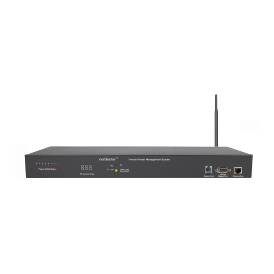
Page 8: Front And Back Panel
User’s Manual 1.3 Front and Back Panel: Figure 3 - NP-08 Front and Back Panel Illustration NP-02 Front and Back Panel Illustration Figure 4 - (760) 930 – 0473 Synaccess Networks, Inc. www.synaccess-net.com Page 8 of 46... -
Page 9: Figure 5 - Np-10 Front And Side Panel Illustration
5. Factory Default Reset switch: Allow a user to reset the system to factory default settings. The switch is located behind the small front panel opening. 6. Power Outlet sockets: (760) 930 – 0473 Synaccess Networks, Inc. www.synaccess-net.com Page 9 of 46... - Page 10 10. Audio Alarm Off Switch: To temporarily turn off the audio alarm when aggregated AC current draw crosses over the defined threshold. This control switch is equipped on NPB-20 system. (760) 930 – 0473 Synaccess Networks, Inc. www.synaccess-net.com Page 10 of 46...
-
Page 11: Important Safety Precautions For Hardware Installation
Insert the new replacement to the holder with “+” facing up. CAUTION: Risk of Explosion if Battery is replaced by an Incorrect Type. Dispose of Used Batteries According to the Instructions. (760) 930 – 0473 Synaccess Networks, Inc. www.synaccess-net.com Page 11 of 46... -
Page 12: Access To The System
If you do not see the screen as shown in the Figure 6, it is likely that the system is not in the default state. Otherwise, your connection to the Local Master port is established. ************************************************************ * Synaccess Networks Inc., Carlsbad, CA, USA. Copyright(c) * System NP-08 ************************************************************ HW:3.1 SW:4.1.1... -
Page 13: User Privileges And Port Reservations
With this access method, an RS232 port on an external Modem device is connected to the Local Master Port. Typically, a Modem device is equipped with a DCE (Data Communication Equipment) (760) 930 – 0473 Synaccess Networks, Inc. www.synaccess-net.com Page 13 of 46... -
Page 14: Telnet Access
To terminate an active Telnet session, use the command “logout” at the terminal. If you are at a serial port terminal and notice that the terminal is disabled because it is taken over by a (760) 930 – 0473 Synaccess Networks, Inc. www.synaccess-net.com Page 14 of 46... -
Page 15: Web Access
You must have an account on the system in order to access the system via this method. Without a valid account, you are only able to view the following web page and get a copy of the Help text message. (760) 930 – 0473 Synaccess Networks, Inc. www.synaccess-net.com Page 15 of 46... -
Page 16: Email Access
NP system controlling commands. The NP system periodically checks incoming mails from a designated POP mail server. The system sends a reply (760) 930 – 0473 Synaccess Networks, Inc. www.synaccess-net.com Page 16 of 46... -
Page 17: Snmp Information
NP systems. Open the TCP/IP Network Configuration Menu and then click the button “Get SNMP MIB File” to download the MIB file that is stored in the system’s memory. (760) 930 – 0473 Synaccess Networks, Inc. www.synaccess-net.com Page 17 of 46... - Page 18 (or power cord). temperatureThreshold .3.1.1.7 Environment temperature threshold in F. temperatureReading .3.1.1.8 Temperature reading in F. Value is zero when the temperature probe is not installed. (760) 930 – 0473 Synaccess Networks, Inc. www.synaccess-net.com Page 18 of 46...
-
Page 19: Autoping And Power Reboot
NP system lost network connection. To change the default gateway IP address as ping destination, use TCP/IP Configuration Menu to enter your desired destination address. (760) 930 – 0473 Synaccess Networks, Inc. www.synaccess-net.com Page 19 of 46... -
Page 20: Using Control Command
Administration level, you are able to operate any serial ports and power outlets, reserve or unreserved any ports or outlets even if they are reserved by other users. See Section 2.2 for a complete description of user privileges. (760) 930 – 0473 Synaccess Networks, Inc. www.synaccess-net.com Page 20 of 46... -
Page 21: Figure 13 - Control Command Help Menu
Repeats previous command ***Note - if Restricted Access Mode is on, non-Admin users are limited to use commands marked with "*" > Figure 13 - Control Command Help Menu (760) 930 – 0473 Synaccess Networks, Inc. www.synaccess-net.com Page 21 of 46... -
Page 22: Using Configuration Menu
If you already have accounts established and want to start configuring the system or to change serial console port and power outlet operation status, choose this menu option. (760) 930 – 0473 Synaccess Networks, Inc. www.synaccess-net.com Page 22 of 46... -
Page 23: System Main Menu
6) Setup New or Existing Accounts 7) Reload Factory Defaults 8) Save Settings 9) Quit >Please enter your selection Figure 15 - System Main Menu (Terminal Program Screen) (760) 930 – 0473 Synaccess Networks, Inc. www.synaccess-net.com Page 23 of 46... -
Page 24: Figure 16 - System Main Menu (Web Page)
Helpful info: control command “nwshow” displays network connectivity information.. Option 4 - Configure Serial Console Port: Enters Serial Console Port Configuration submenu. Helpful info: control command “sshow” displays all serial console port settings.. (760) 930 – 0473 Synaccess Networks, Inc. www.synaccess-net.com Page 24 of 46... -
Page 25: System Access Setup Menu
Save. q) Quit. ***Note for 6): for controlling non-Admin user's access to system data. >Please enter your selection: Figure 17 - System Access Setup Menu (Terminal Screen) (760) 930 – 0473 Synaccess Networks, Inc. www.synaccess-net.com Page 25 of 46... -
Page 26: Figure 18 - System Access Control Menu (Web Page)
Enable or disable web access to the system. Default to enable. Telnet Access: Enable or disable Telnet access to the system. Default to enable. Only one active Telnet session is permissible. (760) 930 – 0473 Synaccess Networks, Inc. www.synaccess-net.com Page 26 of 46... - Page 27 Enable or disable Email alarm sending method. Alarm Notification Interval (Minute): Define alarm notification sending interval. Save and Quit: Save current configuration data and return to previous configuration menu. (760) 930 – 0473 Synaccess Networks, Inc. www.synaccess-net.com Page 27 of 46...
-
Page 28: Tcp/Ip Network Configuration Menu
A static IP Address is an IP address that never changes. This IP address will be used if a DHCP server IP has no IP offered or DHCP automatic IP address is disabled. (760) 930 – 0473 Synaccess Networks, Inc. www.synaccess-net.com Page 28 of 46... -
Page 29: Figure 20 - Tcp/Ip Network Configuration Menu (Web Page)
(reply) Emails. “mail.synaccess-net.com” and “smtp.tom.com” are examples of SMTP Email servers. NP supports SMTP log on secure password authentication option. Helpful Info: use the command “emailget” to immediately check incoming emails. Incoming Email Account Name: (760) 930 – 0473 Synaccess Networks, Inc. www.synaccess-net.com Page 29 of 46... -
Page 30: More About Emailing Access
“&” is a command delimiter; “SystemName” is a user defined system or device name; “username” and “password” are valid user account name and password; and “command” is the actual system control command. (760) 930 – 0473 Synaccess Networks, Inc. www.synaccess-net.com Page 30 of 46... -
Page 31: Figure 21 - Sending A Control Command "Rb 2" From "Hotmail" Web Page
Before a command is executed, a confirmation reply email is sent. The destination of the replying email address is already defined in the Network Configuration Table. Figure 22 shows a reply email is received and displayed at “hotmail” web site. (760) 930 – 0473 Synaccess Networks, Inc. www.synaccess-net.com Page 31 of 46... -
Page 32: Figure 22 - Reply Email Before A Control Command Is Executed
If this happens, a reply email is sent to indicate the problem of the command, as shown in the Figure 23. Figure 23 – Reply Email Indicating System Name Mismatch Error Helpful Info: (760) 930 – 0473 Synaccess Networks, Inc. www.synaccess-net.com Page 32 of 46... -
Page 33: Serial Console Port Configuration Menu
3) Stop bits(1 or 2)......1 4) Parity(1-Even,2-Odd,3-None)....3 5) Flow control(1-hardware,2-None)....2 6) Port name........Master 7) Save: 8) Quit: >Please select a parameter to change: – Serial Port Parameter Entry Table Figure 24 (760) 930 – 0473 Synaccess Networks, Inc. www.synaccess-net.com Page 33 of 46... -
Page 34: Figure 25 - Serial Port Setup Menu (Web Page)
Flow Control is hardware handshaking using CTS/RTS signals on the connectors. Please see Appendix A for information about RS232 connector pin assignments. Port Name: Assign a name for the port. Always assigned to the name “Master”. (760) 930 – 0473 Synaccess Networks, Inc. www.synaccess-net.com Page 34 of 46... -
Page 35: Power Outlet Setup Menu
The default value is 5 seconds. This is parameter applies to all power outlets. List of All Power Port Status: Display all power ports current statuses, as shown in Figure 30. (760) 930 – 0473 Synaccess Networks, Inc. www.synaccess-net.com Page 35 of 46... -
Page 36: Figure - 27 List Of Power Outlet Status (Terminal Screen)
Undefined | On | Open | >***Power reboot duration: 5 seconds. > >Press key "Enter" to continue ... Figure - 27 List of Power Outlet Status (Terminal Screen) (760) 930 – 0473 Synaccess Networks, Inc. www.synaccess-net.com Page 36 of 46... -
Page 37: Figure 28 - Power Outlet Setup Menu (Web Page)
10)Timer Toggle Duration ......5 11) Help 12) Save: 13) Quit: >Please select a parameter to change: Figure 30 - Power Outlet Parameter Menu (Timer On Mode) Power Outlet Name: (760) 930 – 0473 Synaccess Networks, Inc. www.synaccess-net.com Page 37 of 46... - Page 38 Enter an IP address of the probed communication equipment IP. This IP address is associated to the power outlet. Timer Period Timer Start Time Loop Count 3 Loop Count 4 Loop Count 2 Loop Count 1 Toggle Duration (760) 930 – 0473 Synaccess Networks, Inc. www.synaccess-net.com Page 38 of 46...
-
Page 39: Figure 31 - Definitions Of Timer Parameters
2) Toggle Power Outlets for 300 times: Toggling Power outlet on/off state 300 times in a period of 10 seconds starts immediately. Current Calendar date and time are: Aug. 10 , 10:00 am. (760) 930 – 0473 Synaccess Networks, Inc. www.synaccess-net.com Page 39 of 46... -
Page 40: User Account Management Menu
3) List all user names 4) Change login name and password 5) Lock power outlet 6) Unlock power outlet 7) Quit Figure 32 - User Account Management Menu (Terminal) (760) 930 – 0473 Synaccess Networks, Inc. www.synaccess-net.com Page 40 of 46... -
Page 41: Viewing And Changing Operation Status With A Web Page
Change power outlet on/off status by clicking “on/off” push switch button icon. Reboot a power outlet by clicking “Reboot” push switch button icon. Get current all ports status by pressing “Refresh View” button. (760) 930 – 0473 Synaccess Networks, Inc. www.synaccess-net.com Page 41 of 46... -
Page 42: Figure 34 - Viewing And Changing System Operation Status
User’s Manual Figure 34 – Viewing and Changing System Operation Status (760) 930 – 0473 Synaccess Networks, Inc. www.synaccess-net.com Page 42 of 46... -
Page 43: Appendix A Warranty Information
Appendix A Warranty Information Two-Year Limited Warranty Synaccess Networks, Inc. ("Synaccess") warrants to the original End User ("Purchaser") that this computer product purchased from Synaccess or an authorized Synaccess dealer (“Product”) is free from manufacturing defects in material and workmanship for the applicable warranty period as set forth in the Product specification, from the date of shipment to Synaccess authorized dealer. - Page 44 Some states do not allow the exclusion or limitation of incidental or consequential damages, so the above limitation or exclusion may not apply to you. (760) 930 – 0473 Synaccess Networks, Inc. www.synaccess-net.com Page 44 of 46...
-
Page 45: Appendix B Serial Console Port Interfaces
When hardware flow control is enabled, this Send signal is raised by the Local Master Port when it is ready to receive new data from an external device. Open Open (760) 930 – 0473 Synaccess Networks, Inc. www.synaccess-net.com Page 45 of 46... -
Page 46: Appendix C Rs-232 To Rj45 Conversion Cables
Pin No. Signal RS-232 — RJ45 (8-pin) C-RJ45-DB9M-4, RJ-45 to RS232 (Male, DTE) cable, 4’. RS-232 — DB9 Male RJ45 (8-pin) DB-9 M Pin No. Signal Pin No. Signal (760) 930 – 0473 Synaccess Networks, Inc. www.synaccess-net.com Page 46 of 46...
Need help?
Do you have a question about the netBooter Series and is the answer not in the manual?
Questions and answers