
Related Manuals for Scopus IRD-2900 Series


Summary of Contents for Scopus IRD-2900 Series
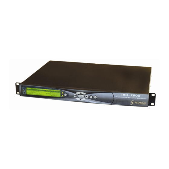
- Page 1 IRD-2900 Series Professional Integrated Receiver Decoders ANUAL 100793) COPUS OCUMENTS . 4.6/ SW 1.80/ D 2007) ECEMBER...
- Page 3 IRD-2900 Series Professional Integrated Receiver Decoders IRD-2900 Series Professional Integrated Receiver Decoders ANUAL 100793) COPUS OCUMENTS . 4.6/ SW 1.80/ D 2007) ECEMBER...
- Page 5 2005 Scopus Video Networks Ltd. All rights reserved. Scopus Video Networks Ltd. Reserves the rights to alter the equipment specifications and descriptions in this publication without prior notice. No part of this publication shall be deemed to be part of any contract or warranty unless specifically incorporated by reference into such contract or warranty.
- Page 6 Page ii (Rev. 4.6/ SW v1.80/ December 2007)
- Page 7 Professional Integrated Receiver Decoders INTRODUCTION Scopus Video Networks Ltd. takes great pride in delivery of its products and makes every endeavor to ensure its clients full satisfaction. On behalf of the whole Scopus team, we would like to extend our congratulations on your investment in the IRD-2900 Series of Professional Integrated Receiver Decoders.
-
Page 8: T Echnical S Upport
Scopus Video Networks Support will assign the number; this must • accompany the item being returned and is referred to in all correspondence. Send the item to Scopus Video Networks with the number included in the • accompanying documentation (shipping and customs forms). - Page 9 (6) months from date of repair or until the end of original warranty period, whichever is the later date. SCOPUS Video Networks Ltd. sole liability under this warranty shall be limited to the repair or replacement with equivalent units at SCOPUS Video Networks Ltd. facilities, of any product or parts thereof that do not conform to SCOPUS Video Networks Ltd.
-
Page 10: Fcc Warning
OTICE Scopus Trade Name Integrated Receiver Decoder Product Name IRD-2900 Series Product Model Number These devices comply with Part 15 of the FCC Rules. PERATION IS SUBJECT TO THE FOLLOWING TWO CONDITIONS These devices do not cause harmful interference. •... - Page 11 OLICY As part of its commitment to comply with global environmental initiatives, Scopus will continue to actively work with its supply chain to ensure the ongoing compliance with EU directives as well as the procurement and utilization of reliable, environmentally responsible alternatives to hazardous substances.
-
Page 12: Table Of Contents
User Manual Overview TABLE OF CONTENTS Chapter 1. Overview............1-1 1.1. General Information............1-1 1.2. Highlights and Benefits............1-2 1.3. Applications ..............1-3 1.4. Functionality ..............1-4 1.5. Mechanical Structure ............1-5 1.5.1. Front Panel ..............1-5 1.5.2. Various Front-Ends ............1-6 1.5.3. - Page 13 A.2.2 PC Serial-COM (Terminal) Software........A-7 A.2.3 Opening Hyperterminal from MS Windows ......A-7 A.2.4 Defining the Communication ..........A-8 A.2.5 Checking PC Terminal Communication with the IRD .... A-10 A.2.6 Installation: ..............A-11 Scopus Documents (p/n 100793) Page vii...
- Page 14 User Manual Overview Appendix B IP-Front End Software Upgrade Procedure ..B-1 Appendix C Aspect Ratio Configuration Process....C-1 General ................C-1 Aspect Ratio Conversion Machine........C-1 Table of Conversions............C-3 Appendix D Configuration File...........D-1 Introduction..............D-1 Parameters ..............D-1 D.2.1 Stream Configurations ............
- Page 15 Figure 1-14: IRD-2991 Rear Panel ............1-15 Figure 1-15: IRD-2992 Rear Panel ............1-16 Figure 2-1: Pair of Scopus Rack Slides ........... 2-4 Figure 2-2: Scopus Rack Slide Measurement Specifications....... 2-5 Figure 2-3: Laying the Device on the Rack-Slides ........2-6 Figure 2-4: Clipped Mounting Brackets...........
- Page 16 User Manual Overview Figure 3-11: Select-Value Parameter ............3-16 Figure 3-12: Refresh Button ..............3-17 Figure 3-13: IP Address Field ..............3-18 Figure 3-14: IRD-2900 Web Management Access Box.......3-19 Figure 4-1: Web Interface Preset Screen..........4-2 Figure 4-2: Web Interface Preset Recall Tab ..........4-4 Figure 4-3: Web Interface Save Preset Screen .........4-5 Figure 4-4:...
- Page 17 Figure A-10: Port Settings Tab.............. A-10 Figure A-11: HyperTerminal Window............A-11 Figure A-12: Update Software Version Command ........A-12 Figure A-13: Erasing Flash Process ............A-13 Figure A-14: Ready to Receive New Software ......... A-14 Scopus Documents (p/n 100793) Page xi...
- Page 18 (jackscrew)................F-14 Abbildung 1-12: Gleichstrom-Energieversorgung und Gestellmontage-Erdungsschraubenwinde (Jackscrew) ................. F-15 Image G-1: Paire de Rack Slides de Scopus ........... G-3 Figure G-2: Spécifications de dimensions des rack-slides de Scopus... G-4 Figure G-3: poser l’appareil sur les Rack-Slides ........G-5 Figure G-4: Crochets d’assemblage attachés ...........
- Page 19 RS-232 données a faible vitesse et GPI Pin-Out ....G-11 Tableau G-4: RS-422 Données de vitesse élevée Pin-Out ......G-12 Tableau G-5: Pin-Out cable à fibre optique Audio 3-4 (Scopus P/N 204346) G-12 Tableau G-6: AES/EBU pin-out de câbles à fibres optiques équilibrés (Scopus P/N 204345) ................G-12 Tableau G-7: IRD-2900 vérification de fonctionnement ......
-
Page 21: Overview
ASI transport-stream input • SNMP and web based management support • The IRD-2900 Series concurrently decodes up to two video programs from the transport stream. The IRD-2900 Series features the following product lines: IRD-296x - Professional single 4:2:0 decoder IRD •... -
Page 22: Highlights And Benefits
1.2. IGHLIGHTS AND ENEFITS The processing platform’s main features and options include: MPEG2 4:2:0/4:2:2 decoder • H.264 4:2:0 field upgradeable using Scopus-Neotion module • Variety of front-end options including DVB-S, DVB-S2, DVB-DSNG, G.703, • MPEG-over-IP and DS3-ATM DVB-S2 professional •... -
Page 23: Applications
Satellite distribution • Telco distribution • DSNG • Syndication • Scopus offers this series of professional IRDs in a wide range of standard configurations, with the flexibility to select specific interfaces and applicable required features. Scopus Documents (p/n 100793) Page 1-3... -
Page 24: Functionality
User Manual Overview 1.4. UNCTIONALITY The TS Router block receives input streams from an available source, for example: L-Band, MPEG-over-IP IN and ASI IN. Then the block routes the selected input to the Master and Slave decoders. Each decoder decodes one program from the input stream, routed by the TS router block, and provides decoded digital audio and video streams. -
Page 25: Mechanical Structure
LCD. The four-way touch pad allows parameter modification and scrolling through the embedded VBI menus. Two LEDs show the WARNING and PWR/FAIL status (see Figure 1-3). Figure 1-3: Front View of the IRD Scopus Documents (p/n 100793) Page 1-5... -
Page 26: Various Front-Ends
User Manual Overview 1.5.2. Various Front-Ends IRD-2900 supports the following interfaces: DVB-S Single L-Band input • DVB-S Dual L-Band input • DVB-DSNG Dual L-Band input • DVB-S2 Dual L-Band input • MPEG over IP (MPEGoIP) dual input • G.703 E3 single input with Loop-through •... -
Page 27: Software Permission (Licensing)
After unit ordering - order the relevant features. In this case, a 16 • character key issued by Scopus video networks will be provided. The key must be entered to the unit thru the front-panel or the web- interface. For details see section 4.2.11.6 When RS-232 low-speed-data and/or RS-422 high-speed-data are enabled the PID Filtering is unavailable. -
Page 28: Ird-2900 Models
RS-232 low speed data output • • quality (lower connector) RS-422 high speed data output • 2 active analog – audio - stereo • H.264 (Scopus-Neotion module) • balanced interfaces DVB-S2 Advance Modulation • • (optional) OTES The IRD-2960 does not support the Decoder Only configuration. -
Page 29: Figure 1-8: Ird-2961 Rear Panel
In the case of power failure or system shutdown, ASI OUT 1 output will become ASI loop-through. Use ASI OUT 1 output for cascading a chain of IRD-2900. The Russian SECAM D/K (composite video only) is available only through special orders. Scopus Documents (p/n 100793) Page 1-9... -
Page 30: Figure 1-9: Ird-2962 Rear Panel
• • unbalanced interfaces H.264 (One Program Only) • SNMP management (10/100 Base-T) RS-232 low speed data output • • Web-based management (10/100 H.264 (Scopus-Neotion module) • • Base-T) DVB-S2 Advance Modulation • (optional) • Front panel A/V monitoring •... -
Page 31: Figure 1-10: Ird-2963 Rear Panel
This model requires a breakout cable to connect to the AES/EBU interfaces. In case of power failure or system shutdown, ASI OUT 1 output will become ASI loop-through. Use ASI OUT 1 output for cascading a chain of IRD-2900 Scopus Documents (p/n 100793) Page 1-11... -
Page 32: Figure 1-11: Ird-2980 Rear Panel
User Manual Overview 1.5.4.5. IRD-2980 Interfaces and Features The IRD-2980 is a single 4:2:0/4:2:2 decoder. The IRD-298x family consists of two composite video interfaces. Both CVBS #1 and CVBS #2 connectors are for broadcast quality video. Figure 1-11 illustrates the IRD-2980 rear panel. The IRD-2980 basic and software-licensed features are also detailed. -
Page 33: Figure 1-12: Ird-2981 Rear Panel
Base-T) downmixing. Pro MPEG FEC • • Front panel A/V monitoring PID and service filtering • • connectors H.264 (One Program Only) • RS-232 low speed data output • DVB-S2 Advance Modulation • (optional) Scopus Documents (p/n 100793) Page 1-13... -
Page 34: Figure 1-13: Ird-2990 Rear Panel
User Manual Overview OTES This model requires a breakout cable to connect to the AES/EBU interfaces and to connect to the 3rd and 4th analog stereo pairs. In the case of power failure or system shutdown, ASI OUT 1 output will become ASI loop-through. -
Page 35: Figure 1-14: Ird-2991 Rear Panel
Pro MPEG FEC • SNMP management (10/100 H.264 (One program only) • • Base-T) PID and service filtering • Web-based management (10/100 RS-232 low speed data output • • Base-T) DVB-S2 Advance Modulation • (optional) • Scopus Documents (p/n 100793) Page 1-15... -
Page 36: Figure 1-15: Ird-2992 Rear Panel
User Manual Overview OTES This model requires a breakout cable to connect to the 3rd and 4th analog stereo pairs. In case of power failure or system shutdown, ASI OUT 1 output will become ASI loop-through. Use ASI OUT 1 output for cascading a chain of IRD-2900. 1.5.4.9. -
Page 37: Management
The IRD-2900 can be controlled and configured from a standard PC terminal (over Ethernet). The terminal provides access to control and monitor functionalities that are not available when using any IRD-2900 front panel feature. Scopus Documents (p/n 100793) Page 1-17... -
Page 38: Characteristics And Specifications
User Manual Overview 1.7. HARACTERISTICS AND PECIFICATIONS following section provides with IRD-2900 Characteristics specification. 1.7.1. Transport Stream Interface Options EATURE PECIFICATIONS DVB-S Interface - F-type 75Ω • INGLE NPUT Constellation - QPSK • Single L-band input • Frequency range - 950-2150 MHz •... - Page 39 • 2 L-Band RF 75Ω inputs with LNB control • Modulation Scheme Recovery: Automatic (ACM • mode) Physical Layer Scrambling support • Multiple input transport stream (MSI) support using • Input Stream Identifier (ISI) Scopus Documents (p/n 100793) Page 1-19...
- Page 40 User Manual Overview EATURE PECIFICATIONS MPEG IP I NPUT Two physical links - 10/100 Base-T, RJ-45 – one • active at a time Two logical sources (sockets) – one active at a time • Physical Link and logical source redundancy •...
-
Page 41: Advanced Processing
PCR re-stamping • VBR and CBR modes (NULL stuffing) • Forward only and filter only modes • Dynamic Service filtering (tracks PIDs' • modifications) Static PID filtering • PSI/SI tables are not modified. • Scopus Documents (p/n 100793) Page 1-21... -
Page 42: Decoder Outputs
User Manual Overview EATURE PECIFICATIONS High speed data: RS-422 Up to 20 Mbps, RJ-45 • (supported by IRD-2960, IRD-2990) IP Data Out (RJ-45): up to 60Mbps (MPE de- • capsulation) 1.7.3. Decoder Outputs EATURE PECIFICATIONS IDEO Video Formats: • PAL-B/G/I/M/N/D, NTSC, SECAM L/B/G/K1 •... - Page 43 IRD-2900 Series Professional Integrated Receiver Decoders EATURE PECIFICATIONS H.264 Based on Scopus-Neotion CAM module Video Characteristics: Video decoding standard: H.264 part 10 • Profile: Full D1 Main Profile up to Level 3.0 (one • 4:2:0 service) Video Format: PAL & NTSC •...
- Page 44 User Manual Overview EATURE PECIFICATIONS UDIO Modes: stereo, joint stereo, dual channel, single • channel Analog max output level: +18 dBu @ 600Ω • Digital max output level: 0 dBFs • Attenuation control at -64 dB to 0 dB and mute •...
-
Page 45: Conditional Access
2 GPI dry contacts for various status and fault • indications NHANCED Front panel display: signal quality, Eb/N0, BER, • ONITORING ASI format, network and service information, CA information, CI slots, video and audio decoded information Scopus Documents (p/n 100793) Page 1-25... -
Page 46: Compliance
User Manual Overview EMOTE SNMP management • Web-based management • Telnet • Terminal via RS-232 or RS-485 • Software download • VER THE Software download • 1.7.6. Compliance EATURE PECIFICATIONS EN55013 (CISPR 13) • EN55020 (CISPR 20) • EN55022 (CISPR 22) •... -
Page 47: Physical And Power Specifications
Dimensions (HxWxD) – • 1RU X 19” X 14”/44mm X 482.6mm X 357mm Weight – 3.5Kg. (7.7lbs). • OWER Voltage: • • 100 - 240V AC, 50/60Hz • Power consumption – up to 50w max Scopus Documents (p/n 100793) Page 1-27... -
Page 49: Installation
Do not move or ship equipment unless it is correctly packaged in its original • wrapping and shipping containers. Only Scopus trained personnel can perform service and maintenance. • To prevent lightning damage, ground the unit according to local regulations. -
Page 50: Site Preparation
User Manual Installation ORTH MERICAN power connection, select a power supply cord that is UL Listed and CSA Certified 3 - conductor, [18 AWG], terminated in a molded on plug cap rated 125 V, [15 A], with a minimum length of 1.5m [six feet] but no longer than 4.5m...For European connection,... -
Page 51: Mechanical Rack Installation
ONLY AFTER THE UNIT IS SWITCHED OFF AND UNPLUGGED. 2.3.2. Mechanical Rack Installation Due to its considerable weight, the device must be placed on a pair of rack- slides, specially designed for Scopus products (see Figure 2-1). AUTION ’ HE RACK... -
Page 52: Figure 2-1: Pair Of Scopus Rack Slides
User Manual Installation Figure 2-1: Pair of Scopus Rack Slides Slide structure is especially designed to ensure proper ventilation of Scopus products, as it is consistent with the ventilation scheme of all Scopus rack- mount devices. AUTION SING RACK SLIDES THAT ARE NOT SPECIALLY DESIGNED FOR... -
Page 53: Figure 2-2: Scopus Rack Slide Measurement Specifications
IRD-2900 Series Professional Integrated Receiver Decoders Figure 2-2 illustrates the exact measurements of Scopus’ special rack-slides. Figure 2-2: Scopus Rack Slide Measurement Specifications Fasten the pair of rack slides to the rack’s side rails in the device’s designated location with four M6 screws (two on each side of the rack) before continuing. -
Page 54: Figure 2-3: Laying The Device On The Rack-Slides
User Manual Installation Figure 2-3: Laying the Device on the Rack-Slides 2. The device is supplied with two mounting brackets (see Figure 2-4). The mounting brackets are clipped to the device chassis on both sides before leaving the factory. Align the mounting brackets’ holes with the relevant holes in the rack’s side rails. -
Page 55: Figure 2-5: Device Mounted On A Pair Of Rack-Slides
Figure 2-5: Device Mounted on a Pair of Rack-Slides A single pair of rack-slides can carry up to 50Kg (110 lbs). This allows saving rack space by placing a number of Scopus rack-mount devices one upon the other (be careful not to exceed the specified maximum weight). -
Page 56: Figure 2-6: Multiple Devices Mounted On A Single Pair Of Rack-Slides
User Manual Installation Figure 2-6 illustrates multiple devices when rack-mounted on a single pair of rack-slides. Figure 2-6: Multiple Devices Mounted on a Single Pair of Rack-Slides Page 2-8 (Rev. 4.6/ SW v1.80/ December 2007) -
Page 57: Insertion Of The Dvb-Ci Module (Pcmcia)
Figure 2-7: DVB-CI Module three following conditions are valid: The installed card must be EN50221 • compatible Services have been selected at TV1/TV2 (for • further information see section 4.2.5.1) Using a valid card licensing • Scopus Documents (p/n 100793) Page 2-9... -
Page 58: Cable Connection
User Manual Installation 2.4. ABLE ONNECTION The IRD-2900 provides all the connections on its rear panel. The rear panel is comprised of audio outputs, video outputs, data outputs, and control interfaces (see Table 2-1 for cable connection specifications). Figure illustrates the IRD-2992 rear panel in order show connector types. Figure 2-8: IRD-2992 Rear Panel Table 2-1: IRD-2900 Rear Panel –... -
Page 59: Figure 2-9: 9-Pin Male Connector Pin Numbering
RG11 A/U (recommended) SDI out 1 &2 75 Ω BNC RG-59 The IRD-2900 series supports terminal-control from a standard PC through a serial RS-232/RS-485 connector. Figure 2-9 illustrates the Control Interface and Low Speed Data/GPI 9-pin male connectors pin numbering. - Page 60 User Manual Installation Table 2-2 lists the RS-232/RS-485 Control Interface connector pin-out. Table 2-2: RS-232/RS-485 Control Connector Pin-Out UNCTION UNCTION RS-232 CD/RS-485 TX (+) RS-232 DSR/RS-485 TX (-) RS-232 RxD RS-232 RTS RS-232 TxD RS-232 CTS/RS-485 RX (+) RS-232 DTR RS-232 Ring/RS-485 RX (-) Common Table 2-3 lists the RS-232 low speed data and GPI interface pin-out.
- Page 61 IRD-2900 Series Professional Integrated Receiver Decoders Table 2-5 lists the Audio 3-4 breakout cable interface pin-out. Table 2-5: Audio 3-4 Breakout Cable Pin-Out (Scopus P/N 204346) UNCTION UNCTION Audio 4 XLR Right (+) Audio 4 XLR Left Common Audio 4 XLR Left (+)
-
Page 62: Initialization And Configuration
User Manual Installation 2.5. NITIALIZATION ONFIGURATION Before powering-up the IRD-2900, ensure that all cabling is correct. Ensure that the unit is connected to the main power supply and correctly grounded. 2.5.1. Electrical Power Connection The IRD-2900 is powered by an AC power supply unit or by an optional external DC power source. - Page 63 When the IRD is rack-mounted, the jackscrew (see Figure 2-11) must be connected to the rack housing, which in turn should be properly grounded. GND Contact + Contact - Contact Grounding Jackscrew Figure 2-11: DC Power Supply and Rack-Mount Grounding Jackscrew Scopus Documents (p/n 100793) Page 2-15...
-
Page 64: Powering Up
User Manual Installation 2.5.2. Powering Up When powering up the IRD-2900 and the receiver is not tuned, expect one of the following warnings: Front-End warning – Demodulator not sync • Bit Stream warning – No sync – 0x47 detected • Bit Stream warning –... -
Page 65: Performing Serviceability Check
On the LCD display, the LCD status message reads "STATUS OK". On the IRD-2900 front panel the two LEDs are lit green. The service selected is displayed on the LCD display. Video picture is displayed on monitor. Audio channels left and right. Scopus Documents (p/n 100793) Page 2-17... -
Page 67: Ird-2900 Control Interfaces
The IRD-2900 front panel contains: LCD Display • The LCD display is a large, easy to use, graphical display. It is used to display enhanced menus with graphical interfaces, such as: charts, radio buttons, tables, and icons. Scopus Documents (p/n 100793) Page 3-1... - Page 68 User Manual IRD-2900 Control Interfaces Status LEDs • The two LEDs indicate WARNING and PWR/FAIL statuses, when both LEDs are lit green the IRD-2900 status is OK. The WARNING LED (Green/Orange) indicates the operational status. The PWR/FAIL LED (Green/Red) indicates the hardware status.
-
Page 69: Ird-2900 Front Panel Screen Types
4 4 4 4 Audio Audio Audio Audio 5 5 5 5 Data Data Data Data 6 6 6 6 Conditional Access Conditional Access Conditional Access Conditional Access 7 7 7 7 Unit Unit Unit Unit Scopus Documents (p/n 100793) Page 3-3... - Page 70 User Manual IRD-2900 Control Interfaces A. Top line indicates the menu name (Configuration) and the menu hierarchal 1 1 1 1 - - - - 2 2 2 2 Configuration Configuration Configuration Configuration Root Root Root Root position ( , for example under the menu).
- Page 71 Press [ESC] to abort the selection and return to the Edit Menu screen without changing the parameters. Press [Enter] to select the currently enabled button The selected option becomes enabled and the former active option is disabled. Scopus Documents (p/n 100793) Page 3-5...
- Page 72 User Manual IRD-2900 Control Interfaces 3.1.2.4. Edit Value Screen The Edit Value screen enables setting a parameter value. The parameter value can be a number or a string of characters. Each digit or character is set up individually. In this example, the Edit Value screen displays the following information: Pcr1 Pcr1 Pcr1...
- Page 73 Press [Enter] to select the marked option (the selected option is enabled the former enabled option is disabled ). The display returns up one level to the Select Value screen; the new option is displayed as the current parameter option. Scopus Documents (p/n 100793) Page 3-7...
-
Page 74: Ird-2900 Menu Tree
User Manual IRD-2900 Control Interfaces 3.1.3. IRD-2900 Menu Tree Setup, control, and monitoring of the IRD-2900 operation can be performed locally by using the IRD-2900 Menu. This menu is displayed on the front panel LCD display and is operated using the front panel control keys. -
Page 75: Front Panel Initialization Sequence
Front-End Warning – The warning LED turns orange (For details see • Appendix E). ___________________________________________ ___________________________________________ ___________________________________________ ___________________________________________ Service1: Service1: Service1: Service1: Click Enter for menu Click Enter for menu Click Enter for menu Click Enter for menu ___________________________________________ ___________________________________________ ___________________________________________ ___________________________________________ Scopus Documents (p/n 100793) Page 3-9... - Page 76 User Manual IRD-2900 Control Interfaces 3. Click [Enter] to activate and enter the IRD-2900 Root Menu: Root Root Root Root 1 1 1 1 Preset Preset Preset Preset 1 1 1 1 Configuration Configuration Configuration Configuration 2 2 2 2 Status Status Status...
-
Page 77: Figure 3-3: Web-Based Management Window - General View
(see Figure 3-3 for general view example). Figure 3-3: Web-Based Management Window – General View The web-based management is best viewed by Internet Explorer 6.0. Scopus cannot guarantee viewing quality in older IE versions or other web-browsers, such as FireFox, Opera, and so on. -
Page 78: Controls And Displays
User Manual IRD-2900 Control Interfaces The section is divided into the following groups: Control and Displays – Details the web-management screen sections and • their control elements (see Section 3.2.1) Initializing the Web-Based Management – Details the initialization • procedure of the Web- management control interface (see Section 3.2.2) 3.2.1. -
Page 79: Figure 3-5: Web-Based Management Title
The following paragraphs detail the different sections: ITLE A static title to the web-based management, displays the Scopus logo and the device's type (IRD-2900, see Figure 3-5). Figure 3-5: Web-Based Management Title ENU AND The tabs surround the explorer window section (see the following paragraph). -
Page 80: Figure 3-6: Web-Based Management Menu And Sub-Menu Tabs
User Manual IRD-2900 Control Interfaces Figure 3-6: Web-Based Management Menu and Sub-Menu Tabs TATUS The Status menu, located under the 'Status' tab, displays a read-only table. The table details information regarding the various services encoded by the unit (see Figure 3-7. For detailed information about the Status menu, see Section 4.3). -
Page 81: Figure 3-8: Main-Menu Tabs
Audio 1 or Audio 2 configuration menus. The sub-menu tabs are aligned above the explorer-window section. A selected sub-menu tab changes its color from light-blue to darker-blue (see Figure 3-9). Figure 3-9: Sub-Menu Tabs Scopus Documents (p/n 100793) Page 3-15... -
Page 82: Figure 3-10: Edit-Value Parameter
User Manual IRD-2900 Control Interfaces ALUE ARAMETER The parameters-sections in the explorer window display lists of editable parameters, available for user-configuration. The edit-value parameters provides a free-text field for the user to type the required value (from within a given range). -
Page 83: Initializing The Web-Based Management
• Set the Default Gateway • In order to avoid any errors and faults, Scopus recommends all Ethernet configurations to be preformed through the front-panel or the RS323 only A. To set the IP Address: 1. Access the IP Address edit screen. To access the screen, from the Root... -
Page 84: Figure 3-13: Ip Address Field
1. Launch the web browser. The web-based management is supported and can be operated through most web browsers. However, Scopus recommends Internet Explorer 5.0 and higher for optimal operation. 2. Enter the IRD-2900 IP Address in the Address field, in the following format: http://xxx.xxx.xxx.xxx... -
Page 85: Figure 3-14: Ird-2900 Web Management Access Box
Professional Integrated Receiver Decoders Figure 3-14: IRD-2900 Web Management Access Box Once the initialization is complete and the web-management is displayed, the user can set up the system. For details on the web-management operation, see Chapter 4. Scopus Documents (p/n 100793) Page 3-19... -
Page 87: Operation And Management
Save Current 2 2 2 2 Rename Rename Rename Rename 3 3 3 3 Delete Delete Delete Delete 4 4 4 4 Delete All Delete All Delete All Delete All 5 5 5 5 Scopus Documents (p/n 100793) Page 4-1... -
Page 88: Figure 4-1: Web Interface Preset Screen
User Manual Operation and Management To access the Preset menu through the web-interface from the management bar, click on the Preset tab. The following figure shows the web-interface Preset menu: Figure 4-1: Web Interface Preset Screen The Preset menu consists of the following five submenus: Recall –... -
Page 89: Recall Preset
This screen shows the selected preset name at its title and the option Recall. 3. Select the RECALL submenu tab. When selecting a preset, the front panel's orange warning light might lit until the unit is synced with the new setup applied. Scopus Documents (p/n 100793) Page 4-3... -
Page 90: Save Current Preset
User Manual Operation and Management To recall a preset through the web-interface: 1. From the management bar, click the Preset tab. 2. Click Recall tab. Figure 4-2 shows the Recall tab: Figure 4-2: Web Interface Preset Recall Tab 3. Open the Recall drop-down menu. From the list select a preset to recall. 4.1.2. -
Page 91: Figure 4-3: Web Interface Save Preset Screen
Figure 4-3: Web Interface Save Preset Screen Save Current menu includes two options: Overwrite Existing –For details see section 4.1.2.1. • New Name- –For details see section 4.1.2.2. • Scopus recommends storing the default manufacture's setup as a preset. Scopus Documents (p/n 100793) Page 4-5... - Page 92 User Manual Operation and Management 4.1.2.1. Overwrite an Existing Preset The Overwrite Existing option allows saving the unit's current setup over a stored one. To overwrite an existing preset through the front panel: 1. Access the Overwrite Existing screen. From the front panel go to Root Preset Save Current Overwrite Existing.
-
Page 93: Figure 4-4: Web Interface Save Tab
[RIGHT] keys. To save, press [ENTER]. To name a new preset through the web-interface: 1. From the management bar, click on the Preset tab. 2. Click on Save tab. Figure 4-5 shows the New Name section: Scopus Documents (p/n 100793) Page 4-7... -
Page 94: Rename Preset
User Manual Operation and Management Figure 4-5: Web Interface – Save Preset As New Name Tab 3. Type a name for the preset in the New-Name textbox. 4. Press [ENTER] to finish. 4.1.3. Rename Preset The Rename submenu allows editing a stored preset name. To rename a preset through the front panel: 1. -
Page 95: Figure 4-6: Web Interface Rename Preset Screen
Figure 4-7: Web Interface – Rename Preset Tab 3. Open the Existing Configuration drop-down menu. From the list select a preset to rename. 4. Type a new name for the preset in the New-Name textbox. Scopus Documents (p/n 100793) Page 4-9... -
Page 96: Delete Preset
User Manual Operation and Management 4.1.4. Delete Preset The Delete submenu allows removing stored preset. To delete a preset through the front panel: 1. Access the Delete screen. From the front panel go to Root Preset Save Current Delete. The following screen appears, lists all stored presets and allows selecting a preset to delete. -
Page 97: Figure 4-8: Web Interface Delete Preset Screen
Figure 4-8: Web Interface Delete Preset Screen 2. Click on Delete tab. Figure 4-9 shows the Delete tab: Figure 4-9: Web Interface – Delete Preset Tab 3. Open the Delete drop-down menu. From the list select a preset to delete. Scopus Documents (p/n 100793) Page 4-11... -
Page 98: Delete All Presets
User Manual Operation and Management 4.1.5. Delete All Presets The Delete All submenu allows removing all stored preset. To delete all presets through the front panel: 1. Access the Delete screen. From the front panel go to Root Preset Save Current Delete All. -
Page 99: Configuration
Data Data Data Data 6 6 6 6 Conditional Access Conditional Access Conditional Access Conditional Access 7 7 7 7 Unit Unit Unit Unit 8 8 8 8 Figure 4-10: IRD-2900 Configuration Main Menu Scopus Documents (p/n 100793) Page 4-13... -
Page 100: Receiver Modules
User Manual Operation and Management The IRD-2900 can support either IP or L-Band receiver modules. The configuration menu structure changes according to each of these available module options. 4.2.1. Receiver Modules The purpose of the receiver module is to single out a selected Transport Stream from the transmission that reaches the IRD-2900 inputs, to demodulate it, and pass on the digital transport stream to the decoder module. -
Page 101: Satellite Receiver Modules
Frequency Scan Frequency Scan 1 1 1 1 0 0 0 0 DVBS DVBS- - - - MCLK DVBS DVBS MCLK MCLK MCLK 1 1 1 1 1 1 1 1 135[MHz] 135[MHz] 135[MHz] 135[MHz] Scopus Documents (p/n 100793) Page 4-15... -
Page 102: Figure 4-11: Dvb-S Receiver Parameters Menu Screen
User Manual Operation and Management Figure 4-11 displays the corresponding DVB-S Receiver Parameters menu (Web Management screen). Figure 4-11: DVB-S Receiver Parameters Menu Screen The DVB-S Receiver Configuration parameters are detailed in the following paragraphs: Page 4-16 (Rev. 4.6/ SW v1.80/ December 2007) - Page 103 <01.000000 - - - - 45.000000> <01.000000 45.000000> <01.000000 <01.000000 45.000000> 45.000000> Available values range from 01.000000 to 45.000000 Mbaud. It is important to input the accurate Symbol Rate down to the sixth digit after the decimal point. Scopus Documents (p/n 100793) Page 4-17...
- Page 104 User Manual Operation and Management FEC R The FEC Rate parameter sets the Forward error correction rate value. The FEC parameter can be acquired from the satellite transponder information or can be set to automatic. When in Automatic mode, the IRD-2900 device tries all FEC rates until locking the rate to the transport stream.
- Page 105 IRDs using the loop-through connector on the L-Band interface or when this voltage is supplied to the LNB by external source. 13V (VERTICAL) – Vertical polarization • 18V (HORIZONTAL) – Horizontal polarization • Scopus Documents (p/n 100793) Page 4-19...
- Page 106 User Manual Operation and Management LNB 22 KH The receiver controls the LNB band by sending a 22 kHz signal. When the signal is sent, the LNB uses its High Band Local Oscillator (L.O.). When the signal is not sent, the LNB uses its Low Band L.O. The local oscillator is used to convert the signal from Ku-Band or C-Band to L- Band.
- Page 107 • C-BAND – Defines C-Band LNB L.O. type • DiSEqC (9.75, 10.75) • When selecting the Ku-Band or the C-Band, you must manually set the L.O. frequency (see the following Section in this chapter). Scopus Documents (p/n 100793) Page 4-21...
- Page 108 User Manual Operation and Management REQUENCY ANGE The Frequency Range parameter defines the input frequency in the Ku, C or L bands. This parameter affects the displayed frequencies and ranges of the IRD-2900 DVB-S receiver parameters. The following figure illustrates the Frequency Range screen.
- Page 109 DVBS MCLK MCLK 135[MHz] 135[MHz] 135[MHz] 135[MHz] 1 1 1 1 100[MHz] 100[MHz] 100[MHz] 100[MHz] 2 2 2 2 The available frequencies are: 135[MHz] – This option is set by defaults. • 100[MHz} • Scopus Documents (p/n 100793) Page 4-23...
- Page 110 User Manual Operation and Management 4.2.2.2. DVB-S2 Receiver Configuration This section details the front panel menus that enable configuring the DVB-S2 receiver in an IRD-2900 DVB-S2 front end device. The following is a screen of the DVB-S2 Receiver configuration menu as displayed on the front panel screen: Receiver Receiver...
-
Page 111: Figure 4-12: Dvb-S2 Receiver Parameters Menu Screen
The following figure illustrates the Frequency screen. Frequency Frequency Frequency Frequency [GHz] [GHz] [GHz] [GHz] <0.950000 - - - - 2.150000> <0.950000 2.150000> <0.950000 <0.950000 2.150000> 2.150000> The displayed frequency range corresponds with the frequency band that is currently selected. Scopus Documents (p/n 100793) Page 4-25... - Page 112 User Manual Operation and Management Table 4-2 lists the different bands, and their respective frequency ranges. Table 4-2: Band Frequency Designations REQUENCY 0.950000-2.150000GHz L-Band 3.200000-4.200000GHz C-Band 10.700000-12.750000GHz Ku-Band YMBOL The Symbol Rate menu is used for adjusting the receiver’s symbol rate to the symbol rate of the received signal.
- Page 113 Set the Roll-Off factor in accordance with the transmitted Roll-Off factor. The following figure illustrates the Roll-Off screen. Roll Roll- - - - off Roll Roll 1 1 1 1 2 2 2 2 3 3 3 3 Scopus Documents (p/n 100793) Page 4-27...
- Page 114 User Manual Operation and Management Available options for the Roll-off factor are: • • • ILOTS In order to expedite carrier recovery, the standard allows two operating modes for each modulation type: Pilot-less (i.e. no Pilot symbols are inserted) and Piloted, where Pilot symbols are inserted to aid carrier synchronization.
- Page 115 Spectral Inversion screen. Spectral Inversion Spectral Inversion Spectral Inversion Spectral Inversion AUTOMATIC AUTOMATIC AUTOMATIC AUTOMATIC 1 1 1 1 INVERTED INVERTED INVERTED INVERTED 2 2 2 2 NORMAL NORMAL NORMAL NORMAL 3 3 3 3 Scopus Documents (p/n 100793) Page 4-29...
- Page 116 User Manual Operation and Management The available options are: AUTOMATIC – the IRD-2900 automatically detects and sets the Spectral • Inversion Mode INVERTED – sets the IRD-2900 receiver to “inverted” Spectral Inversion • Mode. NORMAL - sets the IRD-2900 receiver to normal Spectral Inversion Mode. •...
- Page 117 Turning on the Freq Drift Compensation in the following menu activates the automatic frequency adjustment. When Drift compensation is turned off, the device uses the original frequency setting that was inserted by the operator. Scopus Documents (p/n 100793) Page 4-31...
- Page 118 User Manual Operation and Management The following figure illustrates the Freq Drift Compensation screen. Freq Drift Compensation Freq Drift Compensation Freq Drift Compensation Freq Drift Compensation 1 1 1 1 2 2 2 2 The available options are: OFF – Drift Compensation is off; the receiver remains tuned to the •...
- Page 119 Frequency Band Scan Frequency Band Scan Frequency Band Scan 1 1 1 1 2 2 2 2 The available options are: OFF – band scan is disabled • ON – starts the band scan • Scopus Documents (p/n 100793) Page 4-33...
- Page 120 User Manual Operation and Management DVBS-MCLK The DVBS-MCLK screen allows setting the DVBS Main Clock frequency. The following figure illustrates the DVBS-MCLK screen. DVBS DVBS- - - - MCLK MCLK DVBS DVBS MCLK MCLK 135[MHz] 135[MHz] 135[MHz] 135[MHz] 1 1 1 1 100[MHz] 100[MH 100[MH...
- Page 121 12 Frequ 12 Frequ ency Range ency Range ency Range L BAND L BAND L BAND L BAND 13 Frequency Band Scan 13 Frequency Band Scan 13 Frequency Band Scan 13 Frequency Band Scan Scopus Documents (p/n 100793) Page 4-35...
-
Page 122: Figure 4-13: Dvb-Dsng Receiver Parameters Menu Screen
User Manual Operation and Management Figure 4-13 displays the corresponding DVB-DSNG receiver parameters menu (Web Management screen). Figure 4-13: DVB-DSNG Receiver Parameters Menu Screen REQUENCY The Frequency parameter must be set in accordance with the required satellite transponder frequency. The frequency can be acquired from the satellite transponder information. - Page 123 2 2 2 2 DVBS- - - - 8PSK DVBS 8PSK DVBS DVBS 8PSK 8PSK 3 3 3 3 DSNG- - - - 16QAM DSNG 16QAM DSNG DSNG 16QAM 16QAM 4 4 4 4 Scopus Documents (p/n 100793) Page 4-37...
- Page 124 User Manual Operation and Management The Roll-off menu is used for setting the receiver’s roll-off factor value according to the roll-off factor of the transmitted signal. The Roll-off factor is the factor that is used for the base-band shaping of the transmitted signal.
- Page 125 LNB Power Supply LNB Power Supply 13V (VERTICAL) 13V (VERTICAL) 13V (VERTICAL) 13V (VERTICAL) 1 1 1 1 18V (HORIZONTAL) 18V (HORIZONTAL) 18V (HORIZONTAL) 18V (HORIZONTAL) 2 2 2 2 3 3 3 3 Scopus Documents (p/n 100793) Page 4-39...
- Page 126 User Manual Operation and Management The available options are: OFF – No voltage is supplied to the LNB. Use this option either when • cascading IRDs using the loop-through connector on the L-Band interface or when this voltage is supplied to the LNB by external source. 13V (Vertical) –...
- Page 127 2 2 2 2 The available options are: OFF – Drift Compensation is off; the receiver remains with the configured • frequency. ON - Drift Compensation is on; the receiver adjusts its optimal frequency. • Scopus Documents (p/n 100793) Page 4-41...
- Page 128 User Manual Operation and Management 4.2.2.4. DVB-ATM Module This section details the front panel menus that enable configuring the DVB-ATM receiver in an IRD-2900 DVB-ATM front end device. The following is the DVB-ATM Receiver Configuration menu as displayed on the IRD-2900 front panel screen: 1 1 1 1 - - - - 2 2 2 2 - - - - 1 1 1 1 General General...
- Page 129 The FEC parameter allows the user to enable or disable FEC for the ATM receiver. The following is the front panel FEC screen: VPI Address Address Address Address 1 1 1 1 Enable Enable Enable Enable 2 2 2 2 Disable Disable Disable Disable Scopus Documents (p/n 100793) Page 4-43...
- Page 130 User Manual Operation and Management 4.2.2.5. IP Receiver Configuration Menu This section details the front panel menus that enable configuring the IP receiver in an IRD-2900 IP front end device. The following is the IP Receiver configuration menu as it is displayed on the IRD- 2900 front panel screen: Receiver Receiver...
-
Page 131: Figure 4-14: Dvb-Ip Receiver - Mpegoip 1 Parameters Menu Screen
Logical Source (Socket) – for configuring the IP parameters of the TS • source end-device (“logical port” parameters) FEC – for configuring the Forward Error Correction parametersThe three • options are detailed follows. The three options are detailed as follows: Scopus Documents (p/n 100793) Page 4-45... - Page 132 User Manual Operation and Management HYSICAL The physical Link menu is used for enabling the operation of the physical link (the MPEGoIP IN1 interface in this example), as well as for configuring its parameters. Physical Physical Link Link Physical Physical Link Link 1 1 1 1 - - - - 2 2 2 2 - - - - 1 1 1 1 - - - - 1 1 1 1 - - - - 1 1 1 1...
- Page 133 010.006.000.001 Use the front panel right/left arrows to navigate between the digits locations, and the up/down arrows to toggle the digits for creating the address. Both MPEGoIP input ports must use the same gateway. Scopus Documents (p/n 100793) Page 4-47...
- Page 134 User Manual Operation and Management OGICAL SOURCE SOCKET The Logical Source menu is used for configuring the connection with the end device (“logical port”). Logical Source Logical Source Logical Source Logical Source 1 1 1 1 - - - - 2 2 2 2 - - - - 1 1 1 1 - - - - 1 1 1 1 - - - - 2 2 2 2 IP Address Type Address Type Address Type...
- Page 135 0200 002 2 2 2 EC Column Port EC Column Port 1 1 1 1 Selecting FEC Column Port displays the following screen, which allows setting the UDP port number carrying the FEC data. Scopus Documents (p/n 100793) Page 4-49...
- Page 136 User Manual Operation and Management FEC Column Port FEC Column Port FEC Column Port FEC Column Port 02002 02002 02002 02002 < 00000 < 00000 – – – – 65535 > 65535 > < 00000 < 00000 65535 > 65535 > Available values range from 0 to 65535.
-
Page 137: Figure 4-15: Dvb-Ip Receiver - General Parameters Menu Screen
The Selected Active Port menu is used for selecting the active input port. This port will become active, and remain active unless a redundancy event caused the IRD-2900 to switch to the other input port. Scopus Documents (p/n 100793) Page 4-51... - Page 138 User Manual Operation and Management Selected Active Port Selected Active Port Selected Active Port Selected Active Port <01 <01 - - - - 02> 02> <01 <01 02> 02> Available values are 01 and 02. EDUNDANCY The IRD-2900 IP front end supports both physical link and logical source redundancy.
- Page 139 00 [mSec] 00 [mSec] < < < < 1 1 1 1 00 00 - - - - 2 2 2 2 000> 000> 000> 000> De-jitter delay values range from 100 to 2000 milliseconds. Scopus Documents (p/n 100793) Page 4-53...
- Page 140 User Manual Operation and Management The IRD-2900 IP Front End FEC Implementation complies with ProMPEG CoP3v2, with the following limitations: Columns support only • Maximum TS bit-rate: 25 Mbps • This menu enables OR disables FEC operation. ENABLE ENABLE ENABLE ENABLE 1 1 1 1 DISABLE...
-
Page 141: Stream Configuration Menu
1 1 1 1 - - - - 2 2 2 2 - - - - 2 2 2 2 Input Input Input Input 1 1 1 1 Output Output Output Output 2 2 2 2 Clock Clock Clock Clock 3 3 3 3 Filtering Filtering Filtering Filtering 4 4 4 4 Scopus Documents (p/n 100793) Page 4-55... -
Page 142: Figure 4-17: Stream Parameters Menu Screen
User Manual Operation and Management Figure 4-17 displays the corresponding Stream configuration (Web Management screen). Figure 4-17: Stream Parameters Menu Screen The following Sections detail the Stream configuration parameters. 4.2.3.1. Input The IRD-2900 supports a wide range of optional input interfaces, allowing the IRD-2900 to receive input streams from different sources. - Page 143 Only qualified personnel should handle serial RS-422 option. None - No input source is selected for the IRD-2900. • When Front-End (IP) is selected, the 27 MHz Synchronization option must be set to Fixed-Value (see next page). Scopus Documents (p/n 100793) Page 4-57...
- Page 144 User Manual Operation and Management The Type parameter allows selecting between ATSC format and DVB format. Type Type Type Type ATSC ATSC ATSC ATSC 1 1 1 1 2 2 2 2 ANGE The Rate Range parameter defines the range of the ASI input rates. Rate Range Rate Range Rate Range...
- Page 145 AFTER DECRYPTION – Stream passes the CAM and then is directed to the • ASI output AFTER FILTERING – Stream passes the CAM and then is directed to the • ASI output DISABLED – ASI output signal is disabled • Scopus Documents (p/n 100793) Page 4-59...
- Page 146 User Manual Operation and Management IP O UTPUT OURCE The IP Output Source parameter defines the type of IP output source. IP Output Source IP Output Source IP Output Source IP Output Source NO FILTERING NO FILTERING NO FILTERING NO FILTERING 1 1 1 1 AFTER AFTER...
- Page 147 GENLOCK (LipSync) – Additional Genlock that Synchronizes the IRD-2900 • according to the Video GenLock input. This feature ensures a range of approximately 4mSec delta time between Audio/Video synchronization. The VCXO is factory calibrated to a fixed 27 MHz clock. Scopus Documents (p/n 100793) Page 4-61...
-
Page 148: Filtering
User Manual Operation and Management 4.2.4. Filtering Filtering is a licensing-required feature that allows the user to define a method for PID filtering on IRD-2900 ASI and IP output ports. The following describes the filtering procedures, using both front panel and web-based management interfaces: ILTERING THROUGH THE RONT... - Page 149 4.2.4.2). To access the Select Services submenu go to: Stream Select Services 4. In case the PID filtering strategy is select, set the PIDs (see section 4.2.4.3). To access the Select PIDs submenu go to: Stream Select PIDs Scopus Documents (p/n 100793) Page 4-63...
-
Page 150: Figure 4-19: General Filtering Parameters Menu Screen
User Manual Operation and Management 4.2.4.1. General Filtering Parameters The General menu provides several filtering parameters for ASI and IP output ports. To access the General menu through the front panel go to: Configuration Stream Filtering General 1 1 1 1 - - - - 2 2 2 2 - - - - 2 2 2 2 - - - - 4 4 4 4 - - - - 1 1 1 1 General General General... - Page 151 • from a list (under “select services”). This mode is dynamic, means that the IRD follows the services' tables and automatically add or remove PIDs accordingly. The user can select two types of services: Scopus Documents (p/n 100793) Page 4-65...
- Page 152 User Manual Operation and Management • Referenced services – any service included in the PAT. • Unreferenced service – the user can add any other service ID. When the service is received at the input, the IRD will forward (or filter) it accordingly. This mode is useful for scenarios were the user want to select an unreferenced service or configures the unit before the system is fully deployed.
- Page 153 For example: '000A,PROGRAM1'. ADD - This parameter allow the user to manually add services by using the • keypad and enter the service' ID. The available values range is 0000 to FFFF [Hex]. Scopus Documents (p/n 100793) Page 4-67...
-
Page 154: Figure 4-20: Select Service Menu Screen
User Manual Operation and Management Remove - This parameter allow the user to manually remove by using the • keypad and enter the service' ID. The available values range is 0000 to FFFF [Hex]. Selected List - This screen displays all selected services' ID symbols. For •... - Page 155 ID in the text box and click on Submit. Clear - Clicking on Clear button empty all selected fields. • NOTE Service menu is applicable only when service filtering is selected from Strategy menu Scopus Documents (p/n 100793) Page 4-69...
- Page 156 User Manual Operation and Management 4.2.4.3. Select PIDs The PID menu screen is a feature that allows the user to select PIDs on the IRD- 2900 ASI and IP output ports. The following describes PIDs selection in filtering mode through the front panel and the web-interface. ELECT S THROUGH THE FRONT PANEL PID menu is located at Configuration...
- Page 157 Clear All - This parameter allows clearing all selected PIDs-to-filter list. The • available options are: OFF – clear list disabled. • ON – active clear list. • PID menu is applicable only when service filtering is selected from the Strategy menu. Scopus Documents (p/n 100793) Page 4-71...
-
Page 158: Figure 4-21: Select Pids Menu Screen
User Manual Operation and Management ELECT S THROUGH THE NTERFACE Select PIDs is the corresponding web-management screen that allows the user to select PIDs in the filtering mode. Figure 4-21 displays the corresponding Select PIDs configuration (Web Management screen). Figure 4-21: Select PIDs Menu Screen Select PIDs screen includes following parameters: Const PIDs... - Page 159 PID is added under the unreferenced PIDs list Clear - Clicking on Clear button empty all selected fields. • Service menu is applicable only when service filtering is selected from Strategy menu Scopus Documents (p/n 100793) Page 4-73...
-
Page 160: Service Configuration Menu
User Manual Operation and Management 4.2.5. Service Configuration Menu The Service Configuration menu contains parameter setups for video and VBI services. Figure 4-22 displays a tree diagram of the Service Configuration Menu. Figure 4-22: Service Configuration Menu To access the Service Configuration menu in the front panel control interface go to Configuration Service. - Page 161 This group contains parameters that define the port mapping and service components for each elementary stream (see Section 4.2.5.5). General Configuration • This group contains parameters that define the response of the IRD-2900 to various operational modes (see Section 4.2.5.6). Scopus Documents (p/n 100793) Page 4-75...
- Page 162 User Manual Operation and Management 4.2.5.1. TV1 Select (and TV2 Select) The TV1 Select (and TV2 Select in dual decoder IRDs screen lists the services analyzed from the service descriptor contained in the SDT. The services in the TV1 Select and TV2 Select Configuration are displayed as a four-column table.
-
Page 163: Figure 4-23: Tv1 Menu Screen
The PCR elementary stream is a read only parameter. IDEO The following figure displays the TV1 Video screen: Video Video Video Video None None None None 1 1 1 1 Video1 Video1 Video1 Video1 2 2 2 2 Scopus Documents (p/n 100793) Page 4-77... - Page 164 Audio 2 (and Audio 4 correspondingly) - Audio 2 (or Audio 4 • correspondingly) is assigned to the service. The IRD-2900 Series supports decoding and displaying Teletext Subtitling graphics (according to DVB VBI standard EN 301 775, which specifies EBU Teletext subtitling data, used for language translation).
- Page 165 The available options are: None – This VBI PID is not assigned to the service. • VBI 1 (and VBI 2 correspondingly) – VBI 1 (or VBI 2 correspondingly) is • assigned to this service. Scopus Documents (p/n 100793) Page 4-79...
- Page 166 User Manual Operation and Management 4.2.5.2. Stand-Alone Select This feature will be supported in the future software releases. 4.2.5.3. Preferred Language The Preferred Language Edit menu screen lists the audio channels available for the received services. To access the Preferred Language edit menu in the front panel control interface go to Configuration Service Preferred Language.
-
Page 167: Figure 4-24: Preferred Language Screen
IRD-2980, and IRD-2900 2981 models only. The operator can assign a preferred language to each of the Audio channels, as well as to the available VBIs and Subtitling. Scopus Documents (p/n 100793) Page 4-81... - Page 168 User Manual Operation and Management Selecting option displays a Select Value screen that lists the following available languages: 01. ALL Languages 13. Dutch - dut 25. Hungarian - hun 37. Polish - pol 02. Albanian - alb 14. Egyptian - egy 26.
- Page 169 OTHER ASSOCIATED SIGNAL MAY COUSE VIDEO AND AUDIO ISSUES IF NOT HANDLES CORRECTLY T IS HIGHLY RECOMMENDED TO CONSULT COPUS USTOMER UPPORT BEFORE USING THIS CONTROL MENU To access the PID Select Menu in the front panel control interface go to Configuration Service PID Select. Scopus Documents (p/n 100793) Page 4-83...
- Page 170 User Manual Operation and Management The following screen displays the PID Select menu: PID Select PID Select PID Select PID Select 1 1 1 1 - - - - 2 2 2 2 - - - - 3 3 3 3 - - - - 4 4 4 4 Pcr1 Pcr1 1062...
-
Page 171: Figure 4-25: Pid Select Menu Screen
Video2 (if applicable) • Audio1 • Audio2 • Audio3 (if applicable) • Audio4 (if applicable) • VBI1 • VBI2 (if applicable) • Subtitling1 • Subtitling2 (if applicable) • LS Data RS232 • HS Data RS-422 • Scopus Documents (p/n 100793) Page 4-85... - Page 172 User Manual Operation and Management All PID-Assigning screens are identical in structure and functionality. The only difference is the screen header, which changes according to the chosen port. The following figure is an example of a PID Assigning screen, as it appears in the IRD-2900 front panel control interface (the selected port in this example is Video1): Video1...
- Page 173 LS Data RS232 LS Data RS232 LS Data RS232 LS Data RS232 HS Data HS Data RS HS Data HS Data RS- - - - 422 STAND ALONE STAND ALONE STAND ALONE STAND ALONE Scopus Documents (p/n 100793) Page 4-87...
-
Page 174: Figure 4-26: Port To Service Menu Screen
User Manual Operation and Management Figure 4-26 displays the corresponding Port to Service Menu (Web Management screen). Figure 4-26: Port to Service Menu Screen The available options are: Pcr1 Pcr2 (if applicable) • • Video1 Video2 (if applicable) • • Audio1 Audio2 •... - Page 175 AUTO. Call 1st' 1 1 1 1 …. …. …. …. Service CAS Open Service CAS Open DECODED PID’S DECODED PID’S Service CAS Open Service CAS Open DECODED PID’S DECODED PID’S 2 2 2 2 Scopus Documents (p/n 100793) Page 4-89...
-
Page 176: Figure 4-27: General Service Menu Screen
User Manual Operation and Management Figure 4-27 displays corresponding General Service menu (Web Management screen). Figure 4-27: General Service Menu Screen The General Configuration Parameters are: Service Strategy • Service CAS Open • ERVICE TRATEGY Service strategy determines the decoder' behaviour at the start-up or when the decoding program is inactive. - Page 177 2 2 2 2 The available options are: DECODED PID’S – the CAM descrambles only the PIDs that are currently • decoded by the IRD-2900 ALL PMT PID’S - the CAM descrambles all the received PIDs • Scopus Documents (p/n 100793) Page 4-91...
-
Page 178: Video Configuration Menu
User Manual Operation and Management 4.2.6. Video Configuration Menu The Video Configuration menu contains parameters that set the video decoder mode of operation. Figure 4-28 displays a tree diagram of the Video Configuration Menu. Figure 4- : Video Configuration Menu Page 4-92 (Rev. -
Page 179: Figure 4-28: Video Configuration Menu
For details on the Video 2 Parameter, see Section 4.2.6.1. VBI 2 (if available) • This group contains parameters that define VBI functioning for the IRD-2900 Decoder #2. For details on the VBI 2 Parameter, see Section 4.2.6.2. Scopus Documents (p/n 100793) Page 4-93... - Page 180 User Manual Operation and Management OSD 2 (if available) • This group contains parameters that define OSD functioning for Decoder #2. For details on the OSD 2 Parameter, see Section 4.2.6.3. 4.2.6.1. Video 1 and Video 2 Configuration Options The Video 1 and Video 2 menu allow the user to set parameters for Video 1 and/or Video 2 outputs (if applicable).
-
Page 181: Figure 4-29: Video 1 Menu Screen
• Blanking Mode • SDI Embedded Audio • Test Mode • After selecting an option under the Video (1..2) menu, the front panel returns to the Video (1..2) menu and displays the current selection. Scopus Documents (p/n 100793) Page 4-95... - Page 182 User Manual Operation and Management The following paragraphs detail Video Configuration options. ORMAT The Format parameter selects the format of the video signal. The following figure illustrates the Format screen. Format Format Format Format NTSC (SETUP ON) NTSC (SETUP ON) NTSC (SETUP ON) NTSC (SETUP ON) 1 1 1 1...
- Page 183 14:9 Box – This option will be supported in future IRD-2900 versions. • The option VIDEO Source should not be selected along with choosing TV MONITOR under Configuration Video VBI 1..2 WSS, since the two A/R may contradict each other and cause unexpected results. Scopus Documents (p/n 100793) Page 4-97...
- Page 184 User Manual Operation and Management When changing the aspect ratio from 16:9 to 4:3, IRD-298x and IRD-299x might not function properly when all of the following occurs: Interpolation is set to: Letter-Box. Monitor Aspect Ratio is set to: 4:3. Resolution of the received transport stream is set to full. The Lip-sync parameter selects the IRD-2900 lip-sync mode of operation.
- Page 185 Last Frame – video output signal is the last frame displayed. • 75% BAR – video output signal is a colour-bar display. • Null – video outputs shut down with no output signal. • Scopus Documents (p/n 100793) Page 4-99...
- Page 186 User Manual Operation and Management SDI E MBEDDED UDIO The SDI Embedded Audio menu allows using SDI with embedded audio output. The following figure illustrates the SDI Embedded Audio screen. SDI Embedded Audio SDI Embedded Audio SDI Embedded Audio SDI Embedded Audio DISABLE DISABLE DISABLE...
- Page 187 (Video Programme System) (Video Programme System) 9 9 9 9 (Sound Mode Control) (Sound Mode Control) (Sound Mode Control) (Sound Mode Control) M422 M422 (Monochrome 4:2:2) (Monochrome 4:2:2) M422 M422 (Monochrome 4:2:2) (Monochrome 4:2:2) Scopus Documents (p/n 100793) Page 4-101...
-
Page 188: Figure 4-30: Vbi 1 Parameters
User Manual Operation and Management Figure 4-30 displays the corresponding VBI1 Web management screen. Figure 4-30: VBI 1 Parameters The following paragraphs describe the VBI Configuration options. CC (C LOSED APTIONING ARAMETER Selecting CC (Closed Captioning) displays the following screen: 1 1 1 1 - - - - 2 2 2 2 - - - - 4 4 4 4 - - - - 2 2 2 2 - - - - 1 1 1 1 Source Source... - Page 189 1 1 1 1 - - - - 2 2 2 2 - - - - 4 4 4 4 - - - - 2 2 2 2 - - - - 2 2 2 2 Source Source Disable Disable Source Source Disable Disable 1 1 1 1 Line1 Line1 Line1 Line1 2 2 2 2 Line2 Line2 Line2 Line2 3 3 3 3 Scopus Documents (p/n 100793) Page 4-103...
- Page 190 User Manual Operation and Management Selecting Source displays the following screen: Source Source Source Source DISABLE DISABLE DISABLE DISABLE 1 1 1 1 E.S (EN E.S (EN- - - - 301 E.S (EN E.S (EN 301- - - - 775) 775) 775) 775)
- Page 191 INTERNAL INTERNAL INTERNAL INTERNAL 2 2 2 2 The available options are: DISABLE – VITS is disabled. • INTERNAL – The IRD-2900 inserts the VITS signal according to the ITU-T • standard J. 63. Scopus Documents (p/n 100793) Page 4-105...
- Page 192 User Manual Operation and Management When selecting the Line 1 option, the following screen is displayed: Line1 Line1 Line1 Line1 <00 <00 - - - - 23> 23> <00 <00 23> 23> When selecting the Line 2 option, the following screen is displayed: Line2 Line2 Line2...
- Page 193 When selecting the Line 2 option, the following screen is displayed: Line2 Line2 Line2 Line2 <00 - - - - 23> <00 23> <00 <00 23> 23> The IRD-2900 allows inserting VITC to any line between 0 and 23. Scopus Documents (p/n 100793) Page 4-107...
- Page 194 User Manual Operation and Management WSS (W CREEN IGNALLING ARAMETER Selecting Wide-Screen Signaling (WSS) displays the following screen: 1 1 1 1 - - - - 2 2 2 2 - - - - 4 4 4 4 - - - - 2 2 2 2 - - - - 6 6 6 6 Source Source Source...
- Page 195 E.S.(EN-301-775) – will be supported in the future software releases • VIDEO – the IRD-2900 automatically detects the existing standard and • reinserts the VI data accordingly. Line1 is a read-only parameter. VI data is always reinserted into line 11. Scopus Documents (p/n 100793) Page 4-109...
- Page 196 User Manual Operation and Management TTX (T -EBU) P ELETEXT ARAMETER When the TTX (Teletext-EBU) VBI parameter is selected, the following screen is displayed: TTX (Teletext EBU) TTX (Teletext EBU) TTX (Teletext EBU) TTX (Teletext EBU) 1 1 1 1 - - - - 2 2 2 2 - - - - 4 4 4 4 - - - - 2 2 2 2 - - - - 8 8 8 8 Source Source Source...
- Page 197 775) 775) 775) 2 2 2 2 The available options are: DISABLE – Monochrome 4:2:2 reinsertion is disabled • E.S (EN-301-775) – Monochrome 4:2:2 reinsertions is enabled according • to the EN 301-775 standard. Scopus Documents (p/n 100793) Page 4-111...
-
Page 198: Figure 4-31: Osd1 Menu Screen
User Manual Operation and Management 4.2.6.3. OSD 1 and OSD 2 The OSD 1 and OSD 2 Menu contains parameters for Video 1 and Video 2 (if applicable). These menus are entered from the IRD-2900 Video Configuration Menu (see Section 4.2.6). The following screens display the Video 1 and Video 2 menus: Osd 1 Osd 1 Osd 1... - Page 199 DISABLE DISABLE DISABLE 1 1 1 1 ENABLE ENABLE ENABLE ENABLE 2 2 2 2 The available options are: DISABLE – Disables Broadcast Output (IRD-2900 rear panel) • ENABLE – Enables Broadcast Output • Scopus Documents (p/n 100793) Page 4-113...
- Page 200 User Manual Operation and Management OSITION FFSET Selecting X Position Offset displays the following screen: X Position Offset X Position Offset X Position Offset X Position Offset +000 +000 +000 +000 [Pixel] [Pixel] [Pixel] [Pixel] < < < < - - - - 300 300 - - - - +300>...
- Page 201 DISABLE – Disables Teletext Subtitling • ENABLE – Enables Teletext Subtitling • When selecting DVB Subtitle Mode, TLTX Subtitle Mode is automatically disabled, and vice versa, since only one set of subtitling is allowed per program. Scopus Documents (p/n 100793) Page 4-115...
-
Page 202: Audio Configuration Menu
User Manual Operation and Management 4.2.7. Audio Configuration Menu The Audio Configuration Menu contains parameters that define the audio decoder mode of operation. Figure 4-32 displays a tree diagram of the Audio Configuration Menu. Figure 4-32: Audio Configuration Menu Page 4-116 (Rev. - Page 203 Audio 2, 3, and 4 control screens are exactly the same (except for the screen header). Audio1 and Audio2 correspond with Video1 and are always available. Audio3 and Audio4 correspond with Video2 and are available only in dual decoder IRDs. Scopus Documents (p/n 100793) Page 4-117...
- Page 204 User Manual Operation and Management 4.2.7.1. Audio 1 To access the Audio 1 Menu in the front panel control interface go to Configuration Audio Audio1. The following screen displays the Audio 1 menu: Audio1 Audio1(1..2) (1..2) Audio1 Audio1 (1..2) (1..2) 1 1 1 1 - - - - 2 2 2 2 - - - - 5 5 5 5 - - - - 1 1 1 1 Decoder Mode Decoder Mode...
-
Page 205: Figure 4-33: Audio 1 Menu Screen
Audio 1 Menu Screen The available options are: Decoder Mode • AC3 Downmix Mode • AC3 Operational • PassThru Sample Rate • Volume • Analog Output • Analog Mixer • Digital Format • Test Tone • Scopus Documents (p/n 100793) Page 4-119... - Page 206 User Manual Operation and Management OTES Although AC3 Downmix Mode, AC3 Operational Mode, and PassThru • Sample Rate parameters can always be accessed from the Audio (1..4) Parameters window, they are affective only when their corresponding mode is selected in Decoder Mode. In the Web Management window, AC3 Downmix Mode and AC3 •...
- Page 207 2/0 L, R stereo • 3/0 L, C, R • 2/1 L, R, S • 3/1 L, C, R, S • 2/2 L, R, Ls, Rs • 2/2 L, C, R, Ls, Rs • Scopus Documents (p/n 100793) Page 4-121...
- Page 208 User Manual Operation and Management AC3 O UDIO PERATIONAL ETUP The Audio AC3 Operational parameter selects the audio output mode of operation on a specific audio for the Dolby AC-3 processed audio information (for example, Audio 1 output). AC3 Operational AC3 Operational AC3 Operational AC3 Operational...
- Page 209 SWAP (R & L) SWAP (R & L) 3 3 3 3 BOTH RIGHT BOTH RIGHT BOTH RIGHT BOTH RIGHT 4 4 4 4 BOTH LEFT BOTH LEFT BOTH LEFT BOTH LEFT 5 5 5 5 Scopus Documents (p/n 100793) Page 4-123...
- Page 210 User Manual Operation and Management The available options are: STEREO (L & R) – Standard stereo output on the respective left and right • connectors MONO MIXING – Mixes left and right stereo channel signals for mono • output on both left and right connectors SWAP (R &...
- Page 211 OTES It is required to stop all IRD decoding before performing Audio Output testing. Only Audio Outputs 1, 3, and 4 can currently be tested using the IRD-2900 internal 1 kHz test tone. Scopus Documents (p/n 100793) Page 4-125...
-
Page 212: Data Configuration Menu
User Manual Operation and Management 4.2.8. Data Configuration Menu The Data Configuration Menu allows setting parameters to handle a data output stream. Figure 4-34 displays a tree diagram of the Data Configuration Menu. Page 4-126 (Rev. 4.6/ SW v1.80/ December 2007) -
Page 213: Figure 4-34: Data Configuration Menu
IRD-2900 Series Professional Integrated Receiver Decoders Figure 4-34: Data Configuration Menu Scopus Documents (p/n 100793) Page 4-127... - Page 214 User Manual Operation and Management To access the Data Configuration Menu in the front panel control interface go to Configuration Data. All the IRD-2900 models except IRD-2960 and IRD-2990 support the IP Out-Port option. Following is the corresponding front-panel screen: Data Data Data...
- Page 215 Layer Filtering P.E.S Payload P.E.S Payload 2 2 2 2 The Low Speed Date Port screen contains the following parameters: Baud Rate • Layer Filtering • The following paragraphs provide details of these parameters. Scopus Documents (p/n 100793) Page 4-129...
- Page 216 User Manual Operation and Management This parameter enables electing between eight possible LS data transmission rates. Following is the corresponding front panel screen: B B B Baud Rate aud Rate aud Rate aud Rate 1200 1200 [Baud] [Baud] 1200 1200 [Baud] [Baud] 1 1 1 1...
- Page 217 UDP Destination Port UDP Destination Port UDP Destination Port UDP Destination Port 02000 02000 02000 02000 8 8 8 8 Num of Packets Num of Packets Num of Packets Num of Packets 9 9 9 9 Scopus Documents (p/n 100793) Page 4-131...
-
Page 218: Figure 4-35: Ip Data Port Menu Screen
User Manual Operation and Management Figure 4-33 displays the corresponding IP Data Port menu (Web Management screen). Figure 4-35: IP Data Port Menu Screen The available options are: Operational Mode • Protocol • IP Address • Network Mask • Default Gateway •... - Page 219 Protocol 1 1 1 1 2 2 2 2 The available options are: UDP – User Datagram Protocol • RTP – Real Time Protocol (this feature will be supported in future software • releases) Scopus Documents (p/n 100793) Page 4-133...
- Page 220 User Manual Operation and Management IP A DDRESS The IP Address parameter allows setting the IP Address of the output port. IP Address IP Address IP Address IP Address 010.008.000.216 010.008.000.216 010.008.000.216 010.008.000.216 The value in each field must be a whole number between 0 and 255. UBNET The Subnet Mask parameter defines the network sub-mask.
- Page 221 UDP Destination Port UDP Destination Port 02000 [Hex] 02000 [Hex] 02000 [Hex] 02000 [Hex] <00000 <00000- - - - 65535> <00000 <00000 65535> 65535> 65535> The value is a whole number between 0 and 65535. Scopus Documents (p/n 100793) Page 4-135...
- Page 222 User Manual Operation and Management UMBER OF ACKETS The Number of Packets parameter allows setting the number of MPEG packets to be contained in an IP frame (using the following Edit Value Screen). Num of Packets Num of Packets Num of Packets Num of Packets <01 <01...
- Page 223 P.E.S PAYLOAD – Strips the header of the packetized elementary stream • (PES). T.S PAYLOAD – Strips the transport stream header (first 4 bytes out of the • 188 bytes packet) T.S PACKET – Enables the entire transport stream packet (188 bytes) • Scopus Documents (p/n 100793) Page 4-137...
-
Page 224: Genlock Configuration
User Manual Operation and Management 4.2.9. GenLock Configuration The GenLock configuration menu is used for synchronize the IRD with an external video input. To access the Preset menu through the front panel, go to: Root Configuration Genlock. The following figure shows the front panel GenLock configuration menu: Genlock Genlock Genlock... - Page 225 Degree] ] ] ] +000 +000 Degree Degree < < < < 0 0 0 0 - - - - +360 +360 +360 +360> > > > The Vertical Control delay ranges from 0 to 360 degrees. Scopus Documents (p/n 100793) Page 4-139...
-
Page 226: Conditional Access Configuration Menu
User Manual Operation and Management 4.2.10. Conditional Access Configuration Menu This menu allows access to all IRD-2900 CA (Conditional Access) parameters. Figure 4-37 displays a tree diagram of the Conditional Access Configuration Menu. Figure 4-37: Conditional Access Configuration Menu Page 4-140 (Rev. -
Page 227: Figure 4-38: Web Interface Conditional Access Screen
Enable setting up the configuration of the CAMS in the IRD-2900 using the DVB-CI standard. For details, see Section 4.2.10.1. BISS Mode • Enable setting up the BISS encryption mode. For details, see Section 4.2.10.2. Scopus Documents (p/n 100793) Page 4-141... -
Page 228: Figure 4-39: Web Interface Common Interface Screen
User Manual Operation and Management Embedded Mode • Enable setting up the embedded encryption mode. For details, see Section 4.2.10.3. 4.2.10.1. Common Interface Configuration Menu The Common Interface (CI) menu displays the current status of the IRD-2900 CI slots. To access the Common Interface menu in the front panel control interface go to Configuration Conditional Access Common Interface. - Page 229 The Operation parameter enables or disables the slot. Operation Operation Operation Operation ENABLE ENABLE ENABLE ENABLE 1 1 1 1 DISABLE DISABLE DISABLE DISABLE 2 2 2 2 The available options are: ENABLE • DISABLE • Scopus Documents (p/n 100793) Page 4-143...
- Page 230 User Manual Operation and Management MMI (M ACHINE NTERFACE OMMAND The Send MMI Command sets and sends the MMI command to the CAM installed in the CI slot. This MMI contains a set of commands that can be sent to the CA application in the Conditional Access Module (CAM).
- Page 231 The previously mentioned BISS options operate according to the EBU-UER Tech 3292 manual. Even-Odd Encryption is a Scopus-developed encryption option that uses both an even and an odd key. This is another encryption option that is available for the operator.
-
Page 232: Figure 4-40: Web Interface Biss Screen
User Manual Operation and Management Figure 4-40: Web Interface BISS Screen The BISS Menu parameters are: TV(1..2) - Enables the operator to set Encryption Keys values of the • selected input General – Allows the operator to select between the different encryption •... - Page 233 BISS- - - - E E E E - - - - BURIED ID BURIED ID BURIED ID BURIED ID The available options are: EVEN-ODD • BISS-MODE 1 • BISS-E-CLEAR SW • BISS-E-INJECTED ID • BISS-E-BURIED ID • Scopus Documents (p/n 100793) Page 4-147...
- Page 234 The default CAM Timeout is 10 seconds. To disable the Automatic CAM reset mechanism set the timeout value to 0. Scopus recommends setting the CAM Timeout value to five seconds or higher. Page 4-148 (Rev. 4.6/ SW v1.80/ December 2007)
-
Page 235: Unit Configuration Menu
IRD-2900 Series Professional Integrated Receiver Decoders 4.2.11. Unit Configuration Menu The Unit Configuration menu allows setting general IRD-2900 parameters. Figure 4-41 displays a tree diagram of the Unit configuration menu. Figure 4-41: Unit Configuration Menu Scopus Documents (p/n 100793) Page 4-149... -
Page 236: Figure 4-42: Web Interface - Unit Screen
User Manual Operation and Management access Unit configuration menu from the front panel, Configuration Unit. The following screen illustrates the Unit menu: Unit Unit Unit Unit 1 1 1 1 - - - - 2 2 2 2 - - - - 8 8 8 8 General General General... - Page 237 This parameter is used for performing a warm reset on the IRD-2900. Soft Reset Soft Reset Soft Reset Soft Reset 1 1 1 1 2 2 2 2 The available options are: • ON –Performs soft reset • Scopus Documents (p/n 100793) Page 4-151...
-
Page 238: Figure 4-43: Soft Reset Web-Interface Screen
User Manual Operation and Management Figure 4-43 shows the corresponding Unit General Web management screen. Figure 4-43: Soft Reset Web-Interface Screen 4.2.11.2. Change Password The Change Password menu screen allows changing the access password to the Web-Management and FTP interfaces. To access the Change Password screen, go to Unit Change Password. -
Page 239: Figure 4-45: Control Password Screen
The Control Passwords screen includes two fields: FTP Password – Allows enabling or disabling the FTP password. • WEB Password – Allows enabling or disabling the WEB password. • This feature is available through the web-interface only. Scopus Documents (p/n 100793) Page 4-153... - Page 240 User Manual Operation and Management 4.2.11.4. Serial Control Port Configuration The Serial Control Port menu allows the user setting the serial control port parameters. To access the Serial Control Port Menu in the front panel control interface go to Configuration Unit Serial Control Port.
- Page 241 57600 [Baud] [Baud] 57600 57600 [Baud] [Baud] 5 5 5 5 115200 [Baud] 115200 [Baud] 115200 [Baud] 115200 [Baud] 6 6 6 6 The available options are: 4800, 9600, 19200, 38400, 57600, 115200 Baud Scopus Documents (p/n 100793) Page 4-155...
- Page 242 User Manual Operation and Management DDRESS Address Address Address Address FFFF [HEX] FFFF [HEX] FFFF [HEX] FFFF [HEX] <0000 <0000- - - - FFFF> FFFF> <0000 <0000 FFFF> FFFF> Valid range is between 0 and FFFF (Hexadecimal). 4.2.11.5. Ethernet Management Port The Ethernet menu allows setting the Ethernet management port parameters.
-
Page 243: Figure 4-47: Unit Ethernet Screen
The IP Address parameter displays and allows setting the currently active IP Address of the management port IP Address IP Address IP Address IP Address 010.008.000.216 010.008.000.216 010.008.000.216 010.008.000.216 The value in each field must be a number between 0 and 255. Scopus Documents (p/n 100793) Page 4-157... - Page 244 (key). The serial key can be entered thru the front panel or the web-management. The serial key composed of 16 characters issued by Scopus video networks. NTERING A SRERIAL KEY THRU THE FRONT PANEL To enter a serial key thru the front panel access Key the Licensing menu screen.
-
Page 245: Figure 4-48: Ird-2900 Licensing Screen
To enter a serial key thru the web-management access the Licensing tab at the Unit menu screen. Fill in the appropriate field with the serial key. Figure 4-48 displays the corresponding Licensing Web management screen. Figure 4-48: IRD-2900 Licensing Screen Scopus Documents (p/n 100793) Page 4-159... - Page 246 User Manual Operation and Management 4.2.11.7. Dry Contact Menu The Dry Contact menu screen allows configuring the GPI 1 or GPI 2. The GPI (General Purpose Interface) is a dry contact relay, used by the IRD-2900 for displaying warnings that appear in the device. To access the Dry Contact through the front panel, go to: Root Configuration Unit Dry Contact.
- Page 247 OFF – Hardware Failure GPI warning indication is turned off • ON – Hardware Failure GPI warning indication is turned on • NVALID The Invalid PSI menu defines whether or not an Invalid PSI warning will cause a GPI warning indication. Scopus Documents (p/n 100793) Page 4-161...
- Page 248 User Manual Operation and Management Invalid PSI Invalid PSI Invalid PSI Invalid PSI 1 1 1 1 2 2 2 2 The available options are: OFF - Invalid PSI GPI warning indication is turned off • ON – Invalid PSI GPI warning indication is turned on •...
- Page 249 1 1 1 1 2 2 2 2 The available options are: OFF - PRC Discontinuity GPI warning indication is turned off • ON – PRC Discontinuity GPI warning indication is turned on • Scopus Documents (p/n 100793) Page 4-163...
- Page 250 User Manual Operation and Management ECODER UFFER VERFLOW The Decoder Buffer Overflow menu defines whether or not to activate a GPI warning indication in case of the unit counter reaches the threshold for decoder overflow. Decoder Buffer Overflow Decoder Buffer Overflow Decoder Buffer Overflow Decoder Buffer Overflow 1 1 1 1...
- Page 251 The Test menu allows operator to manually enable or disable the relevant GPI. Test Test Test Test 1 1 1 1 2 2 2 2 The available options are: OFF – Disables this GPI. • ON – Enables this GPI. • Scopus Documents (p/n 100793) Page 4-165...
-
Page 252: Figure 4-49: Alarms Web-Interface Screen
User Manual Operation and Management ONTACT HROUGH THE NTERFACE The dry contact in the web interface is divided to two different menus: Alarms – Allows enabling and disabling the alarms. • GPI – Allows setting the GPI delay time and tests. •... - Page 253 Menu allows setting up to 5 trap destinations. Trap configuration is available through the web-interface and CLI. This manual details the web-interface trap configurations only. To access the Traps menu thought the web-interface, go to: Unit Traps. Scopus Documents (p/n 100793) Page 4-167...
-
Page 254: Figure 4-51: Web Interface - Traps Screen
User Manual Operation and Management Figure 4-51 shows the web-interface Traps screen: Figure 4-51: Web Interface – Traps Screen The Traps screen displays two tables: Trap Destination Table, which includes the following columns: • IP Address – Sets the IP address of the trap destination. •... - Page 255 IRD-2900 Series Professional Integrated Receiver Decoders SettingChangess, ModuleInserted, and ModuleRemoved. For details refer to the IRD-2900 MIB User Guidelines. Scopus Documents (p/n 100793) Page 4-169...
-
Page 256: Figure 4-52: Add New Trap Destination
User Manual Operation and Management The following describe managing the Trap Destination: To add a new Trap Destination: 1. Access the Traps tab. From the web-interface, go to: Unit Traps. 2. In the Trap Table, type valid values for the IP Address, Port, Description (optional) and Community String (optional) parameters. -
Page 257: Status
Data Data 6 6 6 6 GenLock GenLock GenLock GenLock 7 7 7 7 Conditional Access Conditional Access Conditional Access Conditional Access 8 8 8 8 Unit Unit Unit Unit 9 9 9 9 Scopus Documents (p/n 100793) Page 4-171... -
Page 258: Receiver Status
User Manual Operation and Management Figure 4-55 displays the corresponding Web management screen. Figure 4-55: IRD-2900 Status Screen 4.3.1. Receiver Status The Receiver Status screen displays the main Receiver parameter current values. The following paragraphs detail the Status screen of each available receiver module type (DVB-S, DVB-S2, and IP). -
Page 259: Figure 4-56: Ird-2900 Dvbs Status Screen
C/N – Shows the Carrier to Noise ratio. • Eb/N0 – Received signal Eb/N0 measurement • Link Margin – Estimated C/N of the received signal relative to the C/N in • EN 300-421 for a given FEC rate Scopus Documents (p/n 100793) Page 4-173... - Page 260 User Manual Operation and Management BER – Uncorrected FEC bits errors. BER is measured over 10 symbols. • Frequency Tune – The value is dependent on the mode selected in Root • Configuration Receiver Freq Drift Compensation (see Section 4.2.2 and 7) When Frequency Drift Compensation is set On, the value of the •...
-
Page 261: Figure 4-57: Ird-2900 Dvbs2 Status Screen
Spectral Inversion – When the Spectral Inversion mode is set to automatic • (see Section 4.2.2), the value displayed is the one selected by the device. Otherwise, this parameter displays the Spectral Inversion method that was selected manually. Scopus Documents (p/n 100793) Page 4-175... -
Page 262: Figure 4-58: Ird-2900 Dvb Ip Status Screen
User Manual Operation and Management All displayed frequencies are in L-Band. 4.3.1.3. IP Receiver Status The IP Receiver status menu enables monitoring main receiver parameters. It displays both static information (such as MPEGoIP port MAC Address) and live data (e.g. type of data encapsulation received, current bit rate, whether or not IP parameters are valid, etc.). - Page 263 MPEG Packet Size MPEG Packet Size 6 6 6 6 Rx Bitrate Current Rx Bitrate Current Rx Bitrate Current Rx Bitrate Current 33.792093 33.792093 [MHz] 33.792093 33.792093 [MHz] [MHz] [MHz] 7 7 7 7 Scopus Documents (p/n 100793) Page 4-177...
-
Page 264: Stream Status Menu
User Manual Operation and Management The General menu parameters are: HW Revision – FPGA hardware Revision • SW Version – software date and software version • Configuration – displays “OK” if receiver configuration is valid, or • “Mismatch” if it has inconsistencies Active Input - the actual •... - Page 265 204 DETECTED – MPEG packets with FEC • RS-422 Input – Has three modes: • NOT DETECTED – No input. • 188 DETECTED – MPEG packets without FEC. • 204 DETECTED – MPEG packets with FEC. • Scopus Documents (p/n 100793) Page 4-179...
- Page 266 User Manual Operation and Management 4.3.2.2. Information The Information Menu displays information about the transport stream and network. To access the Information Menu in the front panel control interface go to Status Stream Information. The following screen displays the Information menu: Information Information Information...
-
Page 267: Service Status
2 2 2 2 Video 2 Video 2 Video 2 Video 2 3 3 3 3 V V V VB B B B I I I I 2 2 2 2 4 4 4 4 Scopus Documents (p/n 100793) Page 4-181... -
Page 268: Figure 4-61: Ird-2900 Video Status Screen
User Manual Operation and Management Figure 4-61 displays the corresponding Web management screen. Figure 4-61: IRD-2900 Video Status Screen The Video status menu parameters are as follows: Video 1 – This group displays information about the video for Decoder #1 •... - Page 269 Aspect Ratio – Displays the aspect ratio for the incoming video stream • Field Sequence – Displays the type of field sequence found in the • decoded service. There are two available values: Normal, and 3:2 Pulldown Scopus Documents (p/n 100793) Page 4-183...
- Page 270 User Manual Operation and Management Picture Coding Type – displays the types of picture coding that were • found in the decoded service. Available picture coding types are: I-B-P, I-P, P-B and P Only. Bit Rate – Displays the bit rate, in bits/sec, for the incoming video •...
-
Page 271: Audio Status Menu
5 5 5 5 Decoding Errors Decoding Errors 000894 000894 Decoding Errors Decoding Errors 000894 000894 6 6 6 6 Figure 4-62 displays the corresponding Web management screen. Figure 4-62: IRD-2900 Audio Status Screen Scopus Documents (p/n 100793) Page 4-185... - Page 272 User Manual Operation and Management The "Decoding Errors" parameter indicates the video stream health. When Dolby-AC3 mode is activated, the following screen is displayed: Audio Audio (1..4) (1..4) Audio Audio (1..4) (1..4) 1 1 1 1 - - - - 3 3 3 3 - - - - 5 5 5 5 - - - - 1 1 1 1 DOLBY AC3 DOLBY AC3 DOLBY AC3...
-
Page 273: Data Status Menu
The IP-Out-Port status menu provides IP and Port related parameter statuses. To access the IP-Out-Port status menu in the front panel control interface go to Status Data IP Output Port. The following screen displays the Output Port Status menu: Scopus Documents (p/n 100793) Page 4-187... -
Page 274: Figure 4-63: Ird-2900 Ip Data Port Status Screen
User Manual Operation and Management IP Out Port IP Out Port IP Out Port IP Out Port 1 1 1 1 - - - - 3 3 3 3 - - - - 6 6 6 6 - - - - 3 3 3 3 MAC Address MAC Address MAC Address... -
Page 275: Genlock Status
1 1 1 1 - - - - 3 3 3 3 - - - - 8 8 8 8 - - - - 1 1 1 1 Slot1 Slot1 Slot1 Slot1 1 1 1 1 Slot2 Slot2 Slot2 Slot2 2 2 2 2 (1..2) The Slot (1..2) Menu displays information on a CAM in Slot (1..2). Scopus Documents (p/n 100793) Page 4-189... - Page 276 User Manual Operation and Management To access the Slot 1 Menu in the front panel control interface go to Status Conditional Access Common Interface Slot 1. The following screen displays the Slot 1 Status menu: Slot Slot (1..2) (1..2) Slot Slot (1..2) (1..2)
- Page 277 To see Available Sessions and supported CA SysID values, select an item and press [Enter]. B. BISS This feature will be supported in future software releases. C. E MBEDDED This feature will be supported in future software releases. Scopus Documents (p/n 100793) Page 4-191...
-
Page 278: Unit Status Menu
User Manual Operation and Management 4.3.9. Unit Status Menu This menu displays the Unit Menu parameters status. To access the Unit menu in the front panel control interface go to Status Unit. T he following screen displays the Unit Status menu: Unit Unit Unit... -
Page 279: Figure 4-65: Unit - Identity (Status Screen)
Main Application Date – Displays the date when the main application was • created Main Application Time – Displays the time when the main application was • created Figure 4-66 displays the corresponding Web management screen. Figure 4-66: Unit – Versions (Status Screen) Scopus Documents (p/n 100793) Page 4-193... -
Page 280: Figure 4-67: Unit - Monitoring (Status Screen)
User Manual Operation and Management 4.3.9.3. Monitoring The Monitoring Menu displays temperature and management port statuses. To access the Monitoring Menu in the front panel control interface go to Status Unit Monitoring. The following screen displays the Monitoring Status menu: Monitoring Monitoring Monitoring... - Page 281 I (MPEG4,CID) DVBS2 Advanced Modulation DVBS2 Advanced Modulation DVBS2 Advanced Modulation DVBS2 Advanced Modulation DVBS2 Dual TS DVBS2 Dual TS DVBS2 Dual TS DVBS2 Dual TS Figure 4-68 displays the corresponding Web management screen. Scopus Documents (p/n 100793) Page 4-195...
-
Page 282: Figure 4-68: Web-Management: Licensing
User Manual Operation and Management Figure 4-68: Web-Management: Licensing Page 4-196 (Rev. 4.6/ SW v1.80/ December 2007) -
Page 283: Appendix A Software Download
MS Windows FTP utility. Viewing the IRD-2900 version is available through the front-panel by selecting Status Unit Versions Main Application. A.1.2 Installation A.1.2.1 Loading Through FTP To open an FTP session, perform the following: Scopus Documents (p/n 100793) Page A-1... -
Page 284: Figure A-1: Start Menu - Select Run
User Manual Appendix A Software Download 1. Click Start. The Start Menu is displayed. From the Start Menu click Run. The Run dialog box is displayed. Figure A-1: Start Menu – Select Run 3. Type “cmd” in the combo-box and click OK. The terminal window is displayed. -
Page 285: Figure A-2: Run Dialog Box
FTP session is displayed. See the following example. Figure A-3: Open FTP Session 1. Log on to the IRD-2900 with the user name and password, both are empty for the IRD. 2. Reply with [Enter] for both user and password requests. Scopus Documents (p/n 100793) Page A-3... -
Page 286: Figure A-4: Login To Ftp
User Manual Appendix A Software Download Figure A-4: Login to FTP 3. After connecting to the IRD-2900 through FTP, type “bin” and Click [Enter]. Figure A-5: Access Bin Folder Page A-4 (Rev. 4.6/ SW v1.80/ December 2007) -
Page 287: Figure A-6: Loading The File
After confirmation, the IRD-2900 progress is displayed in a loading screen on the IRD-2900 front-panel. In the left frame window the loading progress is indicated by a percentage and blinking progress bar. Following is the IRD-2900 loading screen: Scopus Documents (p/n 100793) Page A-5... -
Page 288: Pc Connection To The Serial Port
User Manual Appendix A Software Download ARNING IF THE IRD-2900 IS, FOR ANY REASON, SHUT DOWN DURING SOFTWARE DOWNLOAD, THE PROGRAM MUST BE REINSTALLED THROUGH BOOT SOFTWARE DOWNLOAD. REINSTALLATION IS AVAILABLE THROUGH RS-232. SEE SECTION A.2.6.2. IRD- OADING OFTWARE TO THE 2900 THROUGH THE ERIAL... -
Page 289: Pc Serial-Com (Terminal) Software
There are many Terminal Applications that support Serial-COM. In this document Software download procedure is performed on the built-in MS Windows hyperterminal. A.2.3 Opening Hyperterminal from MS Windows 1. Access HyperTerminal application, by selecting Start Program Accessories Communication HyperTerminal Scopus Documents (p/n 100793) Page A-7... -
Page 290: Defining The Communication
User Manual Appendix A Software Download Figure A-7: Start Menu – Open HyperTerminal A.2.4 Defining the Communication When the HyperTerminal starts, the following window is displayed. Enter a connection, for example IRD29000 and lick OK. Select a connection (Icon). Page A-8 (Rev. -
Page 291: Figure A-8: Hyperterminal - Enter Connection
Professional Integrated Receiver Decoders Figure A-8: HyperTerminal – Enter Connection 3. Select a PC COM port that is the specific PC COM to which the IRD-2900 is connected. Figure A-9: Select PC COM Port Scopus Documents (p/n 100793) Page A-9... -
Page 292: Checking Pc Terminal Communication With The Ird
User Manual Appendix A Software Download 4. Select the Baud Rate. This must be identical to the IRD-2900 baud rate parameter. See Configuration Unit Serial Control Port Baud Rate. 5. Select Flow Control – None. Figure A-10: Port Settings Tab A.2.5 Checking PC Terminal Communication with the IRD... -
Page 293: Installation
Status Unit Versions Main Application on the front panel. A.2.6 Installation: A.2.6.1 Loading new Software Sequence 1. After the PC-to-IRD-2900 Communication is checked, in the Root directory type “config/unit/upgrade_sw” and confirm by typing “yes”. Scopus Documents (p/n 100793) Page A-11... -
Page 294: Figure A-12: Update Software Version Command
User Manual Appendix A Software Download Figure A-12: Update Software Version Command Page A-12 (Rev. 4.6/ SW v1.80/ December 2007) -
Page 295: Figure A-13: Erasing Flash Process
30 seconds (see the following example). Figure A-13: Erasing Flash Process After the previous software is erased, message “Ready For Receive” is displayed. 2. In the HyperTerminal, select Transfer send file. Scopus Documents (p/n 100793) Page A-13... -
Page 296: Figure A-14: Ready To Receive New Software
User Manual Appendix A Software Download Figure A-14: Ready to Receive New Software 3. Specify to which used protocol to send the software file. It can be “Xmodem” or “1K Xmodem” protocol. “1K Xmodem” is faster than “XModem”. 4. Specify the path of the software file on your PC, for example: Page A-14 (Rev. - Page 297 When the process is complete, a confirmation is displayed, indicating that the file was loaded. Then the IRD-2900 performs reboot. 6. Wait until the IRD-2900 is finished rebooting the new software. 7. On the front panel, verify that the new version is installed. Scopus Documents (p/n 100793) Page A-15...
- Page 298 User Manual Appendix A Software Download A.2.6.2 Loading Software Version through IRD- 2900 BOOT Application When the IRD-2900 is shut down during software download, the IRD-2900 start up sequence is set with the boot application. Perform the following: 1. Stop the previous Hyper Terminal sending process and restart standard communication with the IRD.
- Page 299 "erasing flash" and after few minutes (after Erasing Flash Completed Successfully) the “Ready for Receive...” message is displayed. Continue loading the new version according to the standard procedure. Figure A-18: Complete Software Loading Scopus Documents (p/n 100793) Page A-17...
-
Page 301: Appendix Bip-Front End Software Upgrade Procedure
‘update.bat’ from this same directory, then enter the IRD-2900 IP address. Obtain address accessing Configuration Receiver MPEGoIP Input 1 (or 2) Physical Link in the front panel. Then copy the address from the IP Address parameter. For example ‘update 10.100.1.26’. Scopus Documents (p/n 100793) Page B-1... - Page 302 User Manual Appendix B IP-Front End Software Upgrade Procedure 10. In the Telnet prompt window, type ‘telnet <unit IP Address> 1023’ (use the same IP Address as in step 9). 11. Type 'exit' and then Enter. 12. Type ' burn “vxw” ' and then Enter. 13.
- Page 303 Table C-1 and Table C-2. A/R fitting is referred to as Conversion. The IRD-2900 contains an “Aspect Ratio Conversion Machine” responsible for all image conversions. Figure C-1 displays a simplified illustration of this machine. Scopus Documents (p/n 100793) Page C-1...
-
Page 304: Appendix C Aspect Ratio Configuration Process
User Manual Appendix C Aspect Ratio Configuration Process Figure C-1: Aspect Ratio Conversion Machine When fitting the received Video signal A/R to the monitor A/R, the following three IRD-2900 parameters values must be set to achieve the required conversion: • Monitor Aspect Ratio •... -
Page 305: Table Of Conversions
The following Video Bar figures are used in the table to demonstrate the image format changes. Figure C-2 illustrates a normal 4:3 Video image Figure C-2: Normal 4:3 Aspect Ratio Figure C-3 illustrates a normal 16:9 Video image Scopus Documents (p/n 100793) Page C-3... - Page 306 User Manual Appendix C Aspect Ratio Configuration Process Figure C-3: Normal 16:9 Aspect Ratio Table C-1: Table of Conversions - 4:3 Stream Option TREAM ONITOR 16:9 or NTERPOLATION Pan Scan or Letter Box TV Monitor or Video Stream UTPUT ESCRIPTION Conversion is not available.
- Page 307 IRD-2900 Series Professional Integrated Receiver Decoders Scopus Documents (p/n 100793) Page C-5...
- Page 308 User Manual Appendix C Aspect Ratio Configuration Process Table C-2: Table of Conversions - 16:9 Options TREAM 16:9 16:9 16:9 ONITOR 16:9 NTERPOLATION Pan Scan Pan Scan Letter Box TV Monitor or TV Monitor or TV Monitor or Video Stream Video Stream Video Stream Page C-6...
- Page 309 • WSS is set as Video 1101.0000.000.00 Stream can be output is WSS is set as Video Stream With 16:9 L/B signalling as auto sense, 16:9 monitor can convert the picture to Normal 16:9 Scopus Documents (p/n 100793) Page C-7...
- Page 310 User Manual Appendix C Aspect Ratio Configuration Process UTPUT ISPLAY 16:9 16:9 16:9 Page C-8 (Rev. 4.6/ SW v1.80/ December 2007)
-
Page 311: Appendix D Configuration File
• D.2.1 Stream Configurations The IRD-2900 Configuration file holds the following Stream parameters: Stream Type • Stream Rate Range • ASI Mode • ASI Output Type • IP Output Type • 27MHz Synchronization • Scopus Documents (p/n 100793) Page D-1... -
Page 312: Service Configurations
User Manual Appendix D Configuration File D.2.2 Service Configurations The IRD-2900 Configuration file holds the following Service parameters: TV1 Select • TV2 Select • Stand alone select • Preferred languages • Audio 1-4 • VBI 1-2 • Subtitling 1-2 • PID Select •... -
Page 313: Video Configurations
• VITC • • • • • OSD 1/ OSD 2 • Monitor output • Brodcast output • X position offset • Y position offset • DVB Subtitlte mode • TXT subtitle mode • Scopus Documents (p/n 100793) Page D-3... -
Page 314: Audio Configurations
User Manual Appendix D Configuration File D.2.4 Audio Configurations The IRD-2900 Configuration file holds the following Audio parameters: Audio number • Decoder Mode • AC3 downmix mode • AC3 operational • Pass Through sample rate • Volume • Analog output •... -
Page 315: Ip Receiver Configuration
IP address type • IP multicast address • UDP destination port • FEC Colum port • General • Selected active Port • Redundancy enable/disable • Redundancy Delay • De-Jitter Delay • FEC enable/disable • Scopus Documents (p/n 100793) Page D-5... - Page 317 These LEDs indicate errors when detected. Figure E-1 shows the warning LEDs as located on the front panel. Figure E-1: Front panel warning LEDs The available LEDs are: WARNING – indicates any detected error by an • orange light. Scopus Documents (p/n 100793) Page E-1...
-
Page 318: Appendix E Warning Messages
User Manual Appendix E Warning Messages PWR/FAIL – indicates hardware errors by a red • light. When the IRD-2900 is properly functioning, both LEDs light green. ARNING MESSAGES Warning messages appears on the front panel screen when an error is detected. The warning message briefly describes the level of the malfunction.
Need help?
Do you have a question about the IRD-2900 Series and is the answer not in the manual?
Questions and answers