
Related Manuals for Scopus UE-9000


Summary of Contents for Scopus UE-9000
- Page 1 UE-9000 Universal Encoder Platform ANUAL (P/N 100673) COPUS OCUMENTS . 3.0/ SW 2.0/ J 2007) ANUARY...
- Page 3 UE-9000 Universal Encoder Platform ANUAL (P/N 100673) COPUS OCUMENTS . 3.0/ SW 2.0/ J 2007) ANUARY...
-
Page 5: Installation
Specifications and features sets are for technical information and are not legally biding. UE-9000 is a registered trademark of Scopus Video Networks Ltd. in Israel, Germany, France, U.K. U.S.A. and Japan. All references to registered trademarks of other vendors are the property of their respective owners. -
Page 7: Table Of Contents
Chapter 2. Installation ............ 2-1 2.1. Safety Precautions ............2-1 2.2. Inventory Check ............... 2-2 2.3. Site Preparation..............2-3 2.4. Mechanical Installation ............2-4 2.4.1. Installation in 19" Rack............2-4 2.4.2. Mechanical Rack Installation..........2-5 Scopus Documents (P/N 100673) Page i... - Page 8 User Manual Front Matter 2.5. Compact Flash Installation ..........2-7 2.5.1. Installation ..............2-7 2.6. Electrical Installation ............2-8 2.6.1. Electrical Power Connections (AC or DC) ......2-8 2.7. Initialization and Configuration ......... 2-10 2.7.1. Powering Up..............2-10 2.7.2. Initialization Sequence ............ 2-10 2.7.3.
- Page 9 Spatial Filter Strength ............. 6-50 6.3.7. Temporal Filter Strength ..........6-51 6.3.8. H.264 Advanced Menu ............. 6-52 Chapter 7. Audio Menu............ 7-1 7.1. Musicam Configuration Menu ..........7-4 7.1.1 PID ................. 7-6 7.1.2 Activation ................ 7-6 Scopus Documents (P/N 100673) Page iii...
- Page 10 User Manual Front Matter 7.1.3. Coding Scheme ..............7-7 7.1.4. Source ................7-8 7.1.5 Sample Rate ..............7-10 7.1.6. Output Rate ..............7-11 7.1.7. Encoding Mode ............... 7-12 7.1.8. Test ................7-13 7.1.9 Language............... 7-14 7.1.10. Volume................7-14 7.1.11. Max Input Level.............. 7-15 7.1.12.
- Page 11 Encoder Serial Number ............ 8-33 8.9.2. Software Version Menu ............ 8-34 8.9.3. Hardware Version ............8-34 8.10. Date/Time Menu ............. 8-35 8.10.1. Set Time Menu ............... 8-36 8.11. Alarm Configuration Menu..........8-40 8.11.1. Alarm Setting Menu............8-41 Scopus Documents (P/N 100673) Page v...
- Page 12 8.12. Display Contrast Menu............. 8-43 8.12.1. Set Contrast..............8-43 Appendix A Software Download Using FTP .......A-1 UE-9000 Setup IP ............. A-1 PC FTP Application ............A-1 Download Preparations ............A-2 Loading the Software through FTP ........A-2 A.4.1 Logon................A-4 A.4.2...
- Page 13 IP Address Field ..............3-24 Figure 4-1: "Save Changes" and "Drop Changes" Buttons ......4-4 Figure 4-2: Saving Confirmation Message ..........4-4 Figure 4-3: Dropping Confirmation Message..........4-5 Figure 4-4: UE-9000 Root Menu Tree ............. 4-7 Scopus Documents (P/N 100673) Page vii...
- Page 14 User Manual Front Matter Figure 4-5: Web-Based Management Display – Main Menu ....... 4-8 Figure 4-6: Web-Based Management Main Menu Tree Structure ....4-9 Figure 4-7: Preset Menu Tree.............. 4-10 Figure 4-8: Recall Preset Menu Display..........4-11 Figure 4-9: Save Preset Menu Display ..........4-13 Figure 4-10: Override Existing Preset Menu Display .........
- Page 15 Dolby Pre-Processing Menu Display ........7-43 Figure 7-7: AAC\LC Configuration Menu Display – Aud1 Selected..... 7-48 Figure 7-8: UE-9000 Clock Interface Synchronization......7-61 Figure 7-9: Dolby AC-3 Pass-Through Configuration Menu – Aud1 Selected7-63 Figure 7-10: Dolby-E Pass-Through Configuration Menu – Aud1 Selected ... 7-76 Figure 7-11: Linear PCM Configuration Menu –...
- Page 16 User Manual Front Matter Figure A-4: FTP Session Display – Username and Password ...... A-4 Figure A-5: FTP Session Display – Bin ............ A-4 Figure A-6: FTP Session Display – CD Config and LS Folders ..... A-5 Figure A-7: FTP Session Display – Database Files ........A-6 Figure A-8: FTP Session Display –...
- Page 17 UE-9000 Universal Encoder Platform LIST OF TABLES Table 1-1: UE-9000 User Manual Terms and Abbreviations ....... xiii Table 6-1: VBI Lines Available Values ..........6-14 Table 6-2: Automatic Resolution Values ..........6-32 Table 6-3: Automatic Resolution Values ..........6-48 Table 7-1: Channel #1 Source Vs.
-
Page 18: Rev. 3.0/ Sw V2.0/ January
User Manual Front Matter INTRODUCTION Scopus Video Networks Ltd. takes great pride in delivery of its products and makes every endeavor to ensure your full satisfaction. On behalf of the whole Scopus team, we would like to extend our congratulations on your investment in the UE-9000 Series of Universal Encoders. - Page 19 UE-9000 Universal Encoder Platform ERMS AND BBREVIATIONS Table 1-1: UE-9000 User Manual Terms and Abbreviations ESCRIPTION ESCRIPTION Asynchronous Serial Interface Program Association Table ATSC Advanced Television Systems Pulse Code Modulation Committee Composite Video interface Program Clock Reference Conditional Access Packet Identifier...
- Page 20 • Send the item to Scopus Video Networks with number included in the accompanying documentation (shipping and customs forms). Customer Support Contact Information Scopus Video Networks Ltd.
- Page 21 UE-9000 Universal Encoder Platform Comment [h1]: Need to EC Declaration of Conformity add the FCC comfimity. Tzahi Scopus Documents (P/N 100673) Page xv...
- Page 22 (6) months from date of repair or until the end of the original warranty period, whichever is the later date. SCOPUS Video Networks Ltd. sole liability under this warranty shall be limited to the repair or replacement with equivalent units at SCOPUS Video Networks Ltd. facilities, of any product or parts thereof that do not conform to SCOPUS Video Networks Ltd.
- Page 23 Green Procurement Policy As part of its commitment to comply with global environmental initiatives, Scopus will continue to actively work with its supply chain to ensure the ongoing compliance with EU directives as well as the procurement and utilization of reliable, environmentally responsible alternatives to hazardous substances.
-
Page 25: Overview
The platform enables smooth migration path from MPEG-2 to H.264, allowing either or both encoding formats to be transmitted concurrently over ASI or IP networks. The UE-9000 can be integrated into an open or close- loop statistical multiplexing architecture to provide superior image quality. -
Page 26: Highlights And Options
• Integrated network interface • DVB / ATSC compliance The UE-9000 Series platform is designed to support a wide range of applications. Some of these applications are currently not supported and will be available in future module releases. Page 1-2... -
Page 27: Applications
1.2.2. UE-92x0 – MPEG-2 Multi Channel Encoder The UE-92x0 platforms offers superb cost effective multi-encoding capabilities. The UE-9000 Series devices can encode up to four independent MPEG-2 video- channels and eight stereo channels, generating one multi-program transport stream (MPTS). The unit provides simultaneous IP and ASI outputs and can be managed by intuitive NMS, front panel, and web-based user interfaces. -
Page 28: Ue-9217 - Dvb-S Or Dsng
In the following of the proven success of its DSNG line, the UE-9217 has MPEG-2, DVB-S2, and DVB-S IF or L-Band outputs in addition to its IP output and multi-encoding architecture. Leveraging Scopus’ years of experience in DSNG, the UE-9217 is a state-of-the-art unit featuring low-delay mode, front panel control and cascading capabilities in addition to superb video quality. -
Page 29: Dual Pass Statistical Multiplexing
In addition to H.264 encoding, the unit can encode MPEG-2 standard definition concurrently. AS part of the UE-9000 series, the unit includes a standard ASI and MPEG-over-IP including ProMPEG FEC. In addition to IP and ASI, the UE-9800 can support L-Band output (DVB-S2 / DVB-S) that can be scrambled by DVB-BISS. -
Page 30: Management
NMS-700 application. 1.3.1. Front Panel The UE-9000 Series front panel provides an easy-to-use graphical interface with a large LCD screen and intuitive control, from which the user can view and configure every parameter of the encoder. -
Page 31: Mechanical Structure
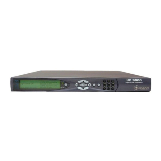
Section 3.1.1. The front panel also contains the WARNING and PWR/FAIL LEDs that operate as status indicators (see details in Section 3.1.1). Figure 1-2 illustrates the UE-9000 Series front panel. . Figure 1-2: Front View Scopus Documents (P/N 100673) Page 1-7... -
Page 32: Rear Panel
The rear panel contains all required input and output connectors. The AC connector and power switch are also located on the rear panel. The different UE-9000 Series modules present different rear panels, as requirements of inputs and connectors vary. The following images illustrate three examples of rear panels: •... -
Page 33: Figure 1-4: Ue-9217 Rear View - Dsng Module
UE-9000 Universal Encoder Platform Figure 1-4: UE-9217 Rear View – DSNG Module Figure 1-5: UE-9xx0 Rear View – IF Modulator Scopus Documents (P/N 100673) Page 1-9... -
Page 34: Figure 1-6: Ue-9500 Rear View - Audio-Only Module
User Manual Overview Figure 1-6: UE-9500 Rear View – Audio-Only Module ASI Out-1 and ASI Out-3 are duplicates, and therefore are either both scrambled or both cleared. ASI Out-2 will stand the opposite to ASI Out-1 and ASI Out-3 state (in other words, when the two are scrambled ASI Out-2 is clear and vise versa). -
Page 35: Model Options
UE-9000 Universal Encoder Platform 1.5. ODEL PTIONS The following sections detail each UE-9000 Series module for basic and software-licensed features. The available modules in the UE-9000 Series are: • UE-9210 – MPEG-2 single encoder (see Section 1.5.1) • UE-9220 – MPEG-2 dual encoder (see Section 1.5.2) •... -
Page 36: Ue-9210 Interfaces And Features
User Manual Overview 1.5.1. UE-9210 Interfaces and Features The UE-9210 is an MPEG-2 encoder supporting a single video-channel – C/V Channel 1 and two analog or four digital audio channels. The UE-9210 basic and software-licensed features are the following: Basic Features Software-Licensed Features •... -
Page 37: Ue-9220 Interfaces And Features
• Linear PCM and Dolby E audio • Up to 3 ASI outputs pass-through • Passive ASI loop-through • Web-management • GPI dry contact alarm output • VBI processing: CC, WSS, VITC, and Teletext Scopus Documents (P/N 100673) Page 1-13... -
Page 38: Ue-9217 Interfaces And Features
User Manual Overview 1.5.3. UE-9217 Interfaces and Features The UE-9217 is an MPEG-2 encoder supporting a single video-channel and DVB-S interface. The UE-9217 basic and software-licensed features are the following: Basic Features Software-Licensed Features • • 1 video-channel encoding DVB-DSNG 8PSK/16QAM MPEG-2 modulation •... -
Page 39: Ue-9310 Interfaces And Features
(Musicam and AAC), Dolby Digital 5.1 pass-through with configurable analog, digital, • Linear PCM and Dolby E audio and embedded sources pass-through • VBI processing: CC, VPS, WSS, VITS, and Teletext • Web-management Scopus Documents (P/N 100673) Page 1-15... -
Page 40: Ue-9318 Interfaces And Features
User Manual Overview 1.5.5. UE-9318 Interfaces and Features The UE-9318 is an MPEG-2 and H.264 upgradeable encoder supporting a single video-channel and DVB-S2 interface. The UE-9318 basic and software-licensed features are the following: Basic Features Software-Licensed Features • • 1 video-channel encoding MPEG-2 H.264 video compression (can be concurrent to MPEG-2) •... -
Page 41: Ue-9410 Interfaces And Features
Up to 3 ASI outputs • Linear PCM and Dolby E audio • IP output pass-through • Passive ASI loop-through • GPI dry-contact alarm output • VBI processing: CC, WSS, VITC, and Teletext • Web-management Scopus Documents (P/N 100673) Page 1-17... -
Page 42: Ue-9500 Interfaces And Features
User Manual Overview 1.5.7. UE-9500 Interfaces and Features The UE-9500 is an audio-only encoder supporting eight digital or four analog audio channels. The UE-9500 basic and software-licensed features are the following: Basic Features Software-Licensed Features • • Compression of up to 8 audio IP FEC channels (Musicam and AAC), •... -
Page 43: Characteristics And Capabilities
Interface – ITU-R 656 • SPECT ATIO 16:9 • • UDIO Input formats: Analog AES/EBU Embedded ASI I • NPUT Built-in multiplexer for encoder cascading • Passive loop-through for cascading redundancy • Up to 40 bps Scopus Documents (P/N 100673) Page 1-19... -
Page 44: Outputs
Level – 1.0 Vpp • Impedance – 75Ω unbalanced • Interface – ITU-R 624 Sync-Clock is available for units supporting audio pass-through, and therefore must be requested by the customer upon ordering the unit from Scopus. 1.6.2. Outputs EATURE APABILITIES ASI O •... - Page 45 • ODULATOR IF output 70 to 140 MHz (50 to 180 MHz) • Output power ranges from -35 dBm to 5 dBm – 1 dB step • L-band monitor 950 dBm at IF frequency Scopus Documents (P/N 100673) Page 1-21...
-
Page 46: Capabilities
User Manual Overview 1.6.3. Capabilities EATURE APABILITIES • ROCESSING IDEO Video encoding formats: MPEG-2 4:2:0 MP@ML MPEG-2 4:2:2 MP@ML H.264 4:2:0 MP@level3 Low delay mode (available for both formats) • Video encoding rates: 4:2:0 – Up to 15 Mbps 4:2:2 – 5Mbps to 50 Mbps •... - Page 47 Advanced Multiplexing – Up to 5 multi-services • Encoding and multiplexing is compliant with: ISO/IEC 13818(MPEG-2) DVB MPEG-2 implementation guidelines (DVB 001) • UDIO IDEO ELAY Delay Range – ±300mSEC • DNR selectable per video-channel (optional) Scopus Documents (P/N 100673) Page 1-23...
-
Page 48: Control And Monitoring
User Manual Overview 1.6.4. Control and Monitoring EATURE APABILITIES • EMOTE Web-based management through 100 Base-T interface • NMS-7000 communication (through SNMP), management through 100 Base-T interface • OCAL Front panel contains: Graphic rear-lit LCD Easy access keys Alphanumeric Touch Pad •... -
Page 49: Power And Physical Specifications
UE-9217 – Up to 70 W (with 24V = on add 14 W) • UE-9310 – Up to 60 W • UE-9318 – Up to 75 W (with 24V = on add 14 W) • UE-9410 – Up to 60 W Scopus Documents (P/N 100673) Page 1-25... -
Page 50: Environment
User Manual Overview 1.6.7. Environment EATURE APABILITIES • EMPERATURE Operating – 0°-50° C • Storage – (-)20°-70° C UMIDITY 85% on-condensing RESSURE From -200 ft. up to 10,000 ft. 1.6.8. Compliance EATURE APABILITIES FCC part 15, subpart B class A •... -
Page 51: Installation
Do not move or ship equipment unless it is correctly packed in its original wrapping and shipping containers. • Only Scopus trained personnel can undertake equipment service and maintenance. • To prevent damage by lightning, ground the unit according to local regulations. -
Page 52: Inventory Check
HECK Before installation ensure that all the equipment has arrived. Check the received parts for damage, according to the following list: UANTITY UE-9000 Universal Encoders platform AC Power Cable (for AC-powered encoders) 1 of the following: • European code cable (Euro) •... -
Page 53: Site Preparation
For any rack installation, ensure the rack is correctly grounded. OTES • In case of rack installation, ensure that a designated 19" rack is fully prepared for installation. • Ensure sufficient space behind the rack for easy access for installation and maintenance procedures. Scopus Documents (P/N 100673) Page 2-3... -
Page 54: Mechanical Installation
2.4. ECHANICAL NSTALLATION The following sections detail the installation of a UE-9000 unit in a 19" rack using the Scopus mounting slides. 2.4.1. Installation in 19" Rack Before installing the unit within the rack, ensure sufficient space behind the rack and easy access fro installation and maintenance procedures. -
Page 55: Mechanical Rack Installation
(see Figure 2-1). The brackets are fastened with screws on the sides of the UE-9000 Chassis. To prepare the UE-9000 for rack installation, fasten the brackets to the rack side rails with four screws (not included in the kit), two in on each side. -
Page 56: Figure 2-2: Encoders Mounted In A Single Rack
User Manual Installation PACING ECOMMENDATION A fully loaded 19”/42U rack is recommended to be mounted with UE-9000 as follows: 1. Use the special brackets detailed in Section 2.4.2. 2. Mount the UE-9000 in groups of five units per mounting bracket. -
Page 57: Compact Flash Installation
CARD AILING TO DO SO CAN RESULT IN CURRUPTION OF DATA ON THE CARD 1. Open the plastic protector on the right side of the UE-9000 front panel. 2. Firmly insert CF card into the drive to ensure contact. Scopus Documents (P/N 100673) -
Page 58: Electrical Installation
Connecting an AC power cable to the UE-9000 AC connector makes the encoder ground connection. If the UE-9000 is fitted with a –48V DC power supply, follow section 2.6.1.2. When the UE-9000 is rack mounted, the jackscrew (see Figure 2-4) must be connected to the rack housing, which in turn must be correctly grounded. -
Page 59: Figure 2-4: Power Supply Jack Screw Ground Connection
ONNECTING TO OWER OURCE 1. Connect the AC power cable to the UE-9000 power connector on the rear (see Figure 2-4). 2. Connect the other end of the cable to the AC power source. 2.6.1.2. DC Power and Ground Connections The -48 DC power and ground connections to the encoder must be supplied by an external 48v DC power supply. -
Page 60: Initialization And Configuration
2.7. NITIALIZATION AND ONFIGURATION Prior to powering up the UE-9000, ensure that all cabling is correctly connected (see Section 2.6). Verify that the unit is connected to the mains power supply and grounded according to the instructions. 2.7.1. Powering Up Prior to powering-up, verify that the Compact Flash card is in place and correctly installed. -
Page 61: Initial Configuration
In order to establish connection and start initial configuration of the encoder, perform the following: 1. Connect an Ethernet cable connection from the UE-9000 unit to a PC station or a VLAN connection. The Ethernet cable is connected to the Ethernet management port (see Figure 2-5). -
Page 63: Control Interfaces
3.1. RONT ANEL ONTROL NTERFACE The front panel of the UE-9000 provides extensive local control abilities along with convenient monitoring of status and operation. This section details the front panel. The section is divided into the following groups: • Control and Displays – Details the front-panel touchpad keys and their functions (see Section 3.1.1) -
Page 64: Controls And Displays
User Manual Control Interfaces 3.1.1. Controls and Displays The front panel interface allows the user to set the encoder parameters through the control elements, indicators, and display located on the front panel (see Figure 3-1). Figure 3-1: Front Panel The front panel contains the following display and control elements: •... -
Page 65: Figure 3-2: Alphanumeric Touch Pad
• Alphanumeric Touch Pad – The alphanumeric touch-pad is an efficient tool for entering both numbers and letters, when configuring menus and parameters. Figure 3-2 displays the alphanumeric touch-pad. Figure 3-2: Alphanumeric Touch Pad Scopus Documents (P/N 100673) Page 3-3... - Page 66 User Manual Control Interfaces • [1] To [9] Keys – Each alphanumeric key contains four to five different characters, encompassing the entire English alphabet. Selecting a specific character located in a certain key is performed by repeatedly pressing the key until the relevant character is displayed. [0 { { { { ] contains two characters, zero and space.
-
Page 67: Screen Types
(or green) for the visible four items and light grey for the scrolled items. The two screen-shot types are separated by a scroll icon ( ). The following sections detail the different front panel screen types. Scopus Documents (P/N 100673) Page 3-5... -
Page 68: Figure 3-3: Menu Navigation Screen Example
User Manual Control Interfaces 3.1.2.1. Menu Navigation Screen The Menu Navigation screen enables the user to navigate through the tree structure of the encoder. Although this menu may contain parameters, it is characterized by leading to other menus (see example in Figure 3-3). Configuration Configuration Configuration... -
Page 69: Figure 3-4: Edit Menu Screen Example
Press [Enter] to select the highlighted editable option (editable options are marked with a pencil icon: ); a parameter-editing screen is displayed. For information on the different Edit Screens, see Sections 3.1.2.4 - 3.1.2.5. Scopus Documents (P/N 100673) Page 3-7... -
Page 70: Figure 3-5: Table Menu Screen Example
User Manual Control Interfaces 3.1.2.3. Table Menu Screen The Table Menu screen displays multiple value information about the menu’s parameters using a table format. Some tables are configurable. This means that the user can select an item from the table and access an Edit Menu screen, which allows setting the entry values (see example in Figure 3-5). -
Page 71: Figure 3-6: Edit Value Screen Example
[Enter] they are not submitted. • Once setting a new value to a parameter, the user must save the changes within 60 seconds or the new configuration is lost. For details on saving the changes, see Section 4.1.1. Scopus Documents (P/N 100673) Page 3-9... -
Page 72: Figure 3-7: Select Value Screen Example
User Manual Control Interfaces 3.1.2.5. Select Value Screen The Select Value screen displays a list of values and enables the user to select one as the parameter’s new value (see example in Figure 3-7). Title Title Title Title Choice Choice Choice Choice 1 1 1 1... -
Page 73: Initializing The Front Panel
If all systems function, the Status OK message is displayed in the idle screen. Whenever an alarm is raised, the idle screen displays an Alarm Active message. Press [Enter]. The UE-9000 Root menu is displayed. • The following image displays the root menu of the UE-9210 unit:... -
Page 74: Web-Based Management Control Interface
(see Figure 3-8 for general view example). Figure 3-8: Web-Based Management Window – General View The web-based management is best viewed by Internet Explorer 6.0. Scopus cannot guarantee viewing quality in older IE versions or other web-browsers, such as FireFox, Opera, and so on. -
Page 75: Controls And Displays
In case of any additional parameters, such as advanced configuration parameters, another parameter-section is displays in the explorer window (see example in Figure 3-9). Figure 3-9: Web-Based Management Window – Status and Configuration Sections The following sections detail the different web-management display objects. Scopus Documents (P/N 100673) Page 3-13... -
Page 76: Figure 3-10: Web-Based Management Title
The following paragraphs detail the different sections: ITLE A static title to the web-based management, displays the Scopus logo and the device's type (UE-9000, see Figure 3-10). Figure 3-10: Web-Based Management Title ENU AND The tabs surround the explorer window section (see the following paragraph). -
Page 77: Figure
The parameters are listed in the explorer-window section. The list of parameters is framed with a light-blue line. If there is more than one parameters group, the different groups are listed in different frames. Each frame is titled according to its parameters group. Scopus Documents (P/N 100673) Page 3-15... - Page 78 User Manual Control Interfaces • Dynamic Sub-Menus and Parameters Section Display: The available sub-menus are listed on the left side of the explorer window (these lists are usually dynamic, and may allow adding and dropping entries to the list). When selecting a hyperlink from the list, the hyperlink is highlighted and its related parameters sections are displayed on the right-side of the explorer window.
-
Page 79: Figure
These buttons allow the user to save or drop changes, and the bar is displayed at all times (see Figure 3-13. For specific information about the buttons see Section 3.2.1.2. Figure 3-13: 'Save' Bar Scopus Documents (P/N 100673) Page 3-17... -
Page 80: Figure 3-14: Main-Menu Tabs
User Manual Control Interfaces 3.2.1.2. Control Elements The different display sections use different control elements to navigate, view, and manage the UE-9000 configuration. The following paragraphs detail these sections. The main-menu tabs are light-blue tabs that allow the user to select... -
Page 81: Figure
The hyperlinks allow the user to add new encoded service to the service list. In such cases, the hyperlink does not lead to a new parameter-explorer window but displays the parameters-sections in the same explorer window (see Figure 3-17). Figure 3-17: Dynamic Hyperlinks' List Scopus Documents (P/N 100673) Page 3-19... -
Page 82: Figure 3-18: Edit-Value Parameter
User Manual Control Interfaces ALUE ARAMETER The parameters-sections in the explorer window display lists of editable parameters, available for user-configuration. The edit-value parameters provides a free-text field for the user to type the required value (from within a given range). The edit-value parameter is divided into two sections: •... -
Page 83: Figure 3-20: Save Changes Button
The 'Save' bar (see Section 3.2.1.1) holds the 'Refresh' button. Clicking this button refreshes the web-page. This is useful for updating changes that were configured in the front-panel. This button is available at all times. Figure 3-22: Refresh Button Scopus Documents (P/N 100673) Page 3-21... -
Page 84: Initializing The Web-Based Management
Once the IP address is set and known, the user can access to the web- management (see details on Section 3.2.2.2). When powering up the device, the Ethernet Management port addresses display default values. Scopus strongly recommends the user to change these default parameters as soon as possible, to prevent information-security problems. Page 3-22... - Page 85 UE-9000 Universal Encoder Platform 3.2.2.1. Configuring the Ethernet Parameters 1. Power up the UE-9000. Wait for the LCD screen to display the initialization screen: Rate 4.620 Res F720 Rate 4.620 Res F720 Rate 4.620 Res F720 Rate 4.620 Res F720...
-
Page 86: Figure 3-23: Ip Address Field
The web-based management is supported and can be operated through most web browsers. However, Scopus recommends Internet Explorer 5.0 and higher for optimal operation. 2. Enter the UE-9000 IP Address in the Address field, in the following format: http://xxx.xxx.xxx.xxx (where xxx.xxx.xxx.xxx is the IP address of the Management port). -
Page 87: Operation And Management
(such as alarms status, permissions list, and so on. See Section 4.6) The front panel control interface contains all the existing UE-9000 control parameters, while the Web-Management interface allows easy access to the same parameters from a remote computer. Therefore these two interfaces are intertwined. -
Page 88: Saving Configuration
ONFIGURATION Whether it's entering new parameters through the front panel or submitting them through the web, many UE-9000 configuration procedures require saving. Changes in the encoder can be saved within 60 seconds after the recent change. During these 60 seconds the UE control interfaces remind the user to save by a blinking LED (the Warning LED) on the front panel and a shifting background for the Save and Drop buttons in the web-management. -
Page 89: Front Panel Save Menu
4.1.1. Front Panel Save Menu The Save menu allows to user to save the recent configuration. When changing a parameter in the UE-9000, the Warning LED blinks green for 60 seconds. During this time, the user must access the Save menu and save the change. -
Page 90: Web-Based Management Save Procedure
User Manual Operation and Management 4.1.2. Web-Based Management Save Procedure Saving configurations in the web-based management differs from the equivalent procedure in the front panel. Saving is performed with two buttons on the button part of the explorer window – Save Changes and Drop Changes (see Figure 4-1). Figure 4-1: "Save Changes"... -
Page 91: Root Menu
(see details on Section 4.2.1). • The web-management "root menu" is the Main screen, a working space displaying all menu tabs and their parameters and settings in the explorer window (see details on Section 4.2.2). Scopus Documents (P/N 100673) Page 4-5... -
Page 92: Front Panel Root Menu
User Manual Operation and Management 4.2.1. Front Panel Root Menu The front panel menu tree begins with the Root menu, which is a menu-navigation screen that leads to the four main menus: • • Preset Configuration • • Modulation and Up-Converter Status. -
Page 93: Figure 4-4: Ue-9000 Root Menu Tree
UE-9000 Universal Encoder Platform Figure 4-4 illustrates the front panel tree structure from the Root menu. Figure 4-4: UE-9000 Root Menu Tree The Modulator Menu is available for encoder modules equipped with a modulator card. Scopus Documents (P/N 100673) Page 4-7... -
Page 94: Web-Based Management Main Screen
User Manual Operation and Management 4.2.2. Web-Based Management Main Screen The Web-Based Management Main screen is the work space of web- management user. It displays the explorer window section, around which are the menu-tabs and sub-menu-tabs of the encoder (see Figure 4-5). Figure 4-5: Web-Based Management Display –... -
Page 95: Test
UE-9000 Universal Encoder Platform Figure 4-6 illustrates the Root Menu of the UE-9000 web-based management. The figure is divided into different sections, displaying the main and sub-menus of the Configuration section as well as the informative tables in the Status section. -
Page 96: Preset Menu
Operation and Management 4.3. RESET The Preset menu allows the user to save, load, delete, and rename the UE-9000 preset files, containing the setup parameters. The Preset menu contains the following menus (see tree structure in Figure 4-7): • Recall Menu – Allows the user to load a preset file (see Section 4.3.1). -
Page 97: Recall Menu
2 2 2 2 To access the Recall menu, in the web-based management select tabs Preset Recall (see Figure 4-8). Figure 4-8: Recall Preset Menu Display The following sections detail the Recall menu options and parameters. Scopus Documents (P/N 100673) Page 4-11... -
Page 98: Test
User Manual Operation and Management ELECT RESET RECALL The Select Preset Name parameter allows the user to select a preset file to load. This option displays a list of saved preset files, including the factory-default preset. To set the Select Preset Name option, in the front panel select Root Preset Recall Select Preset Name (see the following example). -
Page 99: Save Current Preset Menu
Specify Preset Name Specify Preset Name Specify Preset Name 2 2 2 2 To access the Save menu, in the web-based management select tabs Preset Save (see Figure 4-9). Figure 4-9: Save Preset Menu Display Scopus Documents (P/N 100673) Page 4-13... - Page 100 User Manual Operation and Management 4.3.2.1. Override Existing Menu The Override Existing menu allows the user to save the current parameter setup configurations into an existing preset file, erasing the former parameters setup. access Override Existing menu, front panel select Root Preset Override Existing (see the following example).
-
Page 101: Test
To set the Save Preset option, in the front panel select Root Preset Save Current Override Existing Preset Save Preset. To activate the Save option, in the web-based management click [Enter] to approve the selection. Scopus Documents (P/N 100673) Page 4-15... - Page 102 User Manual Operation and Management 4.3.2.2. Specify Preset Name Menu The Specify Preset Name menu allows the user to save the current setup parameters as a new preset file. To access the Specify Preset Name menu, in the front panel select Root Preset Specify Preset Name (see the following example).
- Page 103 To set the Save Preset option, in the front panel select Root Preset Save Current Specify Preset Name Save Preset. To activate the Save option, in the web-based management click [Enter] to approve the selection. Scopus Documents (P/N 100673) Page 4-17...
-
Page 104: Delete Menu
User Manual Operation and Management 4.3.3. Delete Menu The Delete menu allows the user to delete an existing preset file from the preset files list. To access the Delete menu, in the front panel select Root Preset Delete (see the following example). Delete Delete Delete... - Page 105 After executing the delete option, the display returns to the Preset menu screen. To set the Delete Preset option, in the front panel select Root Preset Delete Delete Preset. To activate the Delete option, in the web-based management click [Enter] to approve the selection. Scopus Documents (P/N 100673) Page 4-19...
-
Page 106: Rename Menu
User Manual Operation and Management 4.3.4. Rename Menu The Rename menu allows the user to rename an existing preset file from the preset files list. To access the Rename menu, in the front panel select Root Preset Rename (see the following example). Rename Rename Rename... - Page 107 The available options are the current preset files in the file list. The default factory preset file cannot be renamed. To set the Select Preset Name parameter, in the web-based management select tabs Preset Rename. Scopus Documents (P/N 100673) Page 4-21...
- Page 108 User Manual Operation and Management PECIFY RESET RENAME The Specify New Preset Name parameter allows the user to set the new preset file name. This option displays an edit-value screen that allows entering the new filename using the alphanumeric touch-pad with free text. In the web- management, enter the new filename into the free-text field.
Need help?
Do you have a question about the UE-9000 and is the answer not in the manual?
Questions and answers