
Related Manuals for Scopus CODICO IRD-2600


Summary of Contents for Scopus CODICO IRD-2600
-
Page 1: User Manual
® CODICO IRD-2600 / IRD-2800 INTEGRATED RECEIVER DECODERS User Manual P/N 2349-72784-00 (Rev. B / December 2001) - Page 2 © 2001 Scopus Network Technologies Ltd. All rights reserved. Scopus Network Technologies Ltd. Reserves the rights to alter the equipment specifications and descriptions in this publication without prior notice. No part of this publication shall be deemed to be part of any contract or warranty unless specifically incorporated by reference into such contract or warranty.
-
Page 3: Introduction
Scopus Network Technologies Ltd. takes great pride in delivery of its products, and makes every endeavor to ensure its clients full satisfactory. On behalf of all the Scopus team, we would like to extend our congratulations on your investment in the CODICO IRD-2600 and IRD-2800 Family of Integrated Receiver Decoders. -
Page 4: Technical Support
Scopus Network Technologies Support will assign a RMA Tracking Number; this must accompany the item being returned and will be referred to in all correspondence. The item is sent to Scopus Network Technologies with the RMA Number included in the accompanying documentation (shipping and customs forms). - Page 5 SCOPUS Network Technologies Ltd. facilities, of any Product or parts thereof that do not conform to SCOPUS Network Technologies Ltd. published specifications or that are defective in material or workmanship, as specified above.
-
Page 6: The Fcc Wants You To Know
User Manual Front Matter FCC Compliance Notice Trade Name Scopus Product Name Integrated Receiver Decoder ® Product Model Number CODICO IRD-2600 ® Product Model Number CODICO IRD-2800 These devices comply with Part 15 of the FCC Rules. Operation is subject to the following two conditions: 1. -
Page 7: Table Of Contents
IRD-2600 / IRD-2800 Integrated Receiver Decoders TABLE OF CONTENTS LIST OF FIGURES ..........................viii LIST OF TABLES............................. x Overview ..........................1-1 1.1. General Information....................1-1 1.1.1. Highlights and Benefits ................1-1 1.1.1.1. Inputs..................1-2 1.1.1.2. Outputs..................1-3 1.1.1.3. Conditional Access..............1-4 1.1.1.4. - Page 8 User Manual Front Matter 2.4.5.2. AC Power Connector...............2-7 2.4.5.3. DC Power Connector...............2-7 2.5. System Expansion ....................2-8 2.5.1. Cascade Loopthrough Output ..............2-8 2.5.2. ASI Loopthrough Cascade ................2-9 2.5.3. RS-485 Master-Slave Connection.............2-9 2.6. Initialization And Configuration ................2-10 2.6.1. Powering Up ....................2-10 2.6.2. Initialization Sequence................2-10 2.6.3.
- Page 9 IRD-2600 / IRD-2800 Integrated Receiver Decoders 4.4.3. BIT Stream Warning Messages ..............4-5 4.4.4. Service Warning Messages ..............4-6 Appendix A. Operational Menu Trees....................1 Appendix B. LNB Theory Of Operation..................11 Why is an LNB needed?.................... 11 Frequency Calculation IRD + LNB ................11 Use of a Splitter or Distribution (band) Amplifier ............
-
Page 10: List Of Figures
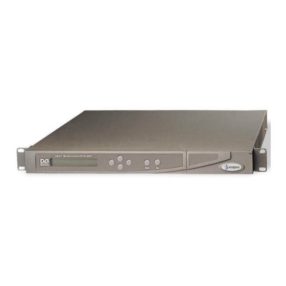
User Manual Front Matter LIST OF FIGURES Figure 1-1: IRD-2600 and IRD-2800 - General View .............. 1-1 ® Figure 1-2: CODICO Integrated Product Line ................ 1-7 Figure 1-3: Signal Path in the IRD-2600 and IRD-2800............1-8 Figure 1-4: Front View of the IRD-2600/IRD-2800..............1-12 Figure 1-5: IRD-2600\IRD-2800 Rear Panel Section ............ - Page 11 IRD-2600 / IRD-2800 Integrated Receiver Decoders Figure 3-30: Product Status / Product Configuration Overlay - Example ........ 3-63 Figure 3-31: Product Status / Product Revision Overlay - Example ........3-64 Figure 3-32: Product Status / Product Setups Overlay - Example........... 3-64 Figure 3-33: Stream PSI/SI / Program Association Table (PAT) Overlay -Example ....
- Page 12 User Manual Front Matter LIST OF TABLES ® Table 1-1: CODICO Product Family..................1-7 Table 1-2: IRD-2600 / IRD-2800 Configuration Options ............1-11 Table 1-3: Rear Panel –Receiver Front End Option Cards ..........1-13 Table 1-4: IRD-2600/IRD-2800 Output Option..............1-14 Table 1-5: QPSK Input Features and Specifications ............
-
Page 13: Overview
IRD-2600 / IRD-2800 Integrated Receiver Decoders OVERVIEW 1.1. General Information ® ® The CODICO IRD-2600 and IRD-2800 are a new generation of the 4:2:0 / 4:2:2 CODICO family of Integrated Receiver Decoders. Both IRD-2600 and IRD-2800 are suitable for SCPC and MCPC 4:2:0 applications;... -
Page 14: Inputs
User Manual Chapter 1. Overview 1.1.1.1. Inputs Decoder Inputs RS-422 Clock/Data Input DVB-ASI with Loop-through (optional) • Interface: Copper or Optical • TS bit rate: up to 54 Mbps Receiver Input Options DVB Satellite (QPSK) Front End • Frequency range: 950 -2150 MHz •... -
Page 15: Outputs
IRD-2600 / IRD-2800 Integrated Receiver Decoders 1.1.1.2. Outputs • Video Analog video Interfaces: 2 composite, 1 S-Video • Digital video Interfaces (optional): 2x SDI, with embedded VBI and up to 2 stereo channels • Video formats: PAL-B/G/I/M/N/D, NTSC/SECAM L/B/G/K1 • Russian SECAM D/K (option applicable only in composite video, available only for IRD-2600). -
Page 16: Conditional Access
User Manual Chapter 1. Overview 1.1.1.3. Conditional Access DVB-Descrambling • BISS Mode-1 • BISS-E • CAS-5000 DVB-CI • Interface:2 CI slots – EN—50221 • CA Method: Multicrypt, Simulcrypt ® ® ® ® • CAS: Irdeto , Viaccess , Cryptoworks , Conax ®... -
Page 17: Applications
IRD-2600 / IRD-2800 Integrated Receiver Decoders 1.1.2. Applications The IRD-2600 and IRD-2800 Integrated Receiver Decoders can be implemented in a wide range of applications. The following is a list of some of the typical uses for the IRD-2600 and IRD-2800: •... -
Page 18: Descrambling
DVB-CI Common Interface slots. The internal DVB Descrambler is usable for: ® • Scopus CAS-5000 Encrytion system (CODICrypt • DSNG-CA (BISS) fixed Key Encryption system and BISS-E. The DVB-CI deciphers encrypted signals from a DVB signal source, by means of an authorized Smart Card and a CA-specific CAM (Conditional Access Module). -
Page 19: Product Line
IRD-2600 / IRD-2800 Integrated Receiver Decoders 1.1.3. Product Line The IRD-2600 / IRD-2800 Integrated Receiver Decoders are an integral member of the advanced CODICO product line. The CODICO product family offers comprehensive solutions for both transmission sites and reception stations. In addition, it is the most cost-effective solution for TV broadcasting applications. -
Page 20: Functional Description
User Manual Chapter 1. Overview 1.2. Functional Description 1.2.1. IRD-2600 and IRD-2800 Block Diagram Input to the Receiver (QDSNG receiver, QPSK, QAM, G.703, DS3/ATM and STM-1/OC-3) is transferred to the de-multiplexer in the MPEG-2 Transport Demux. A video decoder and an audio decoder process the resulting video, audio and data streams. -
Page 21: Basic Configuration
Audio (1st channel): one stereo pair, balanced output via XLR connectors; volume adjustment. • Data channel: High-Speed Data @ RS-422 and Low-Speed Data @ RS-232 • DVB descrambling, SimulCrypt Support, Scopus CAS-5000 descrambling, BISS DSNG-CA • Over the air remote control; Over the air software upgrade •... -
Page 22: Receiver Front End Options
User Manual Chapter 1. Overview 1.2.3. Receiver Front End Options The IRD-2600 / IRD-2800 are delivered in various front-end configurations. The following defines the specific features of each configuration, in addition to the basic features described in paragraph 1.2.2 above. DVB-S QPSK Receiver Front-End Option: •... -
Page 23: Configuration Options
IRD-2600 / IRD-2800 Integrated Receiver Decoders 1.2.4. Configuration Options Table 1-2 lists the configuration options available for the various IRD-2600/IRD-2800 Standard applications: Table 1-2: IRD-2600 / IRD-2800 Configuration Options OPTION NAME DESCRIPTION OPT 002 ASI Out Two BNC type ASI Output (provides full transport stream, with the selected service decrypted). -
Page 24: Mechanical Structure
User Manual Chapter 1. Overview 1.3. Mechanical Structure 1.3.1. Enclosure The IRD-2600 and the IRD-2800 are housed in a ruggedized industrial enclosure, 1U by 19" (Rack Mount). 1.3.2. Front Panel The front panel of the IRD-2600 and IRD-2800 allow control via a four-way touch pad, an Enter key, and an Escape key. -
Page 25: Rear Panel Option Cards
IRD-2600 / IRD-2800 Integrated Receiver Decoders 1.3.4. Rear Panel Option Cards Table 1-3 and Table 1-4 describe the various option cards available for the IRD-3600 and IRD-3800 Integrated Receiver Decoders. Table 1-3: Rear Panel –Receiver Front End Option Cards OPTION CARD DESCRIPTION DSNG RECEIVER FRONT-END RS422/GPI... - Page 26 User Manual Chapter 1. Overview Table 1-4: IRD-2600/IRD-2800 Output Option OPTION CARD DESCRIPTION BLANK OUTPUT PANEL This panel is supplied as default when no output option is ordered. Full With ASI In and OUT 3 Balanced Analog Audio over XLR or AES/EBU (SP-DIF) over XLR ASI IN + OUT Loopthrough Sync lock IN + OUT...
-
Page 27: Management
IRD-2600 / IRD-2800 Integrated Receiver Decoders 1.4. Management The IRD-2600 and IRD-2800 Integrated Receiver Decoder contain embedded software for control and configuration. The embedded software is accessible by the following interfaces: • IRD-2600/IRD-2800 Front Panel • Infrared Remote Control • PC terminal •... -
Page 28: Characteristics And Specifications
User Manual Chapter 1. Overview 1.5. Characteristics and Specifications 1.5.1. Receiver Input Specifications The following tables summarize the features and specifications of the various receiver input options available for the IRD-2600 and the IRD-2800 Integrated Receiver Decoder: • QPSK input option, see Table 1-5 •... - Page 29 IRD-2600 / IRD-2800 Integrated Receiver Decoders Table 1-6: DSNG Input Features and Specifications FEATURE SPECIFICATION Modulation and coding schems: QPSK, FEC rate 1/2, 2/3, 3/4, 5/6, 7/8. 8PSK, FEC rate 2/3, 5/6, 8/9. 16QAM, FEC rate 3/4, 7/8. Automatic modulation scheme recovery Symbol Rate 1 ≤...
- Page 30 User Manual Chapter 1. Overview Table 1-8: Telecom (G.703) Input Features and Specifications FEATURE SPECIFICATION 75 Ω Input Impedance Bit Rate Unframed E1 (2.048 Mbps), E2 (8.448 Mbps) and E3 (34.368 Mbps) G.703 Loop Through Output For cascading multiple IRD units. Loopthrough Output Mask according to G.703 recommendation De-Interleaving 17/12 (*)
-
Page 31: Output Specifications
IRD-2600 / IRD-2800 Integrated Receiver Decoders Table 1-11: SONET/SDH 155Mbit/s input (In accordance with ETS 300 814) Feature Specification STM-1 155.52Mbit/s (up to 60 Mbps for the selected TS) Description: Single-mode/Multi-mode optical interface Frame: STM-1/OC-3 Connectors: Duplex SC fiber optic Wavelength: 1300 nm Max selected TS bit rate... -
Page 32: Table 1-13: Audio Output Features And Specifications
User Manual Chapter 1. Overview Table 1-12: Video Decoder Output Features and Specifications FEATURE SPECIFICATION Encoded Input Resolution of [Horizontal] by [Vertical] at [Frequency] the IRD-2800 720, 704, 544, 30 Hz 480, 352 30 Hz 720, 704, 544, 25 Hz 480, 352 25 Hz 4:2:2 Mode Only... -
Page 33: Control Ports Specifications
IRD-2600 / IRD-2800 Integrated Receiver Decoders 1.5.3. Control Ports Specifications The IRD provides connections for terminal control on the IRD over RS-232 interface or RS-485 Interface. Table 1-14 details the interface specifications. Table 1-14: RS-232 Interface Specifications PARAMETER SETTING Protocol XON/XOFF Baud Rate 9600, 19200, 38400, 57600, 115200... -
Page 35: Installation
IRD-2600 / IRD-2800 Integrated Receiver Decoder User Manual CAUTION If anything is missing or damaged, do not continue with the installation. Refer to the “TECHNICAL SUPPORT” procedures in the front of this manual for Scopus support. P/N 2349-72784-00 Page 2-1... -
Page 36: Site Preparation
User Manual Chapter 2. Installation 2.2. Site Preparation NOTE If the IRD is to be installed in a standard 19" rack, make sure the rack fully prepared for the installation. The IRD should be installed within 1.5m (5 feet) from an easily accessible grounded AC outlet, capable of furnishing the required supply voltage as detailed below: The use of an UPS (Uninterrupted Power Supply) and an AVR (Automated Voltage Regulation) is highly recommended to ensure proper operation of the IRD. -
Page 37: Insertion Of The Dvb-Ci Module (Pcmcia)
IRD-2600 / IRD-2800 Integrated Receiver Decoders 2.3.2. Insertion of the DVB-CI Module (PCMCIA) Figure 2-1 shows the IRD with DVB-CI Module (PCMCIA card) and the Smart Card used to decrypt the incoming signal. The IRD is provided with two PCMCIA slots for up to two DVB-CI Modules. -
Page 38: Cable Connections
User Manual Chapter 2. Installation 2.4. Cable Connections 2.4.1. IRD-2600 and IRD-2800 Connection Setup and Options This section describes the cable connections for ground, power, and interface cables connected to the rear panel of the IRD-2600 and IRD-2800 Integrated Receiver Decoders. The IRD-2600 or the IRD-2800 are ordered with a specific configuration to suit the requirements of a specific application. -
Page 39: Front End Panels
IRD-2600 / IRD-2800 Integrated Receiver Decoders 2.4.2. Front End Panels All front-end panels provide an RS-422/GPI connector for the input transport stream to the IRD. Table 2-1 describes the functionality of the signals available on the connector. Table 2-1: RS-422 Serial Input/GPI Pin Out Designations DESIGNATION DESIGNATION Clock Return (-) -
Page 40: Terminal Control And Data Connections
User Manual Chapter 2. Installation 2.4.4. Terminal Control and Data Connections The IRD supports terminal control from a standard PC via a Serial RS-232 or RS-485 cable. Table 2-3 and Table 2-4 detail the pin-to-pin and signal assignment of the RS-232 and RS-485 cables, respectively. -
Page 41: Power Connection
IRD-2600 / IRD-2800 Integrated Receiver Decoders 2.4.5. Power Connection 2.4.5.1. Ground Connection Ground connection to the IRD is made by connecting an AC power cable to the IRD AC connector. If the IRD is fitted with a –48V DC power supply please follow the instruction provided under paragraph 2.4.5.3 below. -
Page 42: System Expansion
User Manual Chapter 2. Installation 2.5. System Expansion This section provides instructions for system expansion through inter-connection of multiple IRD-2600 and IRD-2800 Integrated Receiver Decoder units by daisy chaining the units.. It is assumed that all IRD units are configured and operational. The IRD supports two Loopthrough methods: •... -
Page 43: Asi Loopthrough Cascade
IRD-2600 / IRD-2800 Integrated Receiver Decoders 2.5.2. ASI Loopthrough Cascade Connect the input signal to the bottom IRD ASI input (BNC). Cascade the remaining units as shown in Figure 2-6. Figure 2-6: IRD Cascade with ASI Loopthrough AES/EBU 100-240VAC 1A DS3[ ] E3[ ] E2[ ] E1[ ] AES/EBU1 AES/EBU2... -
Page 44: Initialization And Configuration
User Manual Chapter 2. Installation 2.6. Initialization And Configuration Prior to powering up the IRD-2600 or IRD-2800 Integrated Receiver Decoder, ensure that all cabling is correctly connected as explained in Section 2.4. Ensure that the unit is connected to the mains power supply and grounded according to instructions. 2.6.1. - Page 45 IRD-2600 / IRD-2800 Integrated Receiver Decoders For DSNG Front/End Receiver to the IRD-2600 / IRD-2800, proceed with Table 2-7. For QPSK Front/End Receiver to the IRD-2600 / IRD-2800, proceed with Table 2-8. For QAM Front/End Receiver to the IRD-2600 / IRD-2800, proceed with Table 2-9. Refer to chapter 3: Operation for instructions on all other input types as well as for Decoder Only operation, configuration and/or changing the device Product Type.
- Page 46 User Manual Chapter 2. Installation Table 2-8: QPSK Receiver Configuration Procedure SEQ. MENU DISPLAY MESSAGE PROCEDURE RECEIVER CONFIGURATION The CONFIG sub menu is displayed. Function Start. Select the RECEIVER option and proceed to configure as described below. Frequency Range Parameter Select Frequency Range option.
-
Page 47: Serviceability Check
IRD-2600 / IRD-2800 Integrated Receiver Decoders 2.6.3. Serviceability Check After performing any installation, initialization, or configuration to the IRD-2600 or IRD-2800 Integrated Receiver Decoder, maintenance checks should be performed to ensure that the unit is serviceable. A Video Monitor must be connected to the IRD-2600 in order to perform the check. Table 2-10 provides a systematic instruction for performing a serviceability check. -
Page 49: Operation
Infrared Remote Control. The LCD on the panel displays the menus and options of the IRD embedded software. The Infrared Remote Control can be ordered through a local SCOPUS Network Technologies Ltd. product supplier. -
Page 50: Front Control Panel
User Manual Chapter 3. Operation 3.1.1.1. Front Control Panel Figure 3-1 shows the Front Control Panel of the IRD, its controls and features. Table 3-1 explains the operation of the items found on the Front Control Panel. NOTE This panel is identical for the IRD-2600 and for the IRD-2800. Figure 3-1: IRD-2600 / IRD-2800 Front Control Panel Enter Touch Pad... -
Page 51: Infrared Remote Control (Optional)
IRD-2600 / IRD-2800 Integrated Receiver Decoders 3.1.1.2. Infrared Remote Control (Optional) Figure 3-2 shows the optional infrared remote control available for the IRTD operation. Table 3-2 explains the control functions on it. Figure 3-2: IRD Infrared Remote Control Table 3-2: IRD Infrared Remote Control Items CONTROL FUNCTION... -
Page 52: Four Way Touch Pad
User Manual Chapter 3. Operation 3.1.1.3. Four Way Touch Pad. The four way touch pad on the Front Control panel (see Figure 3-1). Four way touch buttons on the optional Infrared Remote Control (see Figure 3-2) are used to navigate in the embedded software menus: •... - Page 53 IRD-2600 / IRD-2800 Integrated Receiver Decoders Table 3-3: IRD Front Panel Main Menu Options. MENU DESCRIPTION Configuration The Configuration Menu option enables access to the Receiver, Menu Decoder and System configuration parameters. These options are used to define or modify the IRD configuration: •...
-
Page 54: Configuration Menu
User Manual Chapter 3. Operation 3.2. Configuration Menu The Configuration Menu enables the IRD operator to set-up the specific configuration required of the IRD. Figure 4-1 shows the IRD Configuration Menu tree and the options available to the user. The IRD Front Panel display, controls and keypad are used to scroll through the menu, view the options available and set the parameters of the configuration functions provided. -
Page 55: Configuration / Receiver Menu
IRD-2600 / IRD-2800 Integrated Receiver Decoders 3.2.1. Configuration / Receiver Menu The IRD is provided in a wide range of input receivers: QPSK (DVB-S), DSNG (DVB-DSNG), QAM (DVB-C), G.703 (E1, E2, E3) and ATM (DVB-PDH, SDH)) receiver options. The Configuration / Receiver Menu is input sensitive (i.e., varies automatically according to the IRD Input option installed), and provides a group of functions to configure the receiver section of the IRD. - Page 56 User Manual Chapter 3. Operation Figure 3-5: DSNG Receiver Configuration Menu Tree Structure CONFIG RECEIVER DSNG QPSK G.703 Front End Front End Front End Front End Front End Frequency Range Frequency Range Input Signal Input Signal Input Signal Source Source Source Ku/C Band L Band...
- Page 57 IRD-2600 / IRD-2800 Integrated Receiver Decoders Table 3-4 Configuration/Receiver Menu Options OPTION DESCRIPTION Frequency Frequency Range Selector Range This parameter supports various frequency ranges for a satellite band range receiver. Two options are provided: L-Band: Receiving in the L-Band frequency range. Satellite (Ku/C) Band: Receiving in the Ku/C-Band frequency range.
- Page 58 User Manual Chapter 3. Operation Table 3-4 Configuration/Receiver Menu Options OPTION DESCRIPTION LNB 22KHz LNB 22 KHz Selector Turns ON and OFF the 22 KHz LNB. This action determines the band selected (ON = High Band, OFF = Low Band). In addition, the selection of the LNB Power Supply determines the polarization of the antenna.
- Page 59 IRD-2600 / IRD-2800 Integrated Receiver Decoders Table 3-4 Configuration/Receiver Menu Options OPTION DESCRIPTION VHF/UHF VHF/UHF-Band Frequency Selection Frequency Displays the expected carrier frequency of the received input signal at the QAM (DVB-C) application. Symbol Rate Symbol Rate Setup The Symbol Rate for a group of station programs is configured according to the broadcast program parameters and the specific ranges available in your IRD.
- Page 60 User Manual Chapter 3. Operation Table 3-4 Configuration/Receiver Menu Options OPTION DESCRIPTION Viterbi Rate Viterbi Rate Select This parameter is configured according to the information provided from the broadcast head end. The available values are: Auto, 1/2, 2/3, 3/4, 4/5, 5/6, 6/7, 7/8, 8/9. NOTE If the specific Viterbi rate is not provided, selecting the AUTO option enables the IRD to automatically detect the Viterbi rate.
- Page 61 IRD-2600 / IRD-2800 Integrated Receiver Decoders Table 3-4 Configuration/Receiver Menu Options OPTION DESCRIPTION ATM Mode ATM Receiver Mode Selection Selects the operational mode of the ATM receiver (According to the hardware installed. Options available: E3, Mode: Ds3 Mode, STM1 Multi-Mode, STM1 Single-Mode, Oc3 Multi/Single–Mode.
-
Page 62: Configuration / Decoder Menu
User Manual Chapter 3. Operation 3.2.2. Configuration / Decoder Menu The Decoder Configuration menu provides the IRD user the capability to setup and configure the decoder in the IRD. Figure 3-6 shows the menu tree of configuration functions available in the Decoder Configuration Menu (password is required only if it was enabled previously). - Page 63 IRD-2600 / IRD-2800 Integrated Receiver Decoders Figure 3-6: Decoder Configuration Menu Tree Structure Initialization Password Main Status Display CONFIG STATUS TEST RECEIVER DECODER SYSTEM STREAM VIDEO AUDIO 27 MHz C I Operation Audio Decoder Video Format Synchronization Enable Operation CI [slot1] PTS-PCR Video AC3 Sampling...
-
Page 64: Decoder / Stream Configuration Sub-Menu
User Manual Chapter 3. Operation 3.2.2.1. Decoder / Stream Configuration Sub-Menu The Decoder / Stream Configuration Sub-Menu provides an extended menu of setup and selection options to configure the decoder’s streams. Figure 3-7 shows the menu tree of configuration functions available in the Decoder / Stream Configuration Sub-Menu. - Page 65 IRD-2600 / IRD-2800 Integrated Receiver Decoders Table 3-5: Decoder / Stream Configuration Menu Options OPTION DESCRIPTION 27 MHz Synchronization Decoder Synchronization Source The IRD is synchronized by a 27MHz clock, generated by a Voltage Controlled Oscillator (VCXO). This function enables the user to select a synchronization source for the VCXO.Options available: Internal: The VCXO is factory calibrated to a fixed 27 MHz clock.
- Page 66 User Manual Chapter 3. Operation Table 3-5: Decoder / Stream Configuration Menu Options OPTION DESCRIPTION Data1-HSD PID Filtering Data1High Speed Data Filtering Options Selects the filtering applied to the Data1 (HSD PID) information: P.E.S Payload: Strips the headder of the Packetised Elementry Stream (PES). Entire Transport Packet: Enables the entire transport stream packet (188 bytes).
-
Page 67: Decoder/Ci Configuration Sub-Menu
IRD-2600 / IRD-2800 Integrated Receiver Decoders 3.2.2.2. Decoder/CI Configuration Sub-Menu The Decoder / Common Interface (CI) Configuration Sub-Menu provides setup and configuration options for the CI function. Figure 3-8 shows the menu tree for the Decoder / CI Configuration Sub-Menu. Table 3-6: Describes the Options in the Sub Menu. -
Page 68: Decoder / Video Configuration Sub-Menu
User Manual Chapter 3. Operation 3.2.2.3. Decoder / Video Configuration Sub-Menu The Decoder / Video Configuration Sub-Menu provides an extended menu of setup and selection options to configure the decoder’s video signal generated from the input data. Figure 3-9 shows the menu tree of configuration functions available in the Decoder / Video Configuration Sub-Menu. - Page 69 IRD-2600 / IRD-2800 Integrated Receiver Decoders Table 3-7: Decoder / Video Configuration Sub-Menu Options OPTION DESCRIPTION Video Format Video Format Selection Selects the output format of the video signal. Options available are: PAL N, PAL B/G, PAL M, NTSC, PAL D/I, SECAM Video Interpolation Video Interpolation Selection Selects the interpolation format of the output video signal.
- Page 70 User Manual Chapter 3. Operation Table 3-7: Decoder / Video Configuration Sub-Menu Options OPTION DESCRIPTION Teletext Subtitling Page Teletext Subtitling Select Selects a page number for the EBU Teletext Subtitling. Options available are: 100, through 899. NOTES: The Teletext Subtitling function is available ONLY when the PID mode is activated.
-
Page 71: Decoder / Audio Configuration Sub-Menu
IRD-2600 / IRD-2800 Integrated Receiver Decoders 3.2.2.4. Decoder / Audio Configuration Sub-Menu The Decoder / Audio Configuration Sub-Menu provides an extended menu of setup and selection options to configure the decoder’s audio signals generated from the input data. Figure 3-10 shows the menu tree of configuration functions available in the Decoder / Audio Configuration Sub-Menu. - Page 72 User Manual Chapter 3. Operation Table 3-8: Decoder / Video Configuration Sub-Menu Options OPTION DESCRIPTION Audio Decoder Audio Decoder Operation Operation Selects the digital audio operation mode. Available options: MPEG: Musicam Decoding AC3 Passthru (IEC 1937): Digital output only. Linear PCM Audio: Available only in the IRD-2800. AC3 Sampling AC3 Sampling Frequency Select Frequency...
-
Page 73: Configuration/System Menu
IRD-2600 / IRD-2800 Integrated Receiver Decoders 3.2.3. Configuration/System Menu The System Configuration Menu provides the IRD user the capability to set-up and configure the IRD operation. Figure 3-11 shows the menu tree of system level configuration functions available in the System Configuration Menu (password is required only if it was enabled previously). - Page 74 User Manual Chapter 3. Operation Table 3-9: System Configuration Menu Options OPTION DESCRIPTION Display Contrast Display Contrast Level Set-Up Controls the display contrast of the LCD display on the front panel of the IRD. Contrast level is set as follows: The [up] touch-pad increases the contrast level, and The [down] touch-pad to decreases the contrast.
- Page 75 IRD-2600 / IRD-2800 Integrated Receiver Decoders Table 3-9: System Configuration Menu Options OPTION DESCRIPTION Control Port Baud Rate Control Port Rate Select Selects the Baud rate of the RS-232/RS-488 Control Port. Available options: 9600 Baud, 19200 Baud, 38400 Baud, 57600 Baud, 115200 Baud Control Port Address Control Port Address Set-Up Sets the address of the RS-232/RS-488 Control Port.
- Page 76 User Manual Chapter 3. Operation Table 3-9: System Configuration Menu Options OPTION DESCRIPTION Session Word Session Word Setup Sets the session word for BISS encryption word value (8 digits Hex word), for all BISS CA encryption modes NOTE This option is NOT available when the EVEN-ODD DSNG-CA Encryption mode is selected.
-
Page 77: Status Menu
IRD-2600 / IRD-2800 Integrated Receiver Decoders 3.3. Status Menu The Status Menu enables the IRD operator to monitor specific functions and activities in the IRD. Figure 3-12 shows the IRD Status Menu tree and the options available to the user (password is required only if it was enabled previously). -
Page 78: Status / Receiver Menu
User Manual Chapter 3. Operation 3.3.1. Status / Receiver Menu The IRD is provided in a wide range of input receivers; QPSK (DVB-S), DSNG (DVB-DSNG), QAM (DVB-C), G.703 (E1, E2, E3) and ATM (DVB-PDH) input options. The Status / Receiver Menu is input sensitive (i.e., varies automatically according to the IRD Input option installed), and provides a group of functions to monitor the input section of the IRD. - Page 79 IRD-2600 / IRD-2800 Integrated Receiver Decoders Figure 3-13: DSNG Receiver Status Menu Tree Structure STATUS RECEIVER DSNG QPSK Front End Front End Front End Front End Signal Quality Signal Quality Signal Quality ATM Bit Channel Bit ATM Input Eb/N0 Eb/N0 Error Rate Rate Frequency...
- Page 80 User Manual Chapter 3. Operation Table 3-10: Receiver Status Menu Parameters OPTION DESCRIPTION Signal Quality Signal Quality Indicator Displays the quality of the input signal as a bar. The longer the bar, the stronger the signal. The indicator may be used to position the antenna to obtain optimal signal quality.
- Page 81 IRD-2600 / IRD-2800 Integrated Receiver Decoders Table 3-10: Receiver Status Menu Parameters OPTION DESCRIPTION Frequency Tune Tune Frequency Received Displays the tuner programmed frequency of the signal received at the IRD (as set in the Receiver Configuration Menu, see paragraph 3.2.1). Number given in KHz. NOTE When the Frequency Drift Compensation function is activated, the displayed frequency is adjusted by the frequency offset...
-
Page 82: Status / Decoder Menu
DESCRIPTION ATM Bit CAUTION Advanced status functions to be operated ONLY by the authorized Scopus personnel. Unauthorized operation may create in unpredicted results. ATM Input Rate ATM IRD Input Modulation Displays the input rate active at the ATM IRD receiver (as set in the Receiver Configuration Menu, see paragraph 3.2.1). -
Page 83: Figure 3-14: Decoder Status Menu Tree Structure
IRD-2600 / IRD-2800 Integrated Receiver Decoders Figure 3-14: Decoder Status Menu Tree Structure Initialization Password Main Status Display CONFIG STATUS TEST RECEIVER DECODER SYSTEM STREAM VIDEO AUDIO ASI Output CI (Slot 1) Audio1 Bit Video Format Format Main Menu Rate Audio1 Transport CI (Slot 1) -
Page 84: Decoder / Stream Status Sub-Menu
User Manual Chapter 3. Operation 3.3.2.1. Decoder / Stream Status Sub-Menu The Decoder / Stream Status Sub-Menu provides an extended menu of status monitoring options on the input stream data. Figure 3-15 shows the menu tree of status monitoring options available in the Decoder / Stream Status Sub-Menu. - Page 85 IRD-2600 / IRD-2800 Integrated Receiver Decoders Table 3-11: Decoder / Stream Status Sub-Menu Parameters OPTIONS DESCRIPTION ASI Output Format Current ASI Output Format Displays the current format of the ASI output; 188 or 204 bytes packets. Transport Stream ID Current Transport Stream ID Displays the identification code of the current transport stream in decimal (Dec) and hexadecimal (Hex) values.
- Page 86 User Manual Chapter 3. Operation Table 3-11: Decoder / Stream Status Sub-Menu Parameters OPTIONS DESCRIPTION Audio1 PID Decoded Current Audio1 PID Displays the PID currently decoded for the audio_1 signal received. Audio2 PID Decoded Current Audio2 PID Displays the PID currently decoded for the audio_2 signal received. Audio3 PID Decoded Current Audio3 PID Displays the PID currently decoded for the audio_3 signal received.
-
Page 87: Decoder / Ci Status Sub-Menu
IRD-2600 / IRD-2800 Integrated Receiver Decoders 3.3.2.2. Decoder / CI Status Sub-Menu The Decoder / CI Status Sub-Menu provides an extended menu of status monitoring options on the Common Interface (CI) data. Figure 3-16 shows the menu tree of status monitoring options available in the Decoder / CI Status Sub-Menu. - Page 88 User Manual Chapter 3. Operation Table 3-12: Decoder / CI Status Sub-Menu Parameters OPTIONS DESCRIPTION CI (SLOT 1) Main Menu Slot 1 CI Module Name Provides the name of the module installed in SLOT 1, in accordance with EN 50221 requirements (refer to paragraph 8.4.2.2, table 21). The name is filtered from the CIS Table in the module.
-
Page 89: Decoder / Video Status Sub-Menu
IRD-2600 / IRD-2800 Integrated Receiver Decoders 3.3.2.3. Decoder / Video Status Sub-Menu The Decoder / Video Status Sub-Menu provides an extended menu of status monitoring options on the video data. Figure 3-16 shows the menu tree of status monitoring options available in the Decoder / Video Status Sub-Menu. - Page 90 User Manual Chapter 3. Operation Table 3-13: Decoder / Video Status Sub-Menu Parameters OPTIONS DESCRIPTION Video Format Current Video Format Displays the video format currently used (as configured in the Decoder/ Video Configuration Sub-Menu, refer to paragraph 3.2.2.3). Options available: PAL B/G, PAL M, NTSC, PAL D, SECAM, PAL N. Video Chroma Current Video Chroma Format Displays the Chroma format currently used for the incoming video stream:...
-
Page 91: Decoder / Audio Status Sub-Menu
IRD-2600 / IRD-2800 Integrated Receiver Decoders 3.3.2.4. Decoder / Audio Status Sub-Menu The Decoder / Audio Status Sub-Menu provides an extended menu of status monitoring options on the audio data. Figure 3-18 shows the menu tree of status monitoring options available in the Decoder / Audio Status Sub-Menu. - Page 92 User Manual Chapter 3. Operation Table 3-14: Decoder / Video Status Sub-Menu Parameters OPTION DESCRIPTION Audio1 Bit Rate Current Audio1 Bit-Rate Displays the current Audio1 rate, in bits/sec. Audio1 Sampling Current Audio1 Sampling Frequency Frequency Displays the current Audio1 sampling frequency, in KHz. Audio2 Bit rate Current Audio2 Bit-Rate Displays the current Audio2 rate, in bits/sec.
-
Page 93: Status / System Menu
IRD-2600 / IRD-2800 Integrated Receiver Decoders 3.3.3. Status / System Menu The System Status Menu enables the IRD user review the current version of the IRD. Figure 3-14 shows the menu tree flowchart to the Status/System Menu with an example of message displayed on the LCD display. -
Page 94: Test Menu
User Manual Chapter 3. Operation 3.4. Test Menu The IRD enables the user to perform a group of tests to check the correct operation of the unit. Figure 3-20 shows the Test Menu Tree structure (password is required only if it was enabled previously). - Page 95 IRD-2600 / IRD-2800 Integrated Receiver Decoders Table 3-16: Test Menu Functions OPTION DESCRIPTION Decoding Test Pattern Test Pattern Decoding Test This test option checks the response of the decoding function in the IRD to various internally injected test patterns. Available test options: None PAL B/G, PAL D, SECAM, PAL N (these tests include display of Teletext information)
-
Page 96: Run Menu
User Manual Chapter 3. Operation 3.5. Run Menu The IRD Run Menu provides the IRD user access to high-level operation functions. The IRD operation is basically effected when operated by information received from the stream (Service parameters) or from the users (PID parameters), as set by the Decoder / Stream Configuration Sub-menu, see paragraph 3.2.2.1. -
Page 97: Run / Service Menu
IRD-2600 / IRD-2800 Integrated Receiver Decoders 3.5.1. Run / Service Menu The Service Run Menu enables the IRD user to control the operation of the IRD using the Service parameters (available in the PSI/SI tables from the broadcaster). When the IRD receives data from the service, it is provided on the relevant menu screen on the IRD Front Panel LCD. - Page 98 User Manual Chapter 3. Operation Table 3-17: Service Run Menu Parameters OPTION DESCRIPTION DVB Service DVB Service Selection Enables selection of a DVB Service from within the PSI-SI tables contained within the stream e.g. CNN, FOX, MSNBC … The top line on the LCD displays the Service Type and Service ID Example: TV 001.
- Page 99 IRD-2600 / IRD-2800 Integrated Receiver Decoders Table 3-17: Service Run Menu Parameters OPTION DESCRIPTION TTX SbtL Sub EBU Teletext Subtitle Page Sub Service Selection Service Enables selection of the Teletext Subtitle Page Sub-service, contained within the main DVB Service. (in accordance to ETS 300 743). The top line on the LCD displays the Teletext Subtitle Page number.
-
Page 100: Run / Pid Menu
User Manual Chapter 3. Operation 3.5.2. Run / PID Menu The PID Run Menu enables the IRD user to control the operation of the IRD by setting the Packet Identifier (PID) parameters Figure 3-23 shows the menu tree flowchart for the PID Run Menu (password is required only if it was enabled previously). - Page 101 IRD-2600 / IRD-2800 Integrated Receiver Decoders Table 3-18: PID Run Tree Parameters OPTION DESCRIPTION Video PID Component Sets values for Video PID (in Hexadecimal). Accepted values: 0020-1FFF(Hex). Audio1 PID Component Sets values for Audio1 PID (in Hexadecimal). Accepted values: 0020-1FFF(Hex). Audio2 PID Component Sets values for Audio2 PID (in Hexadecimal).
-
Page 102: Mode Run Menu
User Manual Chapter 3. Operation 3.5.3. Mode Run Menu The Mode Run Menu enables the IRD user to control the operation of the IRD using the Packet Identifier (PID) parameters (available from the IRD ). Figure 3-24 shows the menu tree flowchart for the PID Run Menu (password is required only if it was enabled previously). - Page 103 IRD-2600 / IRD-2800 Integrated Receiver Decoders Table 3-19: Mode Run Menu Parameters OPTION DESCRIPTION Video Operation Mode Video Decoding Control This sub-menu is used to select the program operation mode. The available options are: Blank Output: video is not displayed eitherwhen no decoding or when selected.
- Page 104 User Manual Chapter 3. Operation Table 3-19: Mode Run Menu Parameters OPTION DESCRIPTION Audio3 Output Volume Audio3 Volume Control (Available ONLY for the IRD-2800). Selects the volume level (gain/attenuation) for Audio3 Output analog and digital signals. Available options: from –58 dB (min) to +06 db (max) in 2 dB steps – analog values. Digital values are shifted down by –06 dB (i.e., from –64 dB to 00 dB).
-
Page 105: Advance Run Menu
IRD-2600 / IRD-2800 Integrated Receiver Decoders 3.5.4. Advance Run Menu The Advance Run Menu provides the IRD user a group of advanced configuration and set-up functions for the IRD. Figure 3-24 shows the menu tree of functions available in the Advance Run Menu (password is required only if it was enabled previously). -
Page 106: Graphics Configuration (Gfx-Cnfg) Sub-Menu
User Manual Chapter 3. Operation 3.5.4.1. Graphics Configuration (GFX-CNFG) Sub-Menu The Graphics Configuration Sub-Menu enables the IRD user to configure the graphics function provided by the IRD. This function generates graphic overlays to be displayed over the video picture. Figure 3-26 shows the menu tree flowchart for the Graphics Configuration (GFX-CNFG) Sub-Menu Tree (password is required only if it was enabled previously).Table 3-20 describes the Sub-Menu functions. - Page 107 IRD-2600 / IRD-2800 Integrated Receiver Decoders Table 3-20: Graphics Configuration (GFX-CNFG) Sub-Menu Functions OPTION DESCRIPTION Graphics OSD Graphics Display Control This function ENABLE/DISABLE the On Screen Display (OSD) of the IRD generated graphics overlay (as selected by the Graphics Display Sub-Menu, see paragraph 3.5.4.2).
-
Page 108: Graphics Display (Gfx-Dspl) Sub-Menu
User Manual Chapter 3. Operation 3.5.4.2. Graphics Display (GFX-DSPL) Sub-Menu The Graphics Display Sub-Menu enables the IRD user to select the graphic overlays to be displayed over the video picture. Figure 3-27 shows the menu tree flowchart for the Graphics Display (GFX-DSLP) Sub-Menu Tree (password is required only if it was enabled previously). - Page 109 IRD-2600 / IRD-2800 Integrated Receiver Decoders Table 3-21: Graphics Display (GFX-DSPL) Sub Menu Commands OPTION DESCRIPTION Graphic Test Graphics Overlay Testing Enables the user to test the capabilities of the graphics function. Available options: NONE: Test disabled COLOR LOOK-UP TABLE: 16 squares color test pattern displayed on the screen, to test the 16-color look-up table.
- Page 110 User Manual Chapter 3. Operation Figure 3-28: Product Status / Main Operation Overlay - Example HARDWARE status : ALL OK. OPERATION status : DECODING. BIT STREAM status : ALL OK. PROGRAM PIDs (hex) : Video =00A5, Audio1=0064, Audio2=001F, Pcr=00A5 : Teletext=002F, Data1 =0021, Data2 =0021. SERVICE status : Active in PSI (0006-MTV 1-EN1-...
- Page 111 IRD-2600 / IRD-2800 Integrated Receiver Decoders Figure 3-30: Product Status / Product Configuration Overlay - Example PRODUCT Configuration : PRODUCT TYPE (num. group) : IRD (0003E881 - 00000000). INPUT TYPE : PARALLEL TTL. DECODER CLOCK (27 Mhz) : LOCKED TO PCR. SERVICE INFORMATION : SERVICE MODE (PSI-SI SOURCE).
- Page 112 User Manual Chapter 3. Operation Figure 3-31: Product Status / Product Revision Overlay - Example PRODUCT COMPONENT (hard & soft) Versions : CPU - SOFTWARE : MC68302-20 - Rev 02-00.50 Oct 14 2001 08:37:48. DECODER CARD LAYOUT : SP340 MPEG2-DVB DEMUX : DMX-GTX C0 - Microcode 1.30.
- Page 113 IRD-2600 / IRD-2800 Integrated Receiver Decoders Figure 3-33: Stream PSI/SI / Program Association Table (PAT) Overlay -Example HEADER Information: Current Applicable Version 04, with 001 (001) Sections. Transport Stream ID : 00C8 Network PID : 0010 Program num. | Program Map PID ************ | *************** 0001 | 0400...
-
Page 114: Other Advance Run Sub-Menu
3.5.4.3. Other Advance Run Sub-Menu The Other Advance Run Sub-Menu enables a group of advanced commands. CAUTION Advanced functions are to be operated ONLY by the authorized Scopus personnel. Unauthorized operation may create in unpredicted results Page 3-66 P/N 2349-72784-00... -
Page 115: Maintenance
IRD-2600 / IRD-2800 Integrated Receiver Decoders MAINTENANCE 4.1. General This chapter provides maintenance instructions for the CODICO® IRD-2600 and IRD-2800 Integrated Receiver Decoders. These instructions include test procedures and faults isolation directives. 4.2. Safety Instructions WARNING Whenever it is suspected that safety protection is impaired, the IRD equipment must be made inoperative and secured against unintended operation and the appropriate servicing authority must be informed. -
Page 116: Test Procedures
User Manual Chapter 4. Maintenance 4.3. Test Procedures 4.3.1. Power-Up Check. Power Up the IRD and check: • Internal fan start. • LCD panel on the front panel Lights –up. • Perform initialisation sequence according to the directions in paragraph 2.6. 4.3.2. -
Page 117: Common Status Messages
IRD-2600 / IRD-2800 Integrated Receiver Decoders 4.4. Common Status Messages After the IRD initialization is completed, the IRD LCD displays the Common Status Message. This message provides information on the IRD status and includes the following: • General Status message (see paragraph 4.4.1). •... -
Page 118: Hardware Failure Messages
The bottom line displays the problem type. Table 4-3 Hardware Failure Messages PROBLEM TYPE POSSIBLE REASON CORRECTIVE ACTION Demux-GTX Failure Fault Hardware Problem Repair in Scopus Network Technologies Audio/Video Decoder Failure Fault Hardware Problem Repair in Scopus Network Technologies Audio2 Decoder Failure Fault Hardware Problem... -
Page 119: Bit Stream Warning Messages
Input Signal Problem Set to correct Parameters Sync Front End Not Locked Warning Input Signal Problem Set to correct Parameters, or repair in Scopus G703 Lock problem Network Technologies DECODER No Sync (0x47) Warning Bit Stream Problem Set to correct Parameters,... -
Page 120: Service Warning Messages
User Manual Chapter 4. Maintenance 4.4.4. Service Warning Messages The Service Warning messages are displayed on the IRD Main Status display. Figure 4-4 shows the structure of the message and Table 4-5 lists the messages and provides information about the detected failure types, possible reasons for the failure. It also advises the corrective action required to mend it. -
Page 121: Appendix A. Operational Menu Trees
IRD-2600 / IRD-2800 Integrated Receiver Decoders Appendix A. Operational Menu Trees ® The Operational Menus provided on the front panel of CODICO IRD-2600 and IRD-2800 Integrated Receiver Decoders enables the operator to control, configure and monitor the operation of the IRD according to the parameters required by the particular DVB System. Navigation in the operational trees requires prior knowledge of the main menu structure and the options available in each menu of a particular unit. - Page 123 IRD-2600 / IRD-2800 Integrated Receiver Decoders Figure A-1: DSNG IRD Front Panel Menu Tree CONFIG STATUS TEST RECEIVER DECODER SYSTEM RECEIVER DECODER SYSTEM SERVICE MODE ADVANCE Frequency Range STREAM VIDEO AUDIO STREAM VIDEO AUDIO GFX_CNFG GFX_DSPL OTHER Ku/C Band L Band Video 27 MHz C I Operation...
- Page 125 IRD-2600 / IRD-2800 Integrated Receiver Decoders Figure A-2: QPSK IRD Front Panel Menu Tree CONFIG STATUS TEST RECEIVER DECODER SYSTEM RECEIVER DECODER SYSTEM SERVICE MODE ADVANCE Frequency Range STREAM VIDEO AUDIO STREAM VIDEO AUDIO GFX_CNFG GFX_DSPL OTHER Ku/C Band L Band Video LNB Local LNB Local...
- Page 127 IRD-2600 / IRD-2800 Integrated Receiver Decoders Figure A-3: QAM IRD Front Panel Menu Tree CONFIG STATUS TEST RECEIVER DECODER SYSTEM RECEIVER DECODER SYSTEM SERVICE MODE ADVANCE STREAM VIDEO AUDIO STREAM VIDEO AUDIO GFX_CNFG GFX_DSPL OTHER Input Signal Source * Video 27 MHz C I Operation Audio Decoder...
- Page 129 IRD-2600 / IRD-2800 Integrated Receiver Decoders Figure A-4: G.703 IRD Front Panel Menu Tree CONFIG STATUS TEST RECEIVER DECODER SYSTEM RECEIVER DECODER SYSTEM SERVICE MODE ADVANCE STREAM VIDEO AUDIO STREAM VIDEO AUDIO GFX_CNFG GFX_DSPL OTHER Input Signal Source Video 27 MHz C I Operation Audio Decoder Display...
- Page 130 User Manual Chapter 4. Maintenance Figure A-5: ATM IRD Front Panel Menu Tree CONFIG STATUS TEST RECEIVER DECODER SYSTEM RECEIVER DECODER SYSTEM SERVICE MODE ADVANCE STREAM VIDEO AUDIO STREAM VIDEO AUDIO GFX_CNFG GFX_DSPL OTHER Video 27 MHz C I Operation Audio Decoder Display ASI Output...
-
Page 131: Appendix B. Lnb Theory Of Operation
950 Mhz .. 2150Mhz Frequency range of satellite signal: 10 GHz to 13 GHz approx. Scopus IRD Satellite dish Frequency range here is: sattelite frequency - LNB frequency Frequency Calculation IRD + LNB As demonstrated in the previous example, the LNB determines the actual reception frequency range. -
Page 132: Use Of A Splitter Or Distribution (Band) Amplifier
Basic Set Up For IRDs Sharing One Satellite Reception Dish Input Frequency Range Satellite 950 Mhz .. 2150Mhz Frequency range of satellite signal: Scopus IRD 10 GHz to 13 GHz approx. Scopus IRD Satellite dish Distribution Amplifier (e.g. 850 MHz .. 2000 MHz) -
Page 133: Calculating The L-Band Frequency
IRD-2600 / IRD-2800 Integrated Receiver Decoders In Figure B-2 a distribution amplifier is used that limits the frequency reception range of the whole system (IRDs, distribution amplifier and satellite dish with LNB). The distribution amplifier only passes frequencies between 850 MHz up to 2000 MHz while the IRDs are capable of tuning to frequencies between 950 MHz up to 2150 MHz. -
Page 134: Calculating Symbol Rate
User Manual Appendix Calculating Symbol Rate To Calculate the Symbol Rate for QPSK configuration: Symbol Rate = MSymbol/sec Where: BR = Bit Rate FEC = Forward error correction = Viterbi rate x Reed Solomon rate FEC = Viterbi rate x To Calculate the Symbol Rate for QAM configuration: Msymbols Symbol Rate =...
Need help?
Do you have a question about the CODICO IRD-2600 and is the answer not in the manual?
Questions and answers