Table of Contents
Advertisement
Quick Links
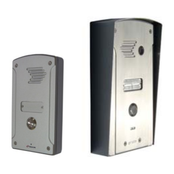
General:
The Doorphone unit is an intelligent telephone connected
to a telephone exchange, mounted on office entrance and
enables visitors to call to a predefined extension.
Person receiving a call from the door panel can speak with the visitor
and open the door from his telephone extension by pressing a
particular key.
Open the door from the inside is possible by pressing
a bypass pushbutton.
Features:
Easy installation, programming and
operating.
Controls a safety camera.
Programmable extension key to open door
Every extension can open the door by
pressing a key.
Anti vandal resistance.
Specifications:
Operating voltage: AC 12V 1000mA
Operating electric or magnetic lock. (normally
open or normally close)
Color: silver or bronze
Installation:
According to the door lock type,3 pins connector JM1 should be set
Desirable DOOR state when entering valid code
Close circuit (Normally open) for electric lock
Open circuit (Normally close) for magnetic lock
After installing the lock in the door frame. Route the following wirings to the Doorphone:
1. 2 wires from power supply.
2. 2 wires from the lock.
3. 2 wires from a telephone exchange free extension.
4. 2 wires from optional bypass pushbutton.
Using Phillips screw driver open 4 top cover's screws, carefully pull up the panel.
Using a screw driver, expose the 4 covered insulations bores and the round wirings bore.
Attach the base of the Doorphone to the wall, using a pencil mark the 4 fixing points.
Drill the 4 fixing points on the wall.
Route the wires through the round bore in the base of the Doorphone.
Using 4 screws install the base to the wall.
Verify the power supply is not connected to power source!
Connect the wires to circuit board terminals according to the circuit's labels, the attached
electrical diagram and the following instructions.
Connect: Power supply to the two 12VAC terminals.
To connect an electric lock: One wire from the lock to the RELAY terminal. The second wire
from the lock to one of 12VAC terminals. Short wire from the second 12VAC terminal to the
second RELAY terminal.
(the RELAY functions as a switch)
If you intend to install a bypass pushbutton, connect it between RMT terminal and the +V
terminal.
2 wires from telephone exchange free extension to LINE.
the polarity of the wires is non significant.
Tador Technologies
1
Doorphone User guide
Power failure resistance, keeps the
programmable values in nonvolatile memory.
Can be programmed from any extension.
Ability to control 2 entrance doors instead of
the camera.
optional bypass exit pushbutton
Opening time: 1-99 seconds
Size: under plaster 195X115X50mm (H*W*D)
On the wall 154X100X35mm (H*W*D)
Jumper JM1
Jumper on 2 left pins (default
state)
One Jumper on 2 right pins
Advertisement
Table of Contents

Related Manuals for Tador Doorphone


Summary of Contents for Tador Doorphone
-
Page 1: Specifications
Using a screw driver, expose the 4 covered insulations bores and the round wirings bore. Attach the base of the Doorphone to the wall, using a pencil mark the 4 fixing points. Drill the 4 fixing points on the wall. - Page 2 Type the new opening time value's 2 digits. (default 3 seconds) Type # to confirm. A confirmation beep sound will be heard. Conversation time: the amount of time you can speak with the Doorphone till it hangs up. If the value is smaller than 90 or equal, it represents seconds.
- Page 3 Tador Technologies Doorphone User guide Exit programming mode - type twice on the number sign ## or wait for 10 seconds.
- Page 4 Speaker volume adjustments The Doorphone unit leaves the manufacturer site adjusted. Sometimes because of the location (opened or closed space), acoustical problems occur. If the Doorphone’s speaker sound level is too high or low, gently rotate the internal SPK potentiometer. Operating...
- Page 5 Tador Technologies Doorphone User guide 2010...
Need help?
Do you have a question about the Doorphone and is the answer not in the manual?
Questions and answers