Table of Contents
Advertisement
Quick Links
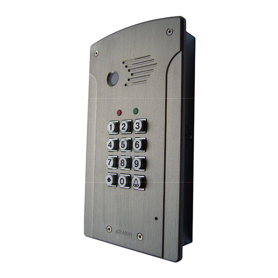
Tador Technologies CD-500 Installation guide
General:
The 5 wires encoder unit is an intercom system, serves as door
panel and encoder.
With this unit you can speak with the visitor who is waiting at
the door and open the electric lock from the intercom handset or
from the phone using Tador 5 wires adapter.
Authorized personnel can open the door by pressing
An access code.
By programming appropriately, each user can get an
individual access code.
The device includes an environment resistant and anti
vandal metal keyboard.
An optional bypass pushbutton enables easy internal
opening (the opening time is programmable)
Features:
Easy installation, programming and
operating.
up to 98 simultaneously different access
codes
Different and programmable opening time
from keyboard and bypass pushbutton
optional bypass exit pushbutton
Specifications:
Operating voltage: AC 12V 800mA
Operating electric or magnetic lock. (normally
open or normally close)
Color: silver or bronze
Installation:
J5 should be set accordingly to the door lock type (3 pins jumper)
Desirable RLY state when entering valid code
Close circuit (Normally open) for electric lock
Open circuit (Normally close) for magnetic lock
After installing the lock in the door frame. Route the following wires to the Intercom Encoder:
1. 2 wires from power supply.
2. 2 wires from the lock.
3. 5 wires from Intercom handset.
4. 2 wires from optional bypass pushbutton.
Using a Phillips screwdriver open the top cover, carefully pull up the panel.
Using a screw driver, expose the 4 covered insulations bores and the round wirings bore.
Attach the base of the Intercom Encoder to the wall, using a pencil mark the 4 fixing points.
Drill the 4 fixing points on the wall.
Route the wires through the round bore in the base of the Intercom Encoder.
Using 4 screws install the base to the wall.
Verify the power supply is not connected to power source!
Connect the wires to the circuit board terminal blocks according to the circuit's labels, the
attached electrical diagram and the following instructions.
Connect: Power supply to the two 12VAC terminals.
One wire from the lock to the RLY terminal. The second wire from the lock to one of the
12VAC terminal. Short wire from the second 12VAC terminal to the second RLY terminal.
(The RLY functions as a switch)
Power failure resistance, keeps the access
codes in nonvolatile memory
Environmental and anti vandal resistance.
Up to 1 million possible combination codes
Code length: 2-6 keys
Opening time: 1-9 seconds
Size: under plaster195X115X50mm (H*W*D)
On the wall 154X100X35mm (H*W*D)
Jumper J5
Jumper on 2 left pins (default state)
Jumper on 2 right pins
1
Surface
Flush/Surface
Mount
Mount
Advertisement
Table of Contents

Subscribe to Our Youtube Channel
Related Manuals for Tador CD-500


Summary of Contents for Tador CD-500
-
Page 1: Specifications
With this unit you can speak with the visitor who is waiting at the door and open the electric lock from the intercom handset or from the phone using Tador 5 wires adapter. Authorized personnel can open the door by pressing An access code. - Page 2 Tador Technologies CD-500 Installation guide Handset wiring Several common handsets could be assembled. Electric buzzer handset can not be assembled. Wiring of different handsets is detailed in the electrical drawing in page 4 and the following table: wire URMET Videx handset...
- Page 3 Tador Technologies CD-500 Installation guide Changing the programming code Enter the programming code: if not changed is: 123456 confirm with *, the green led will blink. now the following sequence should be entered: memory cell number 99 , new programming code ,and for verification again the memory cell number 99, the same new programming code.
- Page 4 Tador Technologies CD-500 Installation guide Microphone and speaker volume adjustments The Intercom Encoder unit leaves the manufacturer site adjusted. Sometimes because of the location (opened or closed space), acoustical problems occur. If the Encoder’s speaker sound level is too high or low, gently rotate the internal SP potentiometer.(clockwise to lower volume)
- Page 5 Tador Technologies CD-500 Installation guide Intercom Encoder Electrical drawing Microphone volume adjustment Speaker volume adjustment DEFAULT ר ס מ מ To avoid noises COM Normally and power ר ס מ מ open electric supply must lock be connected separately and directly...
Need help?
Do you have a question about the CD-500 and is the answer not in the manual?
Questions and answers