Table of Contents
Advertisement
Advertisement
Table of Contents

Related Manuals for Ossa TR280i


Summary of Contents for Ossa TR280i
-
Page 3: Introduction
At OSSA Motor we know that each motorcycle model is unique and We at OSSA Motor would like to thank you for purchasing one of our has its own features, which is why we dedicate so much time to the products. - Page 4 This manual has been put together with the OSSA TR280i current layout. However, OSSA Motor reserves the right to make changes to this layout without prior notification to consumers. In the event of...
-
Page 5: Safety
Safety Both your safety and the safety of others are very important when - Never drive if you have consumed alcohol or any type of substance riding a motorcycle. (medication, drugs) that might affect your driving capability. Some important advice for using your motorcycle correctly is detailed below. - Page 6 6 User manual...
-
Page 7: Table Of Contents
Contents Introduction Chain Important warning Tension adjustments Safety Lubrication of moving parts 40-42 Contents Tyres Technical specifications Pressure and condition Recommendations Control of crankcase oil Filling up and draining Section 1 - Components Brakes Location 12-14 Torque wrenches Multi-function box 15-22 Control pad Storage... -
Page 8: Technical Specifications
Technical specifications ENGINE Cubic capacity 272.2 cc Type Mono-cylindrical two inverted speeds with admission via slats directly to the sump Cooling system Liquid Diameter x stroke 70x60 mm Power supply EFI Kokusan Battery-less System Ignition CDI Kokusan digital magnetic steering Clutch Hydraulic clutch knob TRANSMISSION... - Page 9 Distance to the ground 340 mm Fuel tank capacity 2,6 litres Mass in service 64 kg OSSA Factory reserves the right to make modifications without prior notification. Kokusan, Marzocchi, OHlins are registered trademarks and their use is licensed. User manual User manual...
-
Page 10: Recommendations
Recommendations It is extremely important to follow the recommendations below in order to keep your motorcycle in full working order. - 12 hours of running-in is recommended to ensure that the engine works correctly and for a long-lasting time period. - It is important to run the engine for some minutes until it reaches the correct temperature to work correctly. -
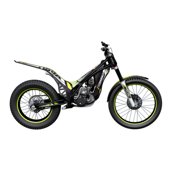
Page 11: Section 1 - Components
Section 1 - Components User manual User manual... - Page 12 Location of elements 1 Front mudguard 2 OSSA multi-function box 3 Fan and radiator 4 Cylinder 5 Sparkplug 6 Chain guide 7 Front tyre 8 Front fork stanchion 9 Front suspension bar 10 Gear lever 11 Chain 12 Chain slider...
- Page 13 Location of elements 15 Rear break caliper and anti-theft immobilizer 16 Exhaust 17 Kick-start pedal 18 Fuel tank 19 Rear brake disc 20 Swing arm 21 Rear break lever 22 Crankcase protector 23 Front break caliper 24 Front brake disc *Model without standardisation kit User manual 13 User manual...
-
Page 14: Control Pad
25 Front brake handle 26 Throttle grip 27 Throttle grip mechanism 28 Front brake pump 29 Right fork stanchion regulator 30 OSSA multi-function box 31 Left fork stanchion regulator 32 Clutch pump 33 Lights control pad 34 Clutch handle 35 Headlights... -
Page 15: Multi-Function Box
Multi-function box The OSSA TR280i multi-function box and the indicator lights next to it provide very useful information at all times. The multi-function box is a power box system with an LCD screen OSSA multifunction display controlled by a console with indicator lights, located in the centre of the handlebars. - Page 16 Multi-function box Technical features Technical features Functions Symbol Increasess Accuracy Current speed 4 - 399,9 Km/h o M/h 0,1 Km/h o M/h +/- 0,1% Tachometer 0 - 19999 rpm 10 rpm +/- 0,1% Tachometer bar 0 - 12000 rpm Variable +/- 0,1% Maximum speed 4 - 399,9 Km/h o M/h...
- Page 17 Multi-function Functions ODO: Mileage counter It records the distance or total accumulated mileage for the vehicle. RPM: Bar The data is stored in the memory, even when the device is switched off. Bar graph tachometer. The tachometer bar graph displays up to 12,000 rpm.
- Page 18 Multi-function Adjustment of the multi-function box settings After confirming each value, the multi-function box will move straight on to the next screen adjustment until the process is complete. If no button is pressed, the multi-function box will return to the initial screen after 15 seconds. Activation of the adjustment mode Select the speed unit To activate the adjustment...
- Page 19 Multi-function Time adjuster Adjustment of the revolution pulse Set the time by pressing (PPR) button 1 repeatedly. To move The indicator receives an to the next digit, press button electric pulse each time the 3. Confirm the selection by engine turns (PPR). Default pushing button 2.
- Page 20 Multi-function Temperature selector Warning temperature selector To select the unit of temperature, Note: either ºC or ºF, press button 1. This stage should only Confirm selection implemented for those vehicles pressing button 2. that have an optional temperatu- re sensor. When the motorcycle temperature exceeds the set value, the left-hand warning light comes on.
- Page 21 Multi-function Dangerous turn rate selector Setting the whole multi-function box to zero When the set rate is near to Press the RESET button by using a suitable object. The indicator will being reached, the right-hand boot again, excluding data that corresponds to total accumulated warning light will flash, indica- distance and time.
- Page 22 Multi-funcition Screen Options be brighter and will remain constant for 20 minutes after the vehicle has stopped. The multi-function box displays all information on three different screens. Sleep Mode While on, it is possible to see screens 1 or 2. Screen 3 is displayed for three seconds and then returns to screen 1.
-
Page 23: Control Pad
Control Pad Control Pad The control pad is located on the left handlebar, within reach of the thumb. This control pad can be used to control the lights, indica- tors, horn and engine stop. See the image with information about the control pad. 1 –... -
Page 24: Front Suspension
Front suspension The front suspension is made up of a fork that fixes the wheel and To regulate the extension, use the screw located on the right the front brake system in place. This fork is formed by the suspen- suspension bar (Fig. -
Page 25: Rear Suspension
Rear suspension The rear suspension is formed by a single shock absorber spring. The pre-charge of this spring can be adjusted by turning the toothed rings that dictate its direction. A special key is needed to adjust these toothed rings. The compression (C), extension (R) and spring pre-charge (see Fig.) are adjustable in the rear shock absorber. -
Page 26: Anti-Theft Immobilizer
Anti-theft immobilizer The TR280i has an immobilisation system for protection against IMPORTANT: this key has a code which is needed for theft. making duplicate copies of the key. This code should be written down in the indicated space on the registration This system consists of a lock situated in the area of the brake discs page and series number of this manual. - Page 27 Kick start pedal The kick-start pedal is part of the mechanism that is used to kick If the motorcycle has been inactive for a long period of start the motorcycle mechanically. time, its recommended that the kick-start pedal is activa- ted gently 3 or 4 times, without actually kick-starting the Before kick starting the motorcycle check that it is at brake point motorcycle.
-
Page 28: Fuel Tank
Fuel tank The engine of this motorcycle uses a mixture of unleaded petrol and 2T oil, 100% synthetic in a 0.9 proportion. The fuel tank forms a structural part of the chassis and is located on the front inside part. To fill up with petrol, open the fuel tank lid, situated on the upper part, by unscrewing in an anti-clockwise direction. - Page 29 Upper Section To access different parts of the motorcycle or the motorcycle’s electrical system the upper section should be removed. This section is made up of 2 parts that are screwed onto the chassis and fitted together. The first part of this section is located on the front above the fuel tank.
- Page 30 User manual 30 User manual...
-
Page 31: Section 2 - Maintenance And Basic Operations
Section 2 – Maintenance and basic operations User manual User manual... - Page 32 Maintenance grid – Engine Item Replace / Change Grease / lubricate Check / Inspect Adjust Clean When damaged Air filter Each use Each use Each wash 30 Hours 60 horas Transmission oil Refrigerant Each use Each year Each use 60 Hours 15 Hours Sparkplug 30 Hours...
- Page 33 Maintenance grid – Cycle Item Replace / Change Grease / lubricate Check / Inspect Adjust Clean Rear shock absorber Each year Every 2 years Front suspension Each year When necessary Every 2 years 60 Hours Front suspension lubricant Brakes Each use When necessary When damaged Swing arm and linkage arms...
-
Page 34: Adjustments To The Motorcycle Controls
Adjustments to the motorcycle controls The clutch lever is located on the left handlebar grip and is used to activate the clutch mechanism to change gear. The front brake lever is located on the right handlebar grip and is used to activate the brake caliper of the front brake. min. -
Page 35: Electrical Connections
Electrical connections Check the condition of the motorcycle’s electrical connections in order to ensure they are maintained in good working order. As can be seen in the illustration on the right, these are located at the bottom of the air- lter housing, between the steering bar and the front headlight, and in the fuel system apparatus. - Page 36 Simplified diagram of the lights Esquema simpli cado instalación de luces Manual de usuario 36 User manual...
- Page 37 Esquema simpli cado instalación de inyección Simplified diagram of the injection installations Manual de usuario 37 User manual...
- Page 38 Air lter Air lter. Cleaning and maintenance The air lter should be controlled periodically. Detach the upper section of the motorcycle to reach the lter box. Remove the sensor on the lter base and the clasp. Then remove the lter, according to the illustration.
-
Page 39: Radiator
Radiator The radiator contains the engine refrigerant. To fill up with or add To fill the radiator, special refrigerant should be used -30ºC. refrigerant to the radiator, locate the tank lid. To locate this lid, detach the air filter lid (see page 36 - Air Filter). Once the filter lid is detached, the radiator lid is visible. -
Page 40: Sparkplug
Sparkplug To access the sparkplug detach the upper section of the motorcy- Observe the distance between the electrode and the cle (see page 29). Once the upper cover has been removed, the arch. This distance should be 0.7 mm. motorcycle’s electrical system can be accessed. Carefully but firmly, pull away the hood that provides a current, leaving the upper part of the sparkplug exposed. -
Page 41: Tension Adjustments
Chain – tension adjustments The transmission chain transmits the engine’s movement to the rear wheel. To ensure that is works correctly, it should be checked. The axle has easily adjustable eccentrics for tensing the chain and centring the wheel. The chain hook should be positioned in an opposite direction to the gear, as can be seen in the photo. -
Page 42: Lubrication Of Moving Parts
Lubrication of moving parts Cleaning the motorcycle and lubricating the mobile parts will help protect the motorcycle and guarantee that it works better. If using a high pressure hose to clean the motorcycle, bear in mind that the water pressure might rip off the stickers or cause damage to the motorcycle. - Page 43 Lubrication of moving parts The chain drive should always be well lubricated. The chain must be lubricated using special oil for chain Check it each time the motorcycle is used and apply drives. lubrication when necessary. Gear change lever joints Rear brake pedal joints and bearings Chain drive User manual...
- Page 44 Lubrication of moving parts Footrest bracket and springs Chain drive and tension adjuster springs Gas handle (right grip) Engine kick-start pedal joints User manual 44 User manual...
-
Page 45: Tyres
Tyres Pressure and condition To ensure that the motorcycle works correctly, it’s very important to check the tyre pressure and that the wheels are in good working condition before each use. Using tyres that are in a good condition will mean that the motorcycle is capable of performing to the best of its ability. - Page 46 Checking the crankcase oil IMPORTANT: Clean the plug and change the sealing washer each Filling and draining the crankcase time the oil is changed. Crankcase oil is used for lubricating the change pedal and the clutch. Check the oil level with the indicator located on the lower The crankcase has a 350cc oil capacity.
-
Page 47: Brakes
Brakes The brakes permit precise and controlled trial riding. It is necessary to check them in order to ensure that they work correctly. Wear on the front and rear brake pads must be periodically controlled so that the brakes work e ectively. -
Page 48: Torque Wrenches
Torque wrenches These grids show the pressure that should be used to tighten parts. CHASSIS MOTOR Part Part Front wheel axle 40 - 50 Sparkplug Clutch xing Swing arm xing to chassis 70 - 80 7 - 8 Upper shock absorber xing 40 - 50 Cylinder clasp xing 7 - 8... -
Page 49: Storage
Storage Storage Starting the motorcycle again If the motorcycle is to be stored for a long period of time, the To start up the motorcycle after a period of inactivity, the following following procedure should be followed to ensure that it is stored procedure should be followed: correctly. -
Page 50: Troubleshooting
Troubleshooting PROBLEM POSSIBLE CAUSE POSSIBLE SOLUTION The engine won’t start - Long period of engine inactivity - Change the old petrol for new petrol - Sparkplug dirty or wet - Dry / clean or change the sparkplug - General fuse damaged - Change general fuse - Bad electrical connection - Check electrical connections and position correctly... - Page 51 Troubleshooting PROBLEM POSSIBLE CAUSE POSSIBLE SOLUTION The motorcycle is unstable - Wire makes it difficult for the handlebar - Move wire or loosen it a bit to turn - Loosen the steer axle screw - Steer axle screw is very tight - Steering bearings are damaged or with - Replace steering bearings wear...
- Page 52 Troubleshooting PROBLEM POSSIBLE CAUSE POSSIBLE SOLUTION The shock absorption is too soft - Too little oil in front fork - Add oil to the fork until it reaches a sufficient level - Front fork oil not sufficiently viscous - Drain fork oil and fill up with suitably viscous oil - Front fork bent - Change the front fork.
- Page 53 Troubleshooting PROBLEM POSSIBLE CAUSE POSSIBLE SOLUTION The motorcycle makes abnormal - Cylinder damaged - Replace the damaged cylinder noises - Supports, screws or nuts are not properly - Check and adjust using suitable torque wrench fastened - Tyres wear, swing arm or its needle - Change worn parts for new parts bearings wear - Wheel rim not centred...
- Page 54 Troubleshooting PROBLEM POSSIBLE CAUSE POSSIBLE SOLUTION The motorcycle tends to lean to one - Bent chassis - Change chassis. Go to specialist mechanic side - Steering badly adjusted - Adjust steering. Go to specialist mechanic - Steer axle bent - Change steering axle. Go to specialist mechanic - Front fork bent - Change front fork - Wheels badly centred...
- Page 55 Elementos de homologación Manual de usuario User manual...
- Page 56 Standardisation components Your Ossa TR280i is standardised in compliance with UE regulations. It adheres to all standardisation requisites. EURO-3 The obligatory elements to be registered for driving on public roads and for passing the vehicle’s MOT are listed below. The elements to be registered among others are identified with a specific mark and registration.
-
Page 57: User Manual User Manual 7
8.Manufacturer’s plate Each of the registered elements should be part of the vehicle. In the event of breakages, loss or bad functioning, it is recommended that you go to an official OSSA mechanic to remedy the problem. User manual User manual... - Page 58 Standardisation components Element Standardisation identification 1. Front headlight 11/12-e9*97/24*97/24/*4367*00 Front position lamp R55.00.14839 Driving beam R113.00.14839 Passing Beam R113.00.14839 2. Front indicators 11001200e94367 3. Rear indicators 11001200e94367 4. Rear pilot e13*50 R00*50R00*12448*00 5. License plate support 6. Reflector IA.E9.02.01269 7. Mirror L-e9*80/780*80/780*0143*01 8.
- Page 59 Standardisation components Manufacturer’s plate Serial number User manual User manual...
- Page 60 Standardisation components The key number can be found under the red disk. Remove the disk to see the number. Engine number Key number User manual 60 User manual...
- Page 61 Warranty User manual User manual...
- Page 62 The warranty is associated to the product indicated in the “CERTIFICATE OF DELIVERY AND INSPECTION”, which shall be filed out by autho- rised staff in OSSA FACTORY, SL (hereinafter referred to as OSSA). It is valid for those countries indicated on page 33. The warranty is only applicable to motorcycles that have been initially imported via the official OSSA importer for your country, meeting all the regulatory require- ments and authorisations of each country.
- Page 63 Warranty The repair is disproportionate when it is uneconomic, or when the reparation is more expensive than the value of the product. If this occurs, the purchaser can choose between a price reduction or contract resolution. Resolution is not permitted when the non-compliance is insignifi- cant.
- Page 64 User manual 64 User manual...
- Page 65 Warranty Exceptions to the warranty User manual User manual...
- Page 66 Warranty User manual 66 User manual...
- Page 67 Warranty User manual User manual...
- Page 68 Procedure for obtaining repairs under warranty If your motorcycle needs a repair to be carried out under warranty, it should be taken to your official OSSA dealer where the repair will be made (YOU ARE RESPONSIBLE FOR THE TRANSPORT COSTS TO AND FROM THE DEALER).
- Page 69 Final information User manual User manual...
- Page 70 70 User manual...
- Page 71 User manual...
Need help?
Do you have a question about the TR280i and is the answer not in the manual?
Questions and answers