Table of Contents
Advertisement
Advertisement
Table of Contents

Related Manuals for Quickie Xenon


Summary of Contents for Quickie Xenon
- Page 1 Directions for use 690675.01 Xenon...
- Page 2 For visually impaired people, you will find information on our website (www.SunriseMedical.com).
-
Page 3: Foreword
Foreword Dear Customer, Wheelchairs are exclusively for a user who is unable to walk or has limited mobility, for their own personal use, We are very pleased that you have decided in favour of a when self-propelling and being moved by a third party high-quality SUNRISE MEDICAL product. -
Page 4: Table Of Contents
Table of Contents Definitions Foreword 3.1 Definitions of words used in this manual Area of Application. Word Definition Table of Contents Definitions Advice to the user of Potential Risk DANGER! of serious injury or death if the General Safety Notes and Driving Limits Guarantee advice is not followed Wheelchair components... -
Page 5: General Safety Notes And Driving Limits 5 Danger
General Safety Notes and Driving Limits WARNINGS! WARNINGS! The construction of this wheelchair, as well as the • Maximum weight limit: 125 kg. Please note the technology used, are designed to give the maximum level weight information for lighter weight options, of safety. - Page 6 DANGER! DANGER! The wheel locks are not intended to brake your • In particular when using lightweight metal handrims, wheelchair whilst it is moving. They are only there to fingers will easily become hot when braking from a ensure that your wheelchair does not begin rolling away. high speed or on long inclines.
-
Page 7: Guarantee
Guarantee Guarantee 6) Consumable parts are normally excluded from the THIS DOES NOT AFFECT YOUR LEGAL RIGHTS IN guarantee, except in the case that premature wear of the ANY WAY. part is the direct result of a manufacturing fault. These parts include, amongst others, upholstery, tyres, inner Guarantee conditions tubes and similar parts. -
Page 8: Wheelchair Components
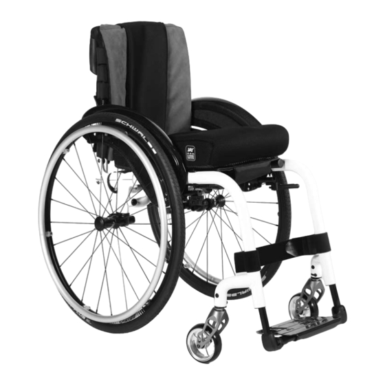
Wheelchair components Push handles Back sling Sideguard Seat sling Footrest Castors Footboard Fork Quick-release axle Wheel locks Handrim Rear wheel Folding bracket Fig. B... -
Page 9: Handling
Handling Fig. 1 Folding up First remove the seat cushion from the wheelchair and flip up the (platform) footplate. Take hold of the sling or the seat tubes (Fig. 1) in the middle, from the back, and pull it upwards until the folding bracket (Fig. 2) clicks into place. -
Page 10: Quick Release Wheels
Quick Release Wheels Fig. 7 Quick-release axles on rear wheel The rear wheels are equipped with quick-release axles. The wheels can then be fitted or removed without using tools. To remove a wheel, simply depress the quick- release button on the axle and pull the wheel off the axle. (Fig. -
Page 11: Drum Brakes
Brake Lever Extension Fig. 11 The longer lever helps to minimise the effort needed to set the wheel locks. The brake lever extension is screwed to the brakes. By raising this, it can be flipped forward. (Fig. 11). CAUTION! Mounting the wheel lock too close toward the wheel will result in a higher effort to operate. - Page 12 Footrests Fig. 14 Various footboards are available on the Xenon. These can flipped up to make it easier to transfer to/from the chair. They are described individually. Lower leg length By undoing the clamp screw (Fig.14), you can adjust the lower leg length.
-
Page 13: Footboard
Width adjustment of footrests Fig. 18 If the footrest width needs to be adjusted, please undo the screw (1), set the desired width, by positioning 1, 2 or 3 spacers (2) from outer to the inner side and then refit the screws, (Fig.18). -
Page 14: Options - Seat
Options – Seat Fig. 22 Seat sling Use the Velcro straps under the sling to tighten/loosen the seat sling. Adjusting the seat height To change the seat height, please release the Allen screws (1) with an Allen key. Take the axle bracket (2) out of the axle stem (3) and remove or add the spacer (4). - Page 15 Rotate the axle bracket (Standard) Fig. 26 Using the quick-release axles, take the wheels out of the angle adapter. Undo the screws (1) and remove the axle brackets (2) on both sides of the wheelchair. Rotate the axle bracket by 180°...
-
Page 16: Options - Castors
Options - Castors Fig. 30 Setting the Castor, Castor adapter & Castor fork +8° - 8° If the wheelchair veers slightly to the right or left, or the castors flutter, it may be caused by one or more of the following: •... -
Page 17: Options - Backrests
Options - Backrests Fig. 32 To adjust the back angle, please undo the Allen screw (1) and remove it. Set the desired position and then refit the screw in this position and tighten it to the given torque (Fig. 32). Folding backrest To make it easier to transport the wheelchair, the top half of the backrest can folded down. - Page 18 Options - Wheel Alignment Fig. 30 Fig. 36 Adjusting the wheel alignment NOTE: To achieve the very best movement, the rear wheels must be adjusted to their optimum position, which means correctly adjusting the wheel alignment. To do this, measure the distance between both wheels front and rear to ensure that they are parallel to one another.
-
Page 19: Options - Side-Guards
Options - Side-guards Fig. 38 1. Fitting a. Push the outer armrest rails down into the receiver which is mounted on the wheelchair frame. b. The armrest will automatically lock into place. 2. Height adjustment a. Turn the release lever for height adjustment (2) to the second stop point. -
Page 20: Options - Push Handles
Options - Side-guards (continued) Fig. 42 Side-guard with clothes protector The clothes protector prevents clothes getting dirty from spray water, (Fig.42). You can set the position in relation to the rear wheel by moving the side-guard. To do this, remove the screws (1 and 2). After setting to the desired position, re-tighten the screws (see the page on torque). -
Page 21: Options - Crutch Holder
Options - Crutch Holder Fig. 45 Crutch holder This device permits crutches to be transported directly on the wheelchair. It has a Velcro loop to fasten crutches or other aids. WARNING! Never try to use or remove the crutches or other aids while moving. -
Page 22: Options - Stabilising Bar
Options - Stabilising Bar Fig. 48 Folding stabilising bar This bar is used to stabilise the backrest. To be able to fold the wheelchair, the release lever must be pushed inwards (Fig. 48) or released and the stabilising must be flipped downwards. -
Page 23: Options - Pelvic Restraint Belt
Options - Pelvic Restraint Belt Fig. 54 WARNINGS! • Before using the wheelchair make sure that the pelvic restraint belt is fitted. • The pelvic restraint belt must be checked on a daily basis to ensure it is free from any obstruction or adverse wear. -
Page 24: Options - Pelvic Restraint Belt Continued
Options - Pelvic Restraint Belt continued Fig. 59 When fastened check space between the pelvic restraint belt and user. When correctly adjusted it should not be possible to insert more than the flat of the hand between the pelvic restraint belt and the user, (Fig. 59). The pelvic restraint belt should be fixed so that the belt sits at an angle of 45 degrees across the user's pelvis. -
Page 25: Daily Checks
Maintenance and Care Daily Checks CAUTION! • Check the tyre pressure every 4 weeks. Check all tyres for wear and damage. As the user, you are the first person to notice any possible • Check the brakes approximately every 4 defects. -
Page 26: Troubleshooting
Wheelchair squeaks and rattles Maintenance and Care continued • Check to make sure all bolts are secure; tighten if necessary (see the section on torque) Hygiene measures when being re-used: • Apply small amount of lubrication to spots where movable parts come in contact with one another Prior to the wheelchair being re-used, it must be carefully prepared. -
Page 27: Nameplate
Nameplate Technical Specifications The nameplate is located on either the cross-tube Overall width: assembly or the transverse frame tube, as well as on a With standard wheels including hand rims, close mount: label in the owner’s manual. The nameplate indicates the •... - Page 28 Technical Specifications continued Maximum weight limit: Xenon up to a load of 125 kg Seat heights: The choice of frames, forks and castors as well as the size of the rear wheel (610mm (24")), (635mm (25")); determines what seat heights are possible.
- Page 29 Technical Specifications continued Castor Fork Type of frame Front seat height Rear seat height in mm in mm 430 - 400 440 - 400 450 - 390 98 mm x 32 mm 470 - 380 high 480 - 380 490 - 380 76mm (3") 440 - 400 450 - 390...
- Page 30 Technical Specifications continued Castor Fork Type of frame Front seat height Rear seat height in mm in mm 460 - 380 470 - 380 98 mm x 32 mm 500 - 380 high 510 - 390 460 - 380 470 - 380 480 - 380 111 mm x 32 mm 500 - 380...
- Page 31 Technical Specifications continued Castor Fork Type of frame Front seat height Rear seat height 480 - 380 490 - 380 FROGLEG 500 - 380 76mm (3") 520 - 400 530 - 410 high 540 - 420 490 - 380 500 - 380 FROGLEG 510 - 390 102mm (4")
-
Page 32: Torque Settings
Torque Settings NOTE: If no specific torque information is given, the generic torque value for M6 screws is 7.0 Nm 7 Nm 7 Nm 7 Nm 7 Nm 7 Nm 7 Nm... - Page 33 NOTES Dealer signature and stamp...
- Page 34 NOTES Dealer signature and stamp...
- Page 35 NOTES Dealer signature and stamp...
- Page 36 Sunrise Medical GmbH & Co. KG 69254 Malsch/Heidelberg Germany Tel.: +49 (0) 7253/980-0 Fax: +49 (0) 7253/980-111 www.sunrisemedical.com Sunrise Medical Limited High Street Wollaston West Midlands DY8 4PS England Tel.: +44 (0) 1384446688 www.sunrisemedical.com Sunrise Medical S.L. Polígono Bakiola, 41 48498 Arrankudiaga –...
Need help?
Do you have a question about the Xenon and is the answer not in the manual?
Questions and answers