Table of Contents
Advertisement
Quick Links
Advertisement
Table of Contents

Subscribe to Our Youtube Channel
Related Manuals for Blata Ultima


Summary of Contents for Blata Ultima
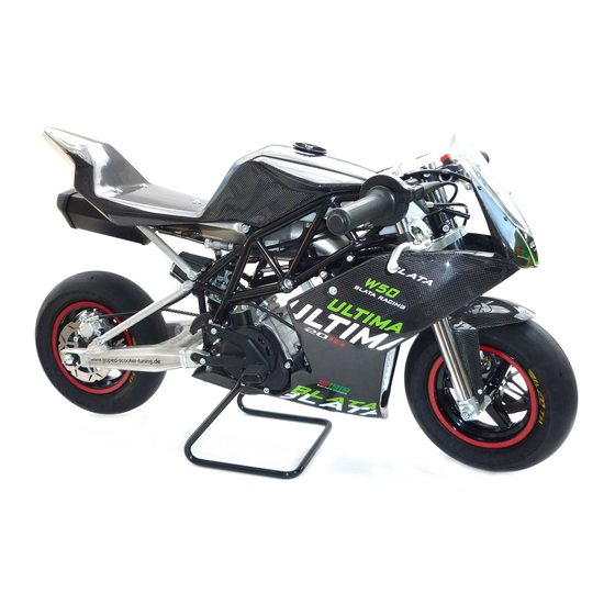
- Page 1 User manual for the minibike Blata Ultima EN ver. 02-2009/12/11 www.BLATA.com...
- Page 2 SAFETY WARNING Pay extra attention when performing maintenance and service of the machine and maintain the safety warning and instructions stated below! Before putting the minibike into operation, familiarize yourself carefully with instructions about its proper use and maintain them in the interest of your safety and also the safety of others.
- Page 3 Make sure that it is stored near the machine so it is constantly available. The complete delivery of the minibike Blata Ultima is composed of: - Do not, under any circumstances, use the machine in any other way than is descri- - Transport packing - carton box bed in this manual.
-
Page 4: Table Of Contents
Declaration about noise Putting out of operation The Minibike - Ultima is designated for driving on enclosed tracks on flat and dust free sur- Storage faces. Adults and also children can ride on it. Children can only ride on it under the supervi- Repeat putting into operation sion of a responsible adult. -
Page 5: Technical Data
TECHNICAL DATA engine (Blata 2T) RM14 cooling water water displacement (cm 39,8 39,8 39,8 39,8 49,7 power (kW) 10,7 torque (Nm) 10,7 carburetor DELL´ORTO PHVA 14 DELL´ORTO PHVA 14 DELL´ORTO PHVA 14 DELL´ORTO PHVB 19 DELL´ORTO PHVB 19 ignition contactless... -
Page 6: Preparation Of The Minibike For Operation
PREPARATION OF THE MINIBIKE FOR OPERATION IMPORTANT WARNING The Minibike is delivered packaged in a carton box with folded handlebars and brake Turn the engine off immediately if the level of the cooling fluid in the leveling reservoir levers. After unpacking, set the handlebars to the functioning position which suits increases during operation! Check the drive of the cooling pump and the cooling system you best. -
Page 7: Regular Maintenance
REGULAR MAINTENANCE ADJUSTMENT OF ENGINE BOTTOM BRACKET Regular performing of maintenance is one of the best methods of contributing to the 1. Remove the engine braket on cylinder fig. 5 prolonging of the service life of the machine, ride safety and the lowering of expenses. head and keep the engine on the bot- tom bracket only. -
Page 8: Bleeding The Hydraulic Brakes
BLEEDING THE HYDRAULIC BRAKES important warning: fig. 8 - The brakes are one of the most important components of your minibike. We recom- mend to leave the maintenance and the adjustment of the hydraulic brakes up to a qualified mechanic. - Follow the safety warning. -
Page 9: Replacement Of The Brake Pads Of The Hydraulic Brakes
REPLACEMENT OF THE BRAKE PADS OF THE HYDRAULIC BRAKES REPLACEMENT OF THE FRONT BRAKE PADS OF THE MECHANICAL BRAKES, fig. 30 Loosen the lock ring of the bolt of the brake pads. Unscrew the bolt of the brake pads. Remove the worn pads from the caliper together with the metal spring of the brake First screw in the adjustment mechanism of the right brake lever (122.002.00) to the pads. -
Page 10: Removal And Mounting Of The Front Wheel
REMOVAL AND MOUNTING OF THE FRONT WHEEL REMOVAL AND MOUNTING OF THE REAR WHEEL Unscrew the nut of the front wheel axle and slide the axle out. Remove the wheel Loosen the nut of the rear wheel axle. Loosen the check nuts and the adjustment bolts carefully from the fork in the downward and forward direction. -
Page 11: Change Of The Geometry Of The Chassis
CHANGE OF THE GEOMETRY OF THE CHASSIS The BLATA SET-UP SYSTEM includes three areas of the minibike, in which it is possi- Carefully tap in the required steering plate into one end of the steering neck. Insert the ble to significantly change the geometry of the chassis. This is the change of the spacer tube and tap in the second plate from the other side of the steering neck. -
Page 12: Change Of The Seat Height
The adjustment is performed by the replacement of the spacer rollers of various leng- ths on the disassembled supports of the rear fork. We follow the following procedure fig. 17 during the replacement. Remove both the supports of the rear fork from the minibike. Totally unscrew the securing bolts from the supports. -
Page 13: Replacement Of The Centrifugal Clutch Levers
REPLACEMENT OF THE CENTRIFUGAL CLUTCH LEVERS REMOVAL AND MOUNTING OF THE AIR FILTER Loosen the chain, remove the bearing housing and take the chain off the pinion. Uns- During the removal of the filter, first loosen the screws of the strap, which is securing crew the 3 bolts holding the clutch housing together with the clutch basket and remove the rubber extension of the filter on the carburetor. -
Page 14: Maintenance Of The Cooling System
MAINTENANCE OF THE COOLING SYSTEM TIGHTENING TORQUES 1. Filling up with fluid: tightening use - MOTOR number fig. securing Remove the top cowling. Place the minibike so that the front wheel is 30 cm higher torque (Nm) Cylinder head, water – M6 920.015.01 35, 36 than the rear wheel, see fig. -
Page 15: Composite Materials
The company Blata is the first among minibike manufacturers to bring modern com- The operational conditions during measuring are contained in the Report about noise posite materials. The Minibike Ultima uses carbon not only as a fashion supplement, measuring which is stored at the manufacturer. -
Page 16: Putting Out Of Operation
TECHNICAL SERVICE Contact your dealer in the case of any unclarity with this manual or with the mainte- nance and service of your minibike. The updated list of the dealers is stated on the Internet pages of the manufacturer www.BLATA.com. -
Page 17: Hydraulic Brakes
HYDRAULIC BRAKES HYDRAULIC BRAKE LEVER fig. 26 fig. 28 342.220.00 - Brake lever left (hydraulic brake) front brake 342.221.00 - Brake lever right (hydraulic brake) 342.222.00 - Brake lever universal 342.225.00 – Brake piston set 342.225.00 rear brake 342.227.00 - Set of O-ring seals: 342.222.00 971.044.00 - O-ring 2x1 (2 pc) 971.049.00 - O-ring 4x1 (1 pc) -
Page 18: Mechanical Front Brake
MECHANICAL FRONT BRAKE MECHANICAL BRAKES HOLDER fig. 30 fig. 32 Front mechanical brake holder - 262.112.00 Rear mechanical brake holder - 262.216.00 MECHANICAL REAR BRAKE ENGINE - COMPLETE fig. 31 fig. 33... -
Page 19: Engine R40, Rm9, Rm14
ENGINE R40, RM9, RM14 fig. 34 260.300.00 - Engine R40 set 260.400.00 - Engine RM9 260.500.00 - Engine RM14... -
Page 20: Engine W40
ENGINE W40 fig. 35 260.200.00 - Motor W40... -
Page 21: Engine W50
ENGINE W50 fig. 36 260.001.00 - Motor W50... -
Page 22: Rotor
ROTOR CLUTCH CASE COMPLETE fig. 37 fig. 39 330.018.20 - KIT 330.085.60 - KIT 914.008.01 - KIT 338.002.00 330.085.50 - SERIE 914.001.01 - SERIE 330.018.01 - SERIE 330.085.20 - KIT 330.028.00 - SERIE 960.012.00 330.029.00 950.009.00 330.028.20 - KIT 330.028.01 - SERIE 960.009.01 950.008.00 330.024.40 - KIT... -
Page 23: Diaphragm - Complete
DIAPHRAGM COMPLETE HEAD BLAST - WATER COOLING fig. 41 fig. 43 330.073.42 - W40 260.080.00 - W50 330.058.01 330.071.22 - W40 310.040.00 330.051.00 260.081.00 - W50 330.120.00 EXHAUST R40 (RM9, RM14) HEAD BLAST - AIR COOLING fig. 42 obr. 44 150.073.30 ... -
Page 24: Front Fork
FRONT FORK FRONT WHEEL fig. 45 fig. 46 263.050.00 - Disk front lightweight 263.053.00 - Disk front standard 335.033.02 335.033.02 REAR WHEEL fig. 47 Chains 517.001.24 - MINI 517.001.46 - MIDI 263.051.00 - Disk rear lightweight 263.052.00 - Disk rear standard... -
Page 25: Frame
FRAME TANK - COMPLETE fig. 48 fig. 49 269.052.00 RADIATOR fig. 50 319.001.01 radiator set - 269.100.00 - 269.130.00 (1x) - 269.110.00 (1x) - 269.131.00 (1x) - 269.105.00 (1x) - 269.106.00 (1x) - 319.012.03 (2x) - 269.120.00 (3x) set of hoses + clips - 269.050.00 - 319.012.01 (1x) - 319.012.02 (1x) - 319.012.03 (5x) -
Page 26: Exhaust - Complete W40
260.631.00 260.700.02 Exhaust W50 set - carbon end piece silencer nut 260.603.00 260.700.03 Exhaust W50 set - carbon set bolt M3 DIN 913 916.179.02 sticker www.blata.com size A 269.304.00 fig. 54 ord. no. reg. no. name amount 260.151.00 exhaust elbow 2TW50W40 260.160.00... -
Page 27: Cowling
COWLING fig. 55... -
Page 28: Cowling Table
COWLING TABLE reg. number name reg. number name amount 264.300.B0 front whole - cowling complete, blue 264.050.0B whole - cowling complete set, blue 264.100.B0 saddle - cowling complete, blue 264.001.B0 front fender glass fiber - blue 264.300.L0 front whole - cowling complete, black 264.050.0L whole - cowling complete set, black 264.100.L0... - Page 29 Thank you for the favor which you have shown to our machine BLATA ULTIMA and we wish you many true racing experiences on the track. the company BLATA The company BLATA reserves the right to change the technical design, text and sha- pe of the vehicle.
- Page 30 BLATA s.r.o. contact to dealer Pražská 9 678 01 Blansko Czech Republic tel.: +420 516 522 111 fax: +420 516 522 100 e-mail: recepce@blata.com The electronic version of this brochure can be found at www.blata.cz. © COPYRIGHT BLATA 2009...
Need help?
Do you have a question about the Ultima and is the answer not in the manual?
Questions and answers