Table of Contents
Advertisement
Quick Links
Advertisement
Table of Contents

Related Manuals for Cleanburn Skagen


Summary of Contents for Cleanburn Skagen
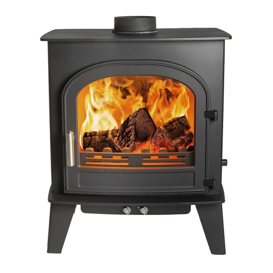
- Page 1 Skagen Skagen Cleanburn Stove Cleanburn Stove JINHCE08 revC 26/10/11...
- Page 2 Installation & Operating Instructions Technical Specification Appliance Mass 125 kg Total Efficiency 79.0 % Nominal Heat Output 6.0 kW Mean CO Emission (@13% O 0.16 % Mean Flue Gas Temperature 280 °C 5.0 g/s Flue Gas Mass Flow This appliance is not for use in shared flue This appliance is suitable for intermittent burning JINHCE08 revB 03/10/11...
-
Page 3: Table Of Contents
T able of Contents General Guidance ......................2 Competent Persons Scheme ................ 2 CO Alarms ....................2 Health & Safety Precautions ............... 2 Handling ...................... 2 Fire Cement ....................2 Asbestos ...................... 3 Metal Parts ....................3 Modification ....................3 Safety .......................... - Page 4 Lighting the Stove ..................13 Reduced Combustion ................13 Recommended Fuels ................. 14 General Maintenance..................... 15 Baffle ......................15 Stove Body ....................15 Glass Panel ....................15 Firebricks ....................15 Door Catch ....................15 Rope ......................16 Chimney and Flue ways ................16 Periods of Prolonged Non-Use ..............
-
Page 5: General Guidance
British Standards BS 8303 and BS EN 15287 1. Competent Persons Scheme Cleanburn recommend that this stove is installed by a member of an accredited competent persons scheme e.g. HETAS. If the installer is not a member of a competent persons scheme, it is a legal requirement to notify your local building control body in advance of any work starting. -
Page 6: Asbestos
Asbestos This stove contains no asbestos. If there is a possibility of disturbing any asbestos in the course of installation then please seek specialist guidance and use appropriate protective equipment. MetalParts When installing or servicing this stove, care should be taken to avoid the possibility of personal injury. Modification No unauthorized modification of this appliance should be carried out. -
Page 7: Coalarm
Adverse weather – In a small number of installations, occasional local weather conditions (e.g. wind from a particular direction) may cause downdraught in the flue and cause the stove to emit fumes. In these circumstances, the stove should not be used. A professional flue installer will be able to advise on solutions to this problem (e.g. -
Page 8: Assembly Instructions
Assembly Instructions Instructions Removal of Heat Shield To remove the heat shield, remove the button To remove the heat shield, remove the button head screw and then flex the heat shield by pulling the heat shield towards you until flex the heat shield by pulling the heat shield towards you until the right hand edge clears the stove body hand edge clears the stove body and pops out. -
Page 9: Blanking Plate
Blanking Plate Fit the Flue Gasket and Blanking Plate on the remaining free outlet Fit the Flue Gasket and Blanking Plate on the remaining free outlet. Secure it, using the M6 nuts and studs. studs. Heat Shield Knockout Rear Flue Pipe Installation For rear flue installations, the knock the knockout in the rear heat shield must be removed. -
Page 10: Removal Of Internal Components
Removal of Internal Components Removal of Internal Components The Fire Bricks, in this appliance, are factory fit The Fire Bricks, in this appliance, are factory fitted. The following set of diagrams of diagrams show the removal sequence that you will need to employ when servicing your sequence that you will need to employ when servicing your stove. -
Page 11: Rear Brick
Rear Brick Pull the top edge of Pull the top edge of each Rear Brick forward and lift the brick out of the Rear Brick forward and lift the brick out of the Stove. Stove. Baffle / Throat Plate Fitting To install the Baffle, slide the left hand end of the Baffle up, hand end of the Baffle up, and over the support. -
Page 12: Installation Instructions
Installation Instructions Chimney The chimney height and the position of the chimney terminal should conform to Building Regulations. Check that the chimney is in good condition, dry, free from cracks and obstructions. The diameter of the flue should not be less than 150mm and not more than 200mm. If any of these requirements are not met, the chimney should be lined by a suitable method. -
Page 13: Flue Draught
Flue Draught If the draught exceeds the recommended maximum, a draught stabiliser must be fitted so that the rate of burning can be controlled and to prevent over firing. If the reading is less than the recommended minimum then the performance of the appliance will be compromised. The flue draught should be checked under fire at high output. -
Page 14: Recessed Appliance
Recessed Appliance The stove can be recessed into a suitably sized fireplace The stove can be recessed into a suitably sized fireplace with a minimum 50mm clearance all around with a minimum 50mm clearance all around, but we recommend that a free air gap of 150 mm is left around the sides and top of the stove and at least we recommend that a free air gap of 150 mm is left around the sides and top of the stove and at least we recommend that a free air gap of 150 mm is left around the sides and top of the stove and at least 50mm at the back of the stove to obtain maximum heat output and for access to the rear of the stove. -
Page 15: Operating Instructions
Operating Instructions This appliance is not suitable for use in a shared flue This appliance should not be operated with the doors open Aerosol Sprays Do not use an aerosol spray on or near the stove when it is alight. Air Controls This stove has been designed to burn far more efficiently than a traditional stove, with the obvious notable feature of clean glass. -
Page 16: Riddling Grate
Riddling Grate Your Cleanburn stove is fitted with a locomotive type grate. So that de ashing can be carried out cleanly and easily, it is riddled from the outside of the stove with the doors closed. To burn wood, push the operating tool up and away from you. -
Page 17: Recommended Fuels
Recommended Fuels Cleanburn recommend that wood logs are burnt in this appliance. Burn only dry, well seasoned wood, which should have been cut, split and stacked for at least 12 months, with free air movement around the sides of the stack to enable it to dry out. -
Page 18: General Maintenance
The stove is finished with a heat resistant paint and this can be cleaned with a soft brush. Do not clean whilst the stove is hot. The finish can be renovated with Cleanburn stove paint. Glass Panel Clean the glass panel when cool with proprietary glass cleaner. -
Page 19: Rope
Rope Check the rope around the door. If rope is becoming detached, use Cleanburn rope glue to reattach it. If the rope is in a poor condition, a replacement rope kit may be ordered from the Cleanburn stoves spares range. -
Page 20: Fire Blazing Out Of Control
Fire blazing out of control Check that: The doors are tightly closed. The air controls are all in the closed position. A suitable fuel is being used. The glass retaining clips are not loose. The door rope seals are in good condition Flue draught is below maximum level (see installation instructions). -
Page 21: Spares Information
Spares Information Door Spares JINHCE08 revB 03/10/11... -
Page 22: Door Handle
Door Handle JINHCE08 revB 03/10/11... -
Page 23: Body Spares
Body Spares JINHCE08 revB 03/10/11... -
Page 24: Air Controls
Air Controls JINHCE08 revB 03/10/11...
Need help?
Do you have a question about the Skagen and is the answer not in the manual?
Questions and answers