Monogram ZV925 Installation Instructions Manual
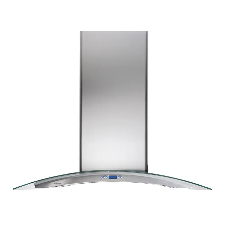
36" island chimney vent hood
Hide thumbs
Also See for ZV925:
- Installation instructions manual (48 pages) ,
- Owner's manual (12 pages) ,
- Installation instructions manual (24 pages)
Table of Contents
Advertisement
Quick Links
Download this manual
See also:
Owner's Manual
Advertisement
Table of Contents

Related Manuals for Monogram ZV925


Summary of Contents for Monogram ZV925
- Page 1 Installation Instructions 36" Island Chimney Vent Hood ZV925 49-80329-4...
-
Page 2: Installation Instructions
Installation Instructions BEFORE YOU BEGIN WARNING: TO REDUCE THE RISK OF FIRE, Read these instructions completely and ELECTRICAL SHOCK OR INJURY, OBSERVE THE FOLLOWING: carefully. A. Use this unit only in the manner intended by the manufacturer. If you have any questions, contact the •... -
Page 3: Table Of Contents
This hood may be vented to the outdoors, or it can be 9'-1" to 10’-1". installed for recirculating operation. This hood can be installed over any Monogram electric or gas cooktop. It cannot be installed over a Monogram Professional cooktop or range. -
Page 4: Advance Planning
Advance Planning ADVANCE PLANNING POWER SUPPLY Ductwork Planning IMPORTANT - (Please read carefully) WARNING: • These vent hoods are equipped for 8" round ductwork. FOR PERSONAL SAFETY, THIS APPLIANCE MUST BE • Determine the exact location of the vent hood. PROPERLY GROUNDED. -
Page 5: Duct Fittings
Advance Planning Total DUCT FITTINGS Equivalent Quantity Equivalent Duct Piece Dimensions Length* Used Length This Hood Must Use an Round, 1 ft. 8 Round Duct. It Can straight (per foot Transition to a length) 3-1/4 x 12 Duct. 3-1/4" x 12" 1 ft. -
Page 6: Installation Preparation
Installation Preparation Possible Hood Mounting DETERMINE INSTALLATION HEIGHT Ceiling Installation Frame Trim Piece • Decorative duct covers are provided to conceal the Height Height (inches) Height (inches) Needed ductwork running to the ceiling. 7'-11" 30 1/2 • This hood can be installed for recirculating 30 1/2 operation. -
Page 7: Tools And Materials Required
Installation Preparation TOOLS AND MATERIALS REQUIRED 3/8" swivel socket or pivoting (NOT SUPPLIED) hex socket with 6" Hammer extensions Duct tape Electric or battery-operated Wire cutter/stripper drill and 3/16" bits, Phillips and Key hole saw flat blade screwdriver bits. Pencil and tape measure 8"... -
Page 8: Parts Provided
Installation Preparation PARTS PROVIDED Locate the parts packed with the hood. 1 charcoal filter for Stainless steel filter recirculating installation Air deflector for recirculating installation HARDWARE PACKAGE Locate and check contents. Screws 6 ceiling shown actual size. Telescoping mounting support frame screws 12 sheet metal... -
Page 9: Construct Ceiling Support
Installation Preparation CONSTRUCT CEILING SUPPORT Plan the Location of the Hood and Ductwork • The hood should extend beyond the front and rear • Use a plumb bob to check the location. The edge of the cooking appliance. countertop/cooktop below the hood must be •... - Page 10 Installation Preparation CONSTRUCT CEILING SUPPORT CONTINUED EXAMPLE B 10-1/16" install cross-framing 16" joist symmetrically spacing over duct/cooktop centerline 2x4 cross framing 8" duct 7-1/16" Front Cooktop Align duct hood outline to center of cooktop Top view – ceiling joists run perpendicular to front of hood EXAMPLE C 10-1/16"...
-
Page 11: Construct Ceiling Support
Installation Preparation CONSTRUCT CEILING SUPPORT CONTINUED 2 x 4 min. 2x 4 Min. • Secure each 2 x 4 block with at least four (4), #10 cross framing Cross Framing wood screws, 3" long (not supplied). Use 8 wood screws total for the two supports. •... -
Page 12: Step 1 Mount Template
Installation Instructions STEP 1 MOUNT TEMPLATE • Align the template with the marks on the ceiling Drill 3/16≤ Pilot Holes Cut a 1≤ Dia. Approx. 1-1/2≤ Wire Access Hole Deep and tape in place. 10-1/16≤ to Centerline of Holes Drill 3/16≤ 7-1/16≤... -
Page 13: Step 3 Cut Duct To Length For Vented Installation
Installation Instructions STEP 3 CUT DUCT TO LENGTH FOR STEP 5 INSTALL HOOD ATTACHMENT VENTED INSTALLATION SCREWS • Measure from House duct house duct to exhaust opening. • Cut the 8" duct length to size. Duct Install 4 • Slip duct over the Duct length attachment... -
Page 14: Step 6 Mount The Hood Onto The Support
Installation Instructions STEP 7 CONNECT CABLES STEP 6 MOUNT THE HOOD ONTO THE SUPPORT WARNING: Two people are required to lift and position the hood onto the support. AVERTISSEMENT : Il faut deux Retainer personnes pour lever et mettre en place a hotte sur clip le support de montage. -
Page 15: Step 8 Connect Electrical
Installation Instructions STEP 8 CONNECT ELECTRICAL • Remove junction box cover and knockout on the Verify that power is turned off at the source. left side. WARNING: If house wiring is not 2-wire Knockout with a ground wire, a ground must be provided by the installer. -
Page 16: Step 9 Prepare The Duct Covers
Installation Instructions STEP 9 PREPARE THE DUCT COVERS STEP 10 INSTALL UPPER DUCT COVER • Remove the plastic protective covering on all • Place the tall duct covers onto the top of the duct pieces. hood. This section has venting holes on one end. •... -
Page 17: Step 11 Install Lower Duct Cover
Installation Instructions STEP 11 INSTALL LOWER DUCT COVER STEP 12 INSTALL DUCT COVER TRIM Front bottom duct cover section Upper (snap into place and secure trim Upper Side with 6 screws – 3 per side) strip trim bracket strip Plan diagram top view Lower trim... -
Page 18: Step 1 Mount Template
Installation Instructions STEP 1 MOUNT TEMPLATE • Align the template with the marks on the ceiling Drill 3/16≤ Pilot Holes Cut a 1≤ Dia. Approx. 1-1/2≤ Wire Access Hole Deep and tape in place. 10-1/16≤ to Centerline of Holes Drill 3/16≤ 7-1/16≤... -
Page 19: Step 3 Install Air Deflector, Cut Duct For Recirculating Operation
Installation Instructions STEP 3 INSTALL AIR DEFLECTOR, STEP 4 INSTALL UPPER SUPPORT FRAME CUT DUCT FOR RECIRCULATING • Raise the upper support OPERATION toward the ceiling. • Thread the house wiring • Temporarily, slide the through one of the large air deflector into the holes, preferably on the support frame. -
Page 20: Step 5 Install Lower Structure To Upper Structure
Installation Instructions STEP 5 INSTALL LOWER STRUCTURE STEP 6 INSTALL BLOWER/MOTOR TO UPPER STRUCTURE • Raise the blower/ motor piece toward the • Slide lower frame into assembled frame. the upper frame. Match the marked alignment • Carefully raise the motor holes. -
Page 21: Step 7, Install Hood Attachment Screws
Installation Instructions STEP 9 CONNECT CABLES STEP 7 INSTALL HOOD ATTACHMENT SCREWS Install 4 Retainer attachment screws clip lights • Install 4 hood attachment screws in the bottom To control panel of the support as shown. Leave 1/4" gap between screw head and support flange. -
Page 22: Step 10 Connect Electrical
Installation Instructions STEP 10 CONNECT ELECTRICAL • Remove junction box cover and knockout on the Verify that power is turned off at the source. left side. WARNING: If house wiring is not 2-wire Knockout with a ground wire, a ground must be provided by the installer. -
Page 23: Step 11 Prepare The Duct Covers
Installation Instructions STEP 11 PREPARE THE DUCT COVERS STEP 12 INSTALL UPPER DUCT COVER • Remove the plastic protective covering on all duct • Place the tall duct covers onto the top of the pieces. hood. This section has venting holes on one end. •... -
Page 24: Step 13 Install Lower Duct Cover
Installation Instructions STEP 13 INSTALL LOWER DUCT COVER STEP 14 INSTALL DUCT COVER TRIM Front bottom duct cover section Upper (snap into place and secure with trim Upper Side 6 screws – 3 per side) strip trim bracket strip Plan diagram top Lower view... -
Page 25: Step 15 Install Filters
Installation Instructions STEP 15 INSTALL FILTERS STEP 16 FINALIZE INSTALLATION IMPORTANT: Check to be sure that the main ON/ • Remove all tape and packing material. OFF switch next to the motor is in the ON position. • Refer to the Owner’s Manual for operating instructions. Charcoal filter •... - Page 26 Notes...
- Page 27 Notes...
- Page 28 Note: While performing installations described in this book, safety glasses or goggles should be worn. For Monogram local service in your area, call ® 1.800.444.1845. Note: Product improvement is a continuing endeavor at General Electric. Therefore, materials, appearance and specifications are subject to change without notice.
Need help?
Do you have a question about the ZV925 and is the answer not in the manual?
Questions and answers