Table of Contents
Advertisement
Quick Links
Download this manual
See also:
User Manual
Advertisement
Table of Contents

Related Manuals for Micronics W6-LI Pentium Pro PCI/ISA


Summary of Contents for Micronics W6-LI Pentium Pro PCI/ISA
- Page 1 W6-LI Pentium Pro PCI/ISA System Board Manual Document Number: 06-00288-02, Rev. 1B October 1996 221 Warren Ave., Fremont, CA 94539-7085...
- Page 2 Micronics assumes no responsibility for any inaccuracies that may be contained in this document. Micronics makes no commit- ments to update or to keep the information in this manual at a current level when changes are made to the product.
-
Page 3: Table Of Contents
Table of Contents Introduction Features Software Compatibility Before You Begin Chapter 1 - Quick Installation Installing the W6-LI Chapter 2 - Configuring the W6-LI Static Electricity Office Environment W6-LI System Board W6-LI Back Panel Connections Jumper Settings Chapter 3 - Installing the W6-LI Introduction System Memory Support Installing the W6-LI... - Page 4 Installing a ISA Peripheral Card Installing a CD-ROM Drive The W6-LI Sound Option Connecting Sound Devices Connecting the Telephony Option Connecting the SCSI Option Chapter 4 - The BIOS Setup Utility Configuration Initial Bootup Setup Running the Setup Procedure Setting the Main Screen Setting the Advanced Screen Security Screen Boot Screen...
-
Page 5: W6-Li System Board Manual
Appendix B - Post Messages Appendix C - Beep and POST Codes Appendix D - Hard Disk Drive Types Appendix E - Updating the System BIOS Appendix F - Warranties and Notices Limited Warranty FCC Statement Declaration of Conformity Glossary Index W6-LI System Board Manual... - Page 6 List of Figures Figure 1.1: Power-Up Screen Figure 2.1: W6-LI System Board Figure 2.2: W6-LI Back Panel Connections Figure 3.1: Installing a 168-Pin DIMM Figure 3.2: Installing a PCI Card Figure 3.3: Installing an ISA Peripheral Card Figure 3.4: Connecting External Sound Devices Figure 4.1: Power-Up Screen Figure 4.2: CMOS Main Screen Figure 4.3: IDE Device Submenu...
-
Page 7: Introduction
Micronics builds all products to exacting standards, using the highest quality components available. We are proud to provide this system board and believe you will be pleased with your purchase. -
Page 8: Features
Introduction Features The W6-LI includes the following features: Dual ZIF socket 8's for Intel Pentium Pro Processor Supports 150, 166, 180 and 200MHz processors One integrated VRM and one VRM header to supply CPU-specific voltages Intel 440FX PCIset Intel PIIX 3 SMC FDC37C93X Ultra I/O chip Support for 60, 66MHz CPU Bus with configuration options to support CPU operation from 150 to 200 MHz... -
Page 9: Software Compatibility
Introduction Two Universal Serial Bus (USB) ports for desktop peripheral expansion (optional) PS/2 style keyboard and mouse connectors Bi-directional parallel port (ECP and EPP compatible) Field upgradeable Flash Phoenix BIOS Software Compatibility The W6-LI system board has been thoroughly tested for compatibility with a variety of operating systems and envi- ronments, including: Windows 95 and Windows NT... -
Page 10: Before You Begin
Introduction Before You Begin This manual will familiarize you with the features, installa- tion and use of your W6-LI. There are several symbols and conventions used throughout this manual to help draw your attention to a feature or to focus on important information: When you see the Magnifying Glass, it refers to something you should take a closer look at before proceeding further. -
Page 11: Chapter 1 - Quick Installation
Chapter 1: Quick Installation Chapter Quick Installation We know that many experienced people prefer to read as little of the documentation as possible. If this sounds like you, here’s the short form to get up and running quickly. Installing the W6-LI 1. -
Page 12: Figure 1.1: Power-Up Screen
Chapter 1: Quick Installation Figure 1-1: Power-Up Screen 9. Set the time and date. Adjust the BIOS settings to match your configuration. If installing an IDE drive, select the IDE device you wish to configure. Press ENTER with Autotype Fixed Disk selected and the BIOS will automatically configure the drive for you (refer to Chapter 4). -
Page 13: Chapter 2: Configuring The W6-Li
Chapter 2: Configuring the W6-LI Configuring the W6-LI Chapter Although the W6-LI system board is packaged in protec- tive materials, it is important to use care while unpack- ing and setting up. Static Electricity The W6-LI is shipped from the factory in an antistatic bag. -
Page 14: W6-Li System Board
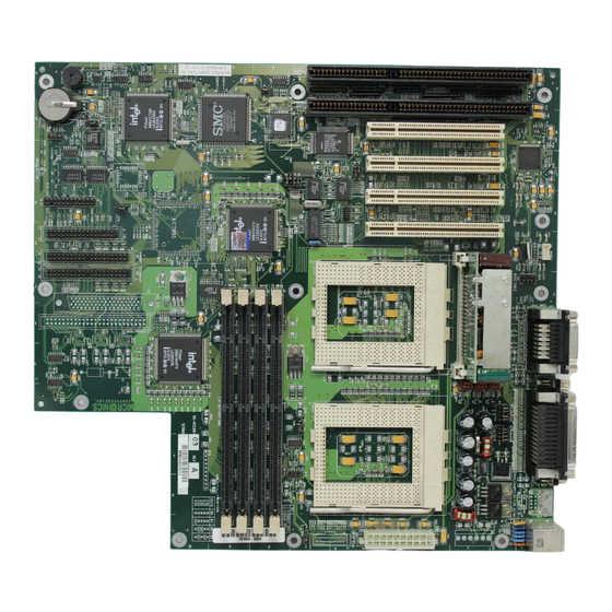
Chapter 2: Configuring the W6-LI W6-LI System Board Figure 2-1: W6-LI System Board W6-LI Back Panel Connections Figure 2-2: W6-LI Back Panel W6-LI System Board Manual... -
Page 15: Jumper Settings
Chapter 2: Configuring the W6-LI Jumper Settings This chapter gives you the jumper settings used for the W6-LI syste board. Table 2-1: Jumper settings to select the CPU frequency. These setting apply to both CPUs. NOTE: Before making your selection, verify that jumper W12 is closed. -
Page 16: Table 2.3: Isa Bus Clock Selection
Chapter 2: Configuring the W6-LI Table 2-3: Jumper settings for the ISA Bus clock frequency selection. Jumper Host Bus Speed ISA Bus Speed Setting 60MHz (default) 7.50MHz Close 66MHz (default) 8.25MHz Close Table 2-3: ISA BUS Clock Settings Table 2-4: Jumper settings to enable or disable the system power supply. Jumper Function Settings... -
Page 17: Table 2.7: Pipelining Mode Settings
Chapter 2: Configuring the W6-LI Table 2-7: Jumper settings for the Host Bus Agents pipelining mode. Host Bus Agents are devices connected to the CPU local bus, which include the CPUs and the 440FX chipset. Host Bus Agents can generate, up to eight at a time, multiple overlapped (or pipelined) bus transactions (or bus cycles). - Page 18 Chapter 2: Configuring the W6-LI Connector Function Notes J19-J20 ISA Bus Expansion Slots Power Supply Connector ATX Standard Front I/O Connector " System Power On/Off 1 - Power; 2 - Ground " Reset Switch 23 - Reset; 22 - Ground "...
-
Page 19: Chapter 3 - Installing The W6-Li
Damage which occurs to the board while adding or removing peripherals or components may void the warranty. If prob- lems arise while installing peripherals, contact the computer dealer where you purchased the peripheral or Micronics’ Technical Support Department. System Memory Support... -
Page 20: Installing The W6-Li
ATX form factor and must be installed in an ATX chassis. NOTE: If you are unfamiliar with installing a system board, Micronics highly recommends that you read the computer user’s manual or contact your dealer’s technical support department. Tools Required... -
Page 21: System Memory
DIMMs. DIMMs Supported The W6-LI supports the following types of 60 or 70ns For long DIMMs: term 8MB (1MBx64/72) reliability, Micronics 16MB (2MBx64/72) recom- 32MB (4MBx64/72) mends using DIMMs with 64MB (8MBx64/72)* gold-plated 128MB (16MBx64/72)* contacts. -
Page 22: Mixing Edo And Fpm Memory
Chapter 3: Installing the W6-LI Upgrade DIMMs one bank at a time. Start with Bank 0, then work your way up (one DIMM per bank), adding memory from the smallest to the largest size. Mixing EDO and FPM Memory The W6-LI can handle a combination of EDO and FPM memory. -
Page 23: Memory Configurations
Chapter 3: Installing the W6-LI Memory Configurations There is no The following tables list the most common memory need to set configurations. The memory available depends on the any jumpers. number of DIMMs installed. When you reboot, the size and type of Memory Bank 0... -
Page 24: Figure 2.1: W6-Li System Board
Chapter 3: Installing the W6-LI Memory Bank 0 Bank 1 Bank 2 Bank 3 64MB 2MBx64/72 2MBx64/72 2MBx64/72 2MBx64/72 64MB 4MBx64/72 2MBx64/72 2MBx64/72 64MB 4MBx64/72 2MBx64/72 1MBx64/72 1MBx64/72 64MB 4MBx64/72 4MBx64/72 64MB 8MBx64/72 80MB 4MBx64/72 2MBx64/72 2MBx64/72 2MBx64/72 80MB 4MBx64/72 4MBx64/72 2MBx64/72 80MB... - Page 25 Chapter 3: Installing the W6-LI Memory Bank 0 Bank 1 Bank 2 Bank 3 128MB 16MBx64/72 128MB 4MBx64/72 4MBx64/72 4MBx64/72 4MBx64/72 128MB 8MBx64/72 4MBx64/72 2MBx64/72 2MBx64/72 128MB 8MBx64/72 4MBx64/72 4MBx64/72 128MB 8MBx64/72 8MBx64/72 160MB 16MBx64/72 2MBx64/72 2MBx64/72 160MB 16MBx64/72 2MBx64/72 1MBx64/72 1MBx64/72 160MB...
- Page 26 Chapter 3: Installing the W6-LI Memory Bank 0 Bank 1 Bank 2 Bank 3 256MB 16MBx64/72 16MBx64/72 256MB 16MBx64/72 8MBx64/72 4MBx64/72 4MBx64/72 256MB 16MBx64/72 8MBx64/72 8MBx64/72 256MB 8MBx64/72 8MBx64/72 8MBx64/72 8MBx64/72 288MB 16MBx64/72 16MBx64/72 2MBx64/72 2MBx64/72 288MB 16MBx64/72 16MBx64/72 4MBx64/72 288MB 16MBx64/72 8MBx64/72...
-
Page 27: Installing The Dimms
Chapter 3: Installing the W6-LI Installing the DIMMs To install the DIMMs, locate the memory banks on the system board and perform the following steps: 1. Hold the DIMM so that the notched edge is aligned with the notch on the DIMM socket (Figure 3-1). 2. -
Page 28: Installing A Cpu
Chapter 3: Installing the W6-LI Installing a CPU The W6-LI is designed to support dual Pentium Pro processors. Follow the steps below to install the main or second processor: 1. Turn off the computer and remove its cover. 2. Locate the ZIF socket illustrated in Figure 2-1. 3. -
Page 29: Installing A Pci Peripheral Card
Chapter 3: Installing the W6-LI Installing a PCI Peripheral Card Micronics PCI slots accommodate all PCI peripherals that meet the PCI 2.1 specifications. Follow the steps below to install a PCI card: 1. Turn the computer system off and remove its cover. -
Page 30: Installing An Isa Peripheral Card
Chapter 3: Installing the W6-LI Installing an ISA Peripheral Card Micronics ISA slots accommodate all standard ISA peripherals. Follow the steps below to install a PCI card: 1. Turn the computer system off and remove its cover. 2. Choose an unused ISA slot and remove the slot cover. -
Page 31: Installing A Cd-Rom Drive
Chapter 3: Installing the W6-LI Installing a CD-ROM Drive If you are installing a CD-ROM drive, Micronics recom- mends the installation of an IDE CD-ROM drive. instructions below will help you with the installation, but also refer to the documentation that accompanied your CD-ROM drive. -
Page 32: The W6-Li Sound Option
Chapter 3: Installing the W6-LI The W6-LI Sound Option You can connect external sound devices to your W6-LI system board to take advantage of the optional sound support (refer to Figure 2.2). The sound option includes 16-bit stereo sound, a game and MIDI port and a telephony header. -
Page 33: Connecting The Telephony Option
Chapter 3: Installing the W6-LI Game Port You can use the Game Port connector to connect an IBM PC compatible joystick or MIDI instrument. Line Out The Line Out jack allows you to connect the audio output of the audio controller to your home stereo, VCR, or amplified speakers. -
Page 34: Connecting The Scsi Option
Chapter 3: Installing the W6-LI Connecting the SCSI Option The W6-LI can be upgraded to include integrated Ultra Wide SCSI PCI throughput (up to 40MBytes/sec data rate). Connectors are provided for Normal (Fast) SCSI (50-pin connector) and Wide (Ultra Wide) SCSI (68-pin connector). -
Page 35: Chapter 4 - The Bios Setup Utility
Chapter 4: The BIOS Setup Utility The BIOS Setup Utility Chapter Configuration After the W6-LI system board and all hardware is in- stalled, the system is ready for configuration. Before turning on the computer, make sure all cables are cor- rectly connected and all jumpers are correctly set. -
Page 36: Figure 4.1: Power-Up Screen
Chapter 4: The BIOS Setup Utility After the system is turned on and goes through a memory test, the Power-Up screen (Figure 4-1) will appear on your monitor: Figure 4-1: Power-Up Screen When “Press <F2> to enter SETUP” appears at the bottom of the screen, press the <F2>... -
Page 37: Running The Setup Procedure
Chapter 4: The BIOS Setup Utility Running the Setup Procedure The W6-LI system board has five primary CMOS con- figuration screens: Main Screen, Advanced Screen, Security Screen, Boot Screen and Exit Screen. To toggle →> and the between the screens, press the right arrow < left arrow <... - Page 38 Chapter 4: The BIOS Setup Utility System Time and Date To set the time, use the <-> key to decrease the number and the <+> key to increase the number. To move the prompt forward, use the <Tab> key; to move the prompt backward, use the <Shift-Tab>...
- Page 39 Chapter 4: The BIOS Setup Utility Choosing Shadowed & Cached (default) caches the shadowed video BIOS for even higher performance. To disable the Video BIOS category, select Disabled. System BIOS The System BIOS category allows you to Shadow or Shadow & Cache the system BIOS. Choosing Shadowed copies the system BIOS into RAM for faster execution.
-
Page 40: Figure 4.3: Ide Device Submenu
Chapter 4: The BIOS Setup Utility Figure 4-3: IDE Device Submenu Autotype Fixed Disk The easiest way to set your IDE devices is to let the BIOS do it for you. When the IDE Device submenu first appears, the Autotype Fixed Disk selection is high- lighted. - Page 41 Chapter 4: The BIOS Setup Utility you are using a SCSI hard drive, select None and refer to the documentation which came with the SCSI adapter. Multiple-Sector Transfers This category determines the number of sectors per block for multiple sector transfers. The options are Disabled (default), 2 Sectors, 4 Sectors, 8 Sectors, and 16 Sectors.
-
Page 42: Setting The Advanced Screen
Chapter 4: The BIOS Setup Utility Setting the Advanced Screen To move to the Advanced screen, use the left and right arrow keys <←/→> keys until you see the screen below. Figure 4-4: Advanced Screen Serial Port A Serial Port A may be set for Auto (default), COM1, COM2, COM3, COM4 or Disabled. - Page 43 Chapter 4: The BIOS Setup Utility Parallel Port The parallel port may be set for Auto (default), LPT1, LPT2, LPT3 or may be disabled. Parallel Port Mode The parallel port may be set for output mode (AT) (default), bidirectional mode (PS/2) and Extended Capa- bilities Port (ECP).
- Page 44 Chapter 4: The BIOS Setup Utility Integrated Sound This selection enables or disables the onboard sound controller. The default setting is Enabled. IRQ12 This selection routes IRQ12 to the PS/2 Mouse (default) or the ISA bus. Plug & Play O/S This selection, when set to Yes, allows the system to work with a Plug and Play operating system such as Windows 95.
-
Page 45: Security Screen
Chapter 4: The BIOS Setup Utility Security Screen The Security screen controls access to the computer. The security screen allows for settings of two passwords. The Supervisor Password allows access to the system and Setup. The User Password allows access to the system, but not to all Setup features. -
Page 46: Figure 4.6: Supervisor Password Submenu
Chapter 4: The BIOS Setup Utility Set Supervisor Password Press the ENTER key to enter the Supervisor Pass- word submenu. Figure 4-6: Supervisor Password Submenu Type the password and press the ENTER key. Retype the password and press the ENTER key again. Write down the password somewhere safe so it will not be forgotten. - Page 47 Chapter 4: The BIOS Setup Utility Password on Boot When enabled, the system requires a password upon power up. Either the Supervisor or User Password may be entered. Diskette Access This selection allows floppy disk access with an option of the supervisor or user.
-
Page 48: Boot Screen
Chapter 4: The BIOS Setup Utility Boot Screen The Boot screen allows you to configure the power up system configuration settings. Figure 4-7: Boot Screen Boot Sequence This selection will read the diskette drive (default) and the hard drive in sequence on boot. Setup Prompt If this selection is enabled, the message "Press F2 to enter Setup"... -
Page 49: Exit Screen
Chapter 4: The BIOS Setup Utility prompt. If this selection is disabled, the system will always attempt to boot. Numlock Setting this to ON activates Numlock upon boot. Setting this to Auto activates Numlock if the BIOS detects a numeric keyboard. It may also be set to OFF (default). Exit Screen After you complete configuring the BIOS, select the Exit screen. - Page 50 Chapter 4: The BIOS Setup Utility W6-LI System Board Manual...
-
Page 51: Chapter 5 - Installing Device Drivers
Chapter 5: Installing Device Drivers Chapter Installing Device Drivers This chapter explains how to install the software device drivers and utilities necessary to utilize the optional sound and SCSI support. Other drivers and utilities are available through our online services. About Device Drivers Device drivers are necessary for the computer system to communicate with devices such as CD-ROM drives,... -
Page 52: Installing The Scsi Drivers
Chapter 5: Installing Device Drivers 4. Insert the sound driver disk into your floppy drive. 5. If you are using Windows 3.1x, go to the Program Man- ager File menu, click on Run and type A:\SETUP . 6. If you are using Windows 95, refer to the Windows 95 user’s manual for instructions on how to install sound drivers. -
Page 53: Appendix A: Technical Information
Appendix A: Technical Information Specifications Appendix Part Number: 09-00288-01 Processor: Dual ZIF socket 8's for Intel Pentium Pro Processor. Supports 150, 166, 180 and 200MHz processors. One integrated VRM and one VRM header to supply CPU-specific voltages. Chipset: Intel 440FX PCIset with PIIX 3. SMC FDC37C93X Ultra I/O chip. -
Page 54: Environmental Specifications
Two resident 40-pin IDE connector. Multiple sector transfer support. Auto detection of add-in IDE board. Environmental Specifications The environment in which the W6-LI is located is critical. Micronics recommends the following environmental specifications: Temperature Range Operating: 50 to 104 degrees Fahrenheit (10 to 40 degrees Celsius). -
Page 55: Battery Disposal
Appendix A: Technical Information Battery Disposal WARNING: Please do not open battery, dispose of in fire, recharge, put in backward or mix with used or other battery types. The battery may explode or lea and cause personal injury. W6-LI System Board Manual... -
Page 56: Support And Information Services
Engineers will be glad to help you. You can contact us via telephone, fax or BBS. Before calling Technical Support please have the following information ready: The model name and 09 part number of your Micronics product. Your computer information such as CPU type, operating system, amount of installed memory and other peripherals installed in your computer. -
Page 57: Table A.1: Support And Information Services
World Wide Web - Product 24 hours a day http://www.micronics.com information, technical support, press 7 days a week releases and other helpful information Customer Service - Order Micronics M-F: 8:00am to (800) 577-0977 and Orchid products 5:00pm (PST) (510) 651-3666 (Fax) France... - Page 58 Appendix A: Technical Information W6-LI System Board Manual...
-
Page 59: Appendix B - Post Messages
Appendix B: POST Messages Appendix POST Messages The following table lists the Power On Self Test (POST) messages, possible causes and solutions. Message Possible Cause Solution DISKETTE DRIVE A Drive A failed or is Check Setup and cable FAILURE missing. connections. - Page 60 Appendix B: POST Messages Message Possible Cause Solution MONITOR TYPE Monitor type not Run Setup and enter DOES NOT MATCH correctly identified in correct monitor type. CMOS Setup. OPERATING Operating system Check Setup to see if SYSTEM NOT cannot be located on Drive A: and C: are FOUND Drive C: or Drive A:...
-
Page 61: Appendix C - Beep And Post Codes
Appendix C: Beep and POST Codes Beep and POST Codes Appendix Beep codes are a series of beeps sent through the speaker which indicate a problem during the Power On Self Test (POST). If text appears on the video screen, the W6-LI has completed POST;... - Page 62 Appendix C: Beep and POST Codes Code Beeps POST Routine Description Verify Real Mode. Get CPU type. Initialize system hardware. Initialize chipset registers with initial POST values. Get in POST Reg. Initialize CPU registers. Initialize cache initial POST values. Initialize I/O. Initialize the localbus IDE.
- Page 63 Appendix C: Beep and POST Codes Code Beeps POST Routine Description Initialize all video adapters in system. Shadow video BIOS ROM. Display copyright notice. Display CPU type and speed. Initialize EISA board. Test keyboard. Set key click if enabled. Enable keyboard. 2-2-3-1 Test for unexpected interrupts.
- Page 64 Appendix C: Beep and POST Codes Code Beeps POST Routine Description Set up Power Management. Enable hardware interrupts. Set time of day. Check key lock. Initialize typematic rate. Erase F2 prompt. Scan for F2 keystroke. Enter SETUP. Clear in-POST flag. Check for errors.
-
Page 65: Appendix D: Hard Disk Drive Types
Appendix D: Hard Disk Drive Types Appendix Hard Disk Drive Types The following table lists the IDE hard disk types sup- ported by the W6-LI. Type Cylinders Heads Write Sectors Size Precomp none none none none none none none none 1024 none none... - Page 66 Appendix D: Hard Disk Drive Types Type Cylinders Heads Write Sectors Size Precomp none none 1024 none 1024 none 1024 none none W6-LI System Board Manual...
-
Page 67: Appendix E - Updating The System Bios
Appendix E: Updating the System BIOS Updating the System BIOS Appendix The Micronics system boards are designed so that the BIOS can be reprogrammed using a BIOS file. You can easily FLASH a BIOS by following the steps below: 1) After downloading the appropriate BIOS file from our BBS or Website, extract it to a bootable MS- DOS 6.X diskette. - Page 68 Appendix E: Updating the System BIOS $50.00. Overnight shipping costs an additional $10.00. (Price and availability subject to change.) If you prefer to send your system board in for the upgrade, the RMA department offers this service free of charge if your system board is under warranty.
-
Page 69: Appendix F: Warranties And Notices
Micronics or its authorized service centers will, at Micronics’ option, repair or re- place the product at no additional charge. The warranty does not cover loss or damage which occurs... - Page 70 Micronics will not be liable for any lost profits or any indirect, special incidental or consequential damages in connection with the product, even if Micronics has been advised of the possibility of such damages.
-
Page 71: Fcc Statement
Consult your dealer or an experienced radio/TV technician for help. To meet FCC requirements, shielded cables are required. NOTE: Changes or modifications not expressly approved by Micronics could void your authority to operate the equipment. W6-LI System Board Manual... -
Page 72: Declaration Of Conformity
Appendix F: Warranties and Notices Declaration of Conformity Application of Council Directives 89/336/EEC. Standards to which the conformity is declared: EN55022 EN50082-1 Manufacturer's Name: Micronics Computers, Inc. Manufacturers Address: 221 Warren Avenue Fremont, California 94539 Telephone: (510) 651-2300 Fax: (510) 651-9450 Type of Equipment:... -
Page 73: Glossary
Glossary Glossary Byte - A group of adjacent bits treated 16550 UART - A high speed chip for as a unit. Eight bits are typically con- controlling serial ports. Although un- necessary for a mouse, it is required sidered one byte. Also called a char- for modems that are 14,400 baud or acter. - Page 74 Glossary read/write head across the disk’s sur- type of ROM chip that can be pro- face in order to read or write data in grammed with relatively simple tools magnetic code. that will retain its data until erased. It can only be erased by exposing the cir- DRAM - An acronym for Dynamic cuitry in the chip to ultraviolet light.
- Page 75 Glossary the bytes arrive simultaneously, as op- ROM - An acronym for Read Only posed to serial transmission in which Memory. A type of memory that re- bits arrive one by one. tains its data without requiring power. Once written, it cannot be modified. Parallel Port - A connection for a See EPROM and Flash ROM.
- Page 76 Glossary Wide SCSI - A SCSI-2 enhancement Although they are faster than DRAM, that allows data to be transferred 16 they hold less data and are more ex- or 32 bits at a time on the SCSI bus pensive. instead of 8 bits at a time. Synchronous - Protocols that require the clocks of communicating ma- Write-Back Cache - Upon a cache...
-
Page 77: Index
Index Index Chassis - 18 Form Factor - 5 Power Supply - 18 Back Panel Connections - 12 Battery Disposal - 53 Beep and POST Codes - 59 BIOS Configuration - 33 Setup - 33 Bulletin Board System (BBS) - 55 Configuring the W6-LI - 11 Connecting SCSI Option - 32... - Page 78 Index Environmental Specifications - 52 Error Checking (ECC) - 17 Fast Page Mode (FPM) Memory - 17, 19 Hard Disk Drive Types - 63 Help Bulletin Board System (BBS) - 55 Telephone Numbers - 55 Troubleshooting - 57, Installation CD-ROM Drive - 29 CPU - 26 Installing your W6-LI - 17...
- Page 79 Index W6-LI Back Panel Connections - 12 W6-LI System Board Diagram - 12 Memory Configurations - 21 Installing - 25 Mixing - 20 Removing - 25 Supported - 17, 19 Online Services - 55 POST Messages - 57 SCSI Option - 32 Sound Option - 30 Specifications - 51 System BIOS - 65...
- Page 80 Index Updating the System BIOS - 65 Utility Programs Advanced Screen - 40 BIOS Setup - 33 Boot Screen - 46 Exit Screen - 47 IDE Device Submenu - 44 Main Screen - 35 Security Screen - 43 World Wide Web - 55 W6-LI System Board Manual...
Need help?
Do you have a question about the W6-LI Pentium Pro PCI/ISA and is the answer not in the manual?
Questions and answers