
Subscribe to Our Youtube Channel
Related Manuals for Micronics M54Pe


Summary of Contents for Micronics M54Pe
- Page 1 M54Pe PCI/EISA Dual Pentium Processor System Board Manual Document Number: 06-00210-05, Rev. 1B November 1995 221 Warren Ave., Fremont, CA 94539-7085...
- Page 2 Copyright Notices Micronics Computers, Inc. The information contained in the M54Pe PCI/EISA Dual Pentium Processor system board manual has been carefully checked and is believed to be accurate. Micronics assumes no responsibility for any inaccuracies that may be contained in this document. Micronics makes no commitments to update or to keep the information in this manual at a current level when changes are made to the product.
- Page 3 1. Make backup copies of your installation and configuration diskettes. 2. Ground yourself to prevent damaging static discharge, then remove the M54Pe from its packaging. 3. Configure and verify the system board’s jumper settings. (See Jumper Settings in Chapter 2) 4.
- Page 4 8. Set the time and date. Adjust the BIOS settings to match your configuration. If installing an IDE drive, select the IDE device you wish to configure. Press <Enter> with Autotype Fixed Disk selected and the BIOS will automatically configure the drive for you. (See Chapter 4) 9.
-
Page 5: Table Of Contents
Software Compatibility ............. Configuring the M54Pe ............Static Electricity ................ Office Environment ..............M54Pe Components..............Jumper Settings ................. Installing the M54Pe, System Memory, CPUs and Peripherals ................. Installation of the M54Pe ............Tools Required ..................Equipment Required ................System Memory ................ - Page 6 Diskette A or B ..................IDE Devices (Hard Disk Setup) ............. Video System ..................Video BIOS Shadow ................System Memory ..................Extended Memory .................. Cache State ..................... Setting the Advanced Screen ............ Boot Options ..................Integrated Peripherals ................Plug and Play O/S .................. Security Screen ..................
- Page 7 Hard Disk Drive Types ............Specifications ..............Environmental Specifications ............D-2 Temperature Range ................Relative Humidity .................. Battery Disposal ................D-3 FCC Warning Statement ............Glossary ..................Limited Warranty ..............Non-Warranty Service..............
- Page 8 List of Figures Figure 2-1: M54Pe System Board ..............Figure 3-1: Installing a 72-Pin SIMM ............Figure 3-2: Upgrading the External Cache ..........Figure 3-3: Installing a PCI Card ..............Figure 3-4: Installing an EISA Card ............Figure 3-5: Installing a Plug & Play Card ..........
-
Page 9: Introduction
The M54Pe is a dual Pentium processor board and is the most powerful Intel-based product on the market. You can operate the M54Pe with a single Pentium processor or add a second matching processor for increased performance. -
Page 10: Features
Bi-directional parallel port that is EPP and ECP compatible (see Specifications). Upgradeable Flash Phoenix BIOS. Software Compatibility The M54Pe system board has been thoroughly tested for compatibility with a variety of operating systems and environments, including: Windows and Windows NT OS/2 version 2.11 & SMP... -
Page 11: Configuring The M54Pe
After you have grounded yourself, ground the M54Pe via the solder pads surrounding one of its mounting holes. Once the M54Pe is removed from its packaging, place it on top of the antistatic bag. Carefully inspect the board for damage which may have occurred during shipment. -
Page 12: M54Pe Components
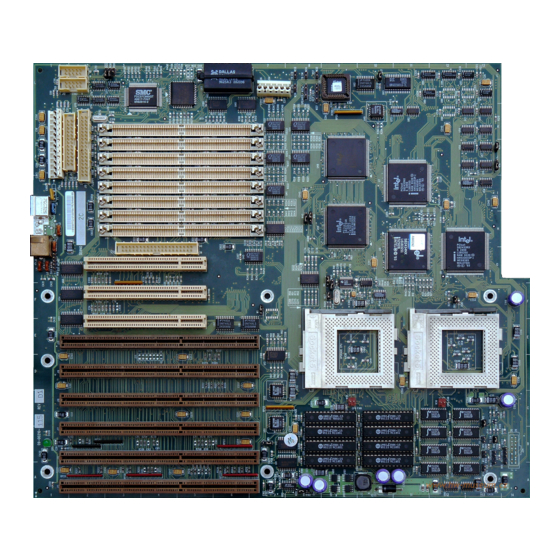
Micronics M54Pe System Board Manual M54Pe Components Figure 2-1 M54Pe System Board... -
Page 13: Jumper Settings
Jumper Settings Jumper Settings Table 2-1 lists the jumper settings to select between write-back and write- through cache. Jumper Function Setting write-through close write-back (default) open Table 2-1 Cache Type Selection Table 2-2 lists the jumper settings to select the speed of the CPU. CPU Speed 75MHz 90MHz... -
Page 14: Table 2-5 Secondary Ide Controller Irq Selection
Micronics M54Pe System Board Manual Table 2-5 lists the jumper settings to set the secondary IDE controller for IRQ14, IRQ15, or Disabled. If you set this for IRQ14, you must disable the PCI IDE controller (Table 2-4). Jumper Function Setting... -
Page 15: Table 2-8 Peripheral And Case Connections
Jumper Settings Table 2-8 lists the jumper settings for case and peripheral connections. Jumper Function Notes PCI IDE Connector Primary ISA IDE Connector Secondary Floppy Connector Parallel Port Connector Can be disabled at the CMOS configuration screen. Serial Port (Com1) Can be disabled at the CMOS configuration screen. -
Page 16: Installing The M54Pe, System Memory, Cpus And Peripherals
Installing the M54Pe, System Memory, CPUs and Peripherals This section explains how to install the M54Pe system board, SIMMs, CPUs, and peripherals. Warning: Before installing or removing any peripherals or components, make sure you have a clear work space and that you adhere to all anti- static precautions described on page 2-1. -
Page 17: Installation Of The M54Pe
Installation of the M54Pe The installation of the M54Pe system board depends on the type of case you use. The M54Pe is a Standard AT motherboard and is likely to be limited to tower cases. If you are unfamiliar with installing a system board, Micronics highly recommends you read the computer user’s manual or contact your dealer’s... -
Page 18: System Memory
System Memory System memory devices, commonly known as SIMMs (Single Inline Memory Modules), are necessary to operate the M54Pe system board. The M54Pe has eight SIMM sockets and can be upgraded to 512 Megabytes of RAM. This section will explain the type of SIMMs supported, list the rules of adding memory to the M54Pe, give some examples of common memory configura- tions, and show how to physically install the new SIMMs. -
Page 19: Common Memory Configurations
Micronics M54Pe System Board Manual Common Memory Configurations The following table (Figure 3-1) lists the most common memory configura- tions. The M54Pe will accept any combination of SIMMs as long as the rules in the previous section are followed. Memory... -
Page 20: Installing The Simms
Installing System Memory and Add-On Peripherals Installing the SIMMs To install the SIMMs, locate the memory banks on the system board and perform the following steps: Hold the SIMM so that the notched edge is aligned with the notch on the SIMM socket (Figure 3-1). -
Page 21: Installing A Cpu
Micronics M54Pe System Board Manual Installing a CPU The M54Pe is designed to support dual Pentium processors. Follow the steps below to install either the host or the upgrade processor: Turn off the computer and remove its cover. Locate the ZIF socket illustrated in Figure 2-1. -
Page 22: Installing Cache Memory
Installing Cache Memory In addition to the 16K of internal (L1) cache built into the Pentium proces- sors, the M54Pe also supports external (L2) cache. The M54Pe is available with 256K or 512K external cache. To upgrade to 512K cache, install eight 32Kx8-15ns SRAMs into the open SRAM sockets (Figure 3-2). -
Page 23: Installing A Pci Peripheral Card
Micronics M54Pe System Board Manual Installing a PCI Peripheral Card Micronics PCI slots accommodate all PCI peripherals which meet the PCI 2.0 specifications. Complete the following steps to install a PCI card: Turn the computer system off and remove its cover. -
Page 24: Installing An Eisa Peripheral Card
Installing System Memory and Add-On Peripherals Installing an EISA Peripheral Card Micronics EISA slots accommodate all EISA peripherals which meet the EISA standard. Complete the following steps to install an EISA card: Turn the computer system off and remove its cover. -
Page 25: Installing A Plug & Play Peripheral Card
Micronics M54Pe System Board Manual Installing a Plug & Play Peripheral Card Micronics EISA slots accommodate all ISA Plug & Play peripherals which meet the Plug and Play standard. Complete the following steps to install a Plug and Play card: Turn the computer system off and remove its cover. -
Page 26: The Bios Setup Utility
The BIOS Setup Utility Configuration After the M54Pe system board and all hardware is installed, the system is ready for configuration. Before turning on the computer, make sure all cables are correctly connected and all jumpers are correctly set. It is recommended you keep the computer cover off the first time you boot the system. -
Page 27: Setup
Micronics M54Pe System Board Manual Setup The Setup program is used to configure the computer’s BIOS (Basic Input/ Output System). The computer’s BIOS is responsible for configuring the motherboard and providing hardware information to the operating system. In order for the computer to run properly, run the Setup procedure after first installing the system board and whenever you make a hardware change to the system. -
Page 28: Running The Setup Procedure
The BIOS Setup Utility Running the Setup Procedure The M54Pe system board has four primary CMOS configuration screens: the Main Screen (Figure 4-2), the Advanced Screen (Figure 4-4), the Security Screen (Figure 4-7), and the Exit Screen (Figure 4-9). To toggle between the screens, press the right arrow <→>... -
Page 29: Diskette A Or B
Micronics M54Pe System Board Manual up and down arrows<↑/↓> to highlight the System Date and follow the same procedure used to set the time. Diskette A or B To configure a floppy drive added to or removed from your computer, use the up and down arrow keys <↑/↓>... -
Page 30: Video System
The BIOS Setup Utility Do not adjust the rest of the settings unless absolutely necessary. The BIOS will automatically enter the optimal settings. Video System This sets the type of video board installed into the system. You may choose from: VGA/SVGA (default), CGA 80x25, MONO, and Not Installed. Video BIOS Shadow Enabling the category allows you to “Shadow”... -
Page 31: Setting The Advanced Screen
Micronics M54Pe System Board Manual Setting the Advanced Screen The first page of the Advanced Screen (Figure 4-4) has two submenus: Boot Options (Figure 4-5) and Integrated Peripherals (Figure 4-6). Use the up and down arrows <↑/↓> to select a menu and press <Enter>. -
Page 32: Figure 4-5 Boot Options Submenu
The BIOS Setup Utility Figure 4-5 Boot Options Submenu Boot Sequence This category selects the order the system searches for a boot disk and can be set for: A: then C: C: then A: C: only Swap Floppies This category can be set to remap the floppy drives. It can be set for NOR- MAL (default) or SWAPPED. -
Page 33: Integrated Peripherals
Micronics M54Pe System Board Manual Post Errors When enabled, this category allows the system to display the “Press <F1> to resume, <F2> to SETUP” and pause if errors occur during boot. If disabled, the system will ignore any errors and will always attempt to boot. -
Page 34: Plug And Play O/S
The BIOS Setup Utility Memory Gap When enabled, this category removes the memory between 15 and 16 mega- bytes from the system. This one megabyte hole will allow some ISA network cards to map into this memory space. Banyon network cards require this feature. -
Page 35: User Password Is
Micronics M54Pe System Board Manual User Password is If a User Password has been set up for the system, it will read “User Password is ENABLED.” If the password has not been set up, it will be disabled (default). Set Supervisor Password Press the <Enter>... -
Page 36: Password On Boot
The BIOS Setup Utility Password on Boot When enabled, the system will require a password to be entered upon boot. Either the Supervisor or User Password may be entered. Diskette Access This category allows floppy disk access with an option of the supervisor or user. -
Page 37: Exit Screen
Micronics M54Pe System Board Manual Exit Screen After you have completed configuring the BIOS, select the Exit Screen (Figure 4-9). Figure 4-9 Exit Screen Choose “Save Changes and Exit” and reboot the computer. After running the EISA configuration utility explained in Chapter 5, the computer will be ready for use. -
Page 38: Eisa Utility
EISA Utility Introduction The M54Pe is shipped with the Micro Computer System EISA Con- figuration Utility. The EISA Configuration Utility is a software utility designed to configure EISA peripherals. The MCS EISA utility is designed to optimize the performance of your EISA peripherals and to maintain conflict-free configuration informa- tion. -
Page 39: Starting The Utility
Micronics M54Pe System Board Manual Starting the Utility Perform the following steps to start the EISA utility: Insert the System Configuration diskette into Drive A (or B). At the A: prompt, type “cf” and press <Enter>. The Configuration Introduction screen will appear (Figure 5-1). -
Page 40: Main Menu
The EISA Utility Main Menu After pressing <Enter>, the main menu appears. The main menu lists 5 steps for configuring the system board. To select a step, highlight the appropriate selection, and press <Enter>. Figure 5-2 shows the main menu. Figure 5-2 EISA Configuration Main Menu Step 1: Important EISA Configuration Information... -
Page 41: Step 2: Add Or Remove Boards
Micronics M54Pe System Board Manual Step 2: Add or Remove Boards When this section is accessed, the utility scans and locates the EISA boards installed. This section allows you to add or remove any EISA, PCI, and ISA Plug and Play peripherals. -
Page 42: Figure 5-4 Adding An Eisa Configuration (Cfg) File
The EISA Utility Figure 5-4 Adding an EISA Configuration (CFG) File When you are finished installing the EISA CFG files, press the <F10> key. -
Page 43: Step 3: View Or Edit Details
Micronics M54Pe System Board Manual Step 3: View or Edit Details When you select the “View or Edit Details” menu (Figure 5-5), a display of your system resources appears. You may edit this menu to optimize the system performance and allocation of resources. -
Page 44: Figure 5-6 Advanced Submenu
The EISA Utility Figure 5-6 Advanced Submenu Lock/Unlock Boards Locking a board will prevent changes from being made to a board’s settings. You may lock or unlock each board individually. View Additional Systems Information Menu This is another submenu which will allow you to view board specifications, system specifications, used resources, and available resources. -
Page 45: Step 4: Examine Switches Or Print Report
Micronics M54Pe System Board Manual Step 4: Examine Switches or Print Report Examine Switches This section displays a listing of the motherboard jumper settings. Print Report This feature is not currently supported. Step 5: Save and Exit Save the new configuration when you exit the utility. When you select Step 5, the Save and Exit Screen appears. -
Page 46: Post Messages
POST Messages The following table lists the Power On Self Test (POST) messages, possible causes, and solutions. Message Possible Cause Solution DISKETTE DRIVE A Drive A failed or is Check Setup and cable FAILURE missing. connections. DISKETTE DRIVE B Drive B failed or is Check Setup and cable FAILURE missing. - Page 47 Micronics M54Pe System Board Manual Message Possible Cause Solution MONITOR TYPE Monitor type not Run Setup and enter DOES NOT MATCH correctly identified in correct monitor type. CMOS Setup. OPERATING Operating system Check Setup to see if SYSTEM NOT cannot be located on...
-
Page 48: Beep And Post Codes
Beep and POST Codes Beep codes are a series of beeps sent through the speaker which indicate a problem during the Power On Self Test (POST). If text appears on the video screen, the LPM30 has completed POST; any other tone from the speaker indicates something other than a POST error. - Page 49 Micronics M54Pe System Board Manual Code Beeps POST Routine Description Verify Real Mode. Get CPU type. Initialize system hardware. Initialize chipset registers with initial POST values. Get in POST Reg. Initialize CPU registers. Initialize cache initial POST values. Initialize I/O.
- Page 50 Beep and POST Codes Code Beeps POST Routine Description Initialize all video adapters in system. Shadow video BIOS ROM. Display copyright notice. Display CPU type and speed. Initialize EISA board. Test keyboard. Set key click if enabled. Enable keyboard. 2-2-3-1 Test for unexpected interrupts.
- Page 51 Micronics M54Pe System Board Manual Code Beeps POST Routine Description Set up Power Management. Enable hardware interrupts. Set time of day. Check key lock. Initialize typematic rate. Erase F2 prompt. Scan for F2 keystroke. Enter SETUP. Clear in-POST flag. Check for errors.
-
Page 52: Hard Disk Drive Types
Hard Disk Drive Types The following table lists the hard disk types supported by M54Pe. Type Cylinders Heads Write Sectors Size Precomp none none none none none none none none 1024 none none none 1218 none 1224 none... - Page 53 Micronics M54Pe System Board Manual Type Cylinders Heads Write Sectors Size Precomp none none 1024 none 1024 none 1024 none none...
-
Page 54: Specifications
Specifications Host Processor 90MHz or 100MHz Pentium processor. Upgrade Processor 90MHz or 100MHz Pentium processor. Chipset Intel Neptune Chipset. CPU Clock Select Frequency synthesizer chip. Jumper selectable CPU selection. Form Factor Full size (12" x 13.75"). 6 layer PCB. Expansion Five 32-bit EISA slots. -
Page 55: Environmental Specifications
LBA support. Clock Benchmarq Real Time Clock. Environmental Specifications The environment in which the M54Pe is located is critical. Micronics recommends the following environmental specifications: Temperature Range Operating: 50 to 104 degrees Fahrenheit (10 to 50 degrees Celsius). Non -Operating: 50 to 140 degrees Fahrenheit (10 to 60 degrees Celsius). -
Page 56: Battery Disposal
Battery Disposal Warning: DO NOT: open battery; dispose of in fire; recharge; put in backwards, mix with used or other battery types. May explode or leak and cause personal injury. -
Page 57: Fcc Warning Statement
Consult your dealer or an experienced radio/TV technician for help. To meet FCC requirements, shielded cables and power cords are required. Note: Changes or modifications not expressly approved by Micronics could void the user’s authority to operate the equipment. - Page 58 Micronics M54Li System Board Manual Declaration of Conformity Application of Council Directives 89/336/EEC and 72/23/EEC. Standards to which the conformity is declared: EN55022 EN50082-1 EN 60950 Manufacturer's Name: Micronics Computers, Inc. Manufacturers Address: 221 Warren Avenue Fremont, California 94539 Tel: (510) 651-2300...
-
Page 59: Glossary
Glossary Glossary Byte - A group of adjacent bits treated as a unit. 16550 UART - A high speed chip for controlling Eight bits are typically considered one byte. Also serial ports. Although unnecessary for a mouse, it called a character. is required for modems that are 14,400 baud or faster. - Page 60 Micronics M54Pe System Board Manual EISA - An acronym for Extended Industry L1 Cache - See Internal Cache. Standard Architecture. EISA is a bus design standard which is fully backward compatible with L2 Cache - See External Cache. the ISA bus. Although it is a 32-bit bus, it only runs at 8MHz.
- Page 61 Glossary Plug and Play - A standard developed to ensure easy installation of peripherals. Theoretically, a SRAM - An acronym for Static Random Access newly installed card will automatically configure Memory. A type of memory that can retain data itself and work properly without requiring jumper without requiring a regular clock signal.
- Page 62 Micronics M54Pe System Board Manual...
-
Page 63: Limited Warranty
A receipt or copy of the invoice with the date of purchase from a Micronics reseller is required before any warranty service can be rendered. Service can be obtained by calling Micronics for a Return Merchandise Authorization (RMA) Number. -
Page 64: Non-Warranty Service
Micronics M54Pe System Board Manual Micronics will not be liable for any lost profits or any indirect, special incidental or consequential damages in connection with the product, even if Micronics has been advised of the possibility of such damages. Micronics makes no warranties or representations as to performance of products or as to service to distributor or to any person, except as set forth in Micronics;...
Need help?
Do you have a question about the M54Pe and is the answer not in the manual?
Questions and answers