Table of Contents

Related Manuals for DVTEL ioimage mmp100dn


Summary of Contents for DVTEL ioimage mmp100dn
- Page 1 DVTEL INC. 65 Challenger Road Ridgefield Park, NJ 07660 mmp100dn Installation Manual The contents of this guide may not be reproduced or reprinted in whole or in part without the express written permission of DVTEL, INC. Rev E March 2014...
-
Page 3: Table Of Contents
Reset by Removing the Power Supply ..............15 Solo Setup ........................15 Appendix ..........................16 A.1. Technical Specifications ....................17 A.2. Connecting Leads to a Spring Clamp Terminal Block ........... 19 A.3. Solo Setup Window ...................... 20 A.4. Troubleshooting ......................22 Contacting DVTEL .........................25... - Page 4 Figure 4: mmp100dn Side Panel ....................... 5 Figure 5: mmp100dn Front Panel ......................5 Figure 6: mmp100dn Camera Fitted with DC Iris Lens and DC Iris Cable ..........8 Figure 7: DNA Discovery Window ......................10 Figure 8: Connecting a Microphone to the Unit ..................11 Figure 9: Loudspeaker Connection to the Unit ..................
-
Page 5: Revision History
Document Information Revision History Version Date Author Comments Rev D April 2013 Alan Singer Added Solo Setup. Updated look and feel. Rev E March 2014 Alan Singer Added DNA to section 3.2.4. Updated look and feel. -
Page 7: Document Information
This document contains proprietary information belonging to DVTEL, Inc. This information is supplied solely for the purpose of assisting explicitly the licensee of the DVTEL units. No part of this document contents may be used for any other purpose, disclosed to any third party or reproduced by any means, electronic or mechanical, without the express prior written permission of DVTEL, Inc. - Page 8 DVTEL, Inc. and its agents make no guarantees or warranties to the suitability for the users’ intended use. DVTEL, Inc. accepts no responsibility for improper use or incomplete security and safety measures.
- Page 9 Document Information Warning: 1. The camera cover is an essential part of the product. Do not open or remove it. 2. Never operate the camera without the cover in place. Operating the camera without the cover poses a risk of fire and shock hazards 3.
- Page 10 Installation Manual Caution: To avoid damage from overheating or unit failure, assure that there is sufficient temperature regulation to support the unit’s requirements (cooling/heating). Operating temperature should be kept in the range 0° to 50°C (32° to 122°F), with no more than 95% non-condensing humidity.
-
Page 11: Introduction
The mmp100dn camera supports Picture-in-Picture (PiP), in which one video clip or stream is displayed on the full TV screen at the same time as another video clip or stream is overlaid on a smaller window. The camera also supports swapped PiP, so that you can switch displaying the video on the full screen or the smaller window. -
Page 12: Items Included In The Package
The PoE injector is packed separately. Note: 1. ioimage cameras are not supplied with a lens. A variety of lenses for the mmp100dn are available as accessories from DVTEL. Contact info@dvtel.com request the ioimage HTML Edition Product Selection Matrix, which includes a list of available lenses. -
Page 13: Hardware Description
The back panel of the unit includes the following connections: Item Description ETHERNET This port is used to interface with the Ethernet network (10/100 Mbps). When 802.3af PoE using the PoE Injector, the camera receives power through this connector. See Port Figure 3: mmp100dn Back Panel (page 3). - Page 14 AUDIO Audio interface to/from the camera. The stereo 3.5 mm plug requires a splitter IN/OUT cable to separate the audio input and output signals (supplied by DVTEL). (Plug) Enables remote listening to the sounds captured by a microphone connected to the camera through this interface.
-
Page 15: Side Panel
Introduction 2.2.2 Side Panel The following image shows the side panel of the mmp100dn camera. Figure 4: mmp100dn Side Panel The side panel of the unit includes the following item: Item Description DC Iris For connecting the Iris Control Cable from a DC Iris lens to the unit. -
Page 17: Installing And Connecting The Unit
Installing and Connecting the Unit 3 Installing and Connecting the Unit This section describes how to install and connect the unit and includes the following sections: Installing the Unit (page 7) Connecting the Unit (page 7) Resetting the Unit (page 15) Note: After connecting the unit, proceed to configure the unit as described in the HTML Edition... -
Page 18: Fitting A Lens To The Unit
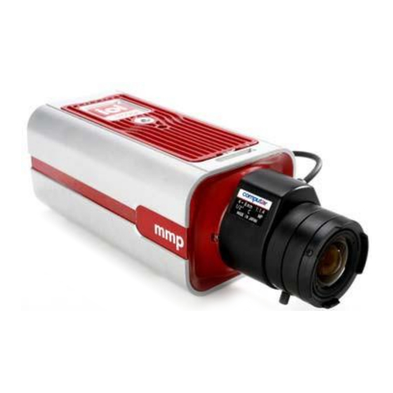
If you are using a DC Iris lens (optional), connect the DC Iris cable to the DC Iris connector on the side of the camera (see Figure 6). Figure 6: mmp100dn Camera Fitted with DC Iris Lens and DC Iris Cable 3.2.2 Grounding the Unit The unit must be grounded according to local regulations and codes. -
Page 19: Connecting The Unit To The Power Supply
12-24/24V on the back panel, using the supplied spring clamp connector. See Figure 3: mmp100dn Back Panel (page 3). For more information on how to use the spring clamp connectors to connect the power leads, see Connecting Leads to a Spring Clamp Terminal Block (page 19). -
Page 20: Connecting The Unit To The Network
Connect a PC/laptop directly to the unit using a network cable connected to the ETHERNET port located on the back panel of the unit. See Figure 3: mmp100dn Back Panel (page 3). Change the IP address according to your specific requirements. See following section. -
Page 21: Connecting A Microphone To The Unit
Connect the audio splitter cable (jack) connector to the AUDIO IN/OUT port located on the back panel of the unit. See Figure 3: mmp100dn Back Panel (page 3). Connect the audio input RCA connector on the other end of the audio splitter cable to the... -
Page 22: Connecting A Loudspeaker To The Unit
To connect the unit analog video output to an analog device Connect the VIDEO OUT of the mmp100dn to the analog device video input (for example, the VIDEO IN of a monitor) using a 75Ω video coax cable with BNC connectors. -
Page 23: Connecting The Unit To Receive Alarms From External Devices (Alarm Input)
3.2.8 Connecting the Unit to Receive Alarms from External Devices (Alarm Input) The mmp100dn can receive alarms from external devices such as sensors and doors, enabling it to trigger automatic responses. The unit supports a single alarm input from external devices. The alarm input includes two dry terminal contacts as shown in Figure 3: mmp100dn Back Panel (page 3). -
Page 24: Connecting The Unit To Control An External Device (Using Relay Outputs)
Clamp Terminal Block on page 19 in the Appendix. The three terminal points for the relay output are located at the bottom left of the terminal block. Insert the terminal block into the RELAY port on the back panel of the mmp100dn. See Figure 3: mmp100dn Back Panel (page 3). -
Page 25: Resetting The Unit
(page 15) 3.3.1 Reset Using the RESET Button The camera has a reset button located on the back panel. See Figure 3: mmp100dn Back Panel (page 3). To reset a unit using the RESET button Insert a small pointed object into the hole labeled RESET on the back panel of the camera. See Figure 3: mmp100dn Back Panel (page 3). -
Page 26: Appendix
Appendix Appendix The appendix contains the following sections: Technical Specifications (page 17) Connecting Leads to a Spring Clamp Terminal Block (page 19) Solo Setup (page 20) Troubleshooting (page 22) -
Page 27: Technical Specifications
Appendix A.1. Technical Specifications Following are the mmp100dn technical specifications: Video Input Channels Number of Intelligent Video Analysis Channels Camera Sensor ½” Megapixel CMOS (3M), 2048 (H) x 1536 (V) Dynamic Range 61dB Day/Night Modes Automatic/Manual/Off IR Filter Included Auto Iris (DC) - Page 28 Installation Manual Network Ethernet 1 x Ethernet RJ-45 interface (IEEE 802.3/802.3u) Services and TCP/IP, UDP/IP, HTTP, SMTP, DHCP, DNS, SNTP Protocols Video Streaming RTP/RTSP Alarms/Commands TCP/IP, HTTP I/O Interface Alarm Input 1 x dry contact Relay Output 1 x relay output (rated load 1A@ 24VDC)
-
Page 29: Connecting Leads To A Spring Clamp Terminal Block
Appendix A.2. Connecting Leads to a Spring Clamp Terminal Block The unit is delivered with two terminal block connectors. The connectors enable you to connect wires for either the relay output or alarm input and then connect them to the unit. Figure 12: Spring Clamp Terminal Block To connect a wire to the spring clamp terminal block: Strip the insulation form the end of each wire that is to be connected to the terminal... -
Page 30: Solo Setup Window
Installation Manual A.3. Solo Setup Window The Solo Setup function enables you to install and setup a camera without requiring another person’s assistance. To perform a Solo Setup Open the Setup > Analytics > Depth window. The following screen is displayed: Figure 14: Solo Setup Window Open the Solo Setup tab. - Page 31 Appendix Select a folder where to store the clip. Recording starts when the folder is selected. Walk through various locations across the vertical axis of the camera’s field of view in order to place ground and height markers and guidelines in the clip. Press Stop Recording Proceed to the tab for Step 1: Ground &...
-
Page 32: Troubleshooting
Installation Manual A.4. Troubleshooting This section provides useful information and remedies for common situations where problems may be encountered. Problem Possible Solution No network connection Hardware issues: Check that the network is working and the unit is powered ... - Page 33 Appendix Problem Possible Solution Bad output video Check the source video signal quality by connecting an quality analog monitor to the video source. If video quality is acceptable, connect the video source to the unit. Check that the cables are connected securely. This includes junction boxes and amplifier that may be used.
- Page 34 Installation Manual Problem Possible Solution Relay outputs are not Check the unit settings to confirm that the relay output is working enabled. Refer to the HTML Edition Units User’s Guide for details. Check that a proper rule for activating a relay output has been defined in the unit or activate it manually.
-
Page 35: Contacting Dvtel
電郵: info.northasia@dvtel.com info.northasia@dvtel.com To request the latest versions of firmware and software or to download other product-related documents, visit http://www.dvtel.com/support. If you have obtained a login, go to our support gateway. For assistance, email us at support@dvtel.com or phone 1-888-DVTEL77.
Need help?
Do you have a question about the ioimage mmp100dn and is the answer not in the manual?
Questions and answers