Advertisement
Quick Links
Read and Save These Instructions
All Hoods Must Be Installed By A Qualified Installer
INSTALLATION INSTRUCTIONS
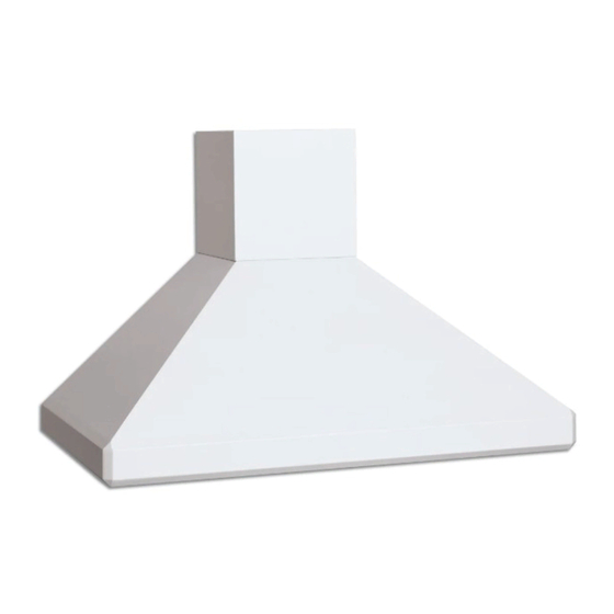
EUROLINE/EUROLINE PRO
Read All Instructions Thoroughly Before Beginning Installation
WARNING - TO REDUCE THE RISK OF FIRE, ELECTRIC SHOCK,
OR INJURY TO PERSONS, OBSERVE THE FOLLOWING:
A. Installation work and electrical wiring must be done by qualified person(s)
in accordance with all applicable codes and standards, including fire-
rated construction. Switch power off at service panel and lock the service
disconnecting means to prevent power from being switched on accidentally
during installation.
B. When cutting or drilling into wall or ceiling, do not damage electrical wiring
and other hidden utilities.
C. Ducted fans must always be vented to the outdoors.
D. Sufficient air is needed for proper combustion and exhausting of gases
through the flue (chimney) of fuel burning equipment to prevent back
drafting. Follow the heating equipment manufacturer's guideline and
safety standards such as those published by the National Fire Protection
Association (NFPA), and the American Society for Heating, Refrigeration
and Air Conditioning Engineers (ASHRAE), and local code authorities.
E. ASHRAE residential ventilation standard 62.2 limits exhaust fans (total) to
a maximum of 15 CFM per 100 square feet of occupiable space, unless a
back drafting test is performed or make-up air is provided. Consult a local
HVAC engineer for make-up air evaluation.
WARNING - TO REDUCE THE RISK OF FIRE, USE ONLY METAL
L112 1211A
WALL MOUNT HOOD
DUCTWORK
Page 1
U L
C
US
R
Advertisement

Subscribe to Our Youtube Channel
Related Manuals for Vent-a-Hood EUROLINE


Summary of Contents for Vent-a-Hood EUROLINE
-
Page 1: Installation Instructions
Read and Save These Instructions All Hoods Must Be Installed By A Qualified Installer INSTALLATION INSTRUCTIONS EUROLINE/EUROLINE PRO WALL MOUNT HOOD Read All Instructions Thoroughly Before Beginning Installation WARNING - TO REDUCE THE RISK OF FIRE, ELECTRIC SHOCK, OR INJURY TO PERSONS, OBSERVE THE FOLLOWING: A. - Page 2 20 feet, increase the duct diameter by one inch for every ten feet of duct. A 90 degree elbow is equal to 5 feet of duct. Using Vent-A-Hood roof jacks or wall louvers (back page) will ensure proper efficiency. Airflow must not be restricted at the end of the duct run. Do not use screen wire or spring-loaded doors on wall louvers or roof jacks.
-
Page 3: Installation Details
Custom hoods may require additional specification consideration. 2) When installing a 14” tall Euroline wall mount range hood, it is recommended that the bottom edge of the hood be located no more than 24” above the cooking surface for optimum performance. When installing an 18” tall Euroline Pro wall mount range hood, it is recommended that the bottom edge of the hood be located no more than 30”... - Page 4 Installation Details Continued 14” Tall Euroline Connection Diagram (30” - 48” Widths) 1 ¾” Blower 1 ⁄ ” Exhaust Wall Side Outlet Vent 6" Round 5" Hole 14" Electrical 5 ¼” 6" Outlet Centerline Of Hood 300 CFM B100 Single Blower...
- Page 5 Installation Details Continued 18” Tall Euroline Pro Connection Diagram (54”- 66” Widths) Duct Cover (Top of Hood) 12" 1 ¾” 16 ½” 5 ½” Wall Side 7 ½" 10" Dia. or 12" Dia. Transition Location 7" "Centered" 1 ¾” Electrical (2) 18"...
- Page 6 Installation Details Continued 10) Remove the screws inside the top of the back of the hood that retain the wood strip that is recessed in the mounting channel. Note: Some retaining screws may be located behind the blower(s). Remove the wood mounting strip from the back of the hood and place the top edge of the strip on the upper, level horizontal line on the wall.
- Page 7 VENTING ACCESSORIES WALL LOUVER WALL LOUVER WALL LOUVER RECTANGULAR WALL LOUVER 8 ⁄ ” 13” 11” 8 ½” 10” Back Back Back 6” 11” View View View 3 ¼” 7” 13” 6” 8” 1 ½” Flange 1 ½” Flange 1 ½” Flange MODEL DESCRIPTION MODEL...
Need help?
Do you have a question about the EUROLINE and is the answer not in the manual?
Questions and answers