Lennox 14HPX?018 Installation Instructions Manual
14hpx series units
Hide thumbs
Also See for 14HPX?018:
- Installation instructions manual (25 pages) ,
- Unit information (24 pages) ,
- Brochure & specs (2 pages)
Table of Contents
Advertisement
E2008 Lennox Industries Inc.
Dallas, Texas, USA
RETAIN THESE INSTRUCTIONS
FOR FUTURE REFERENCE
WARNING
Improper installation, adjustment, alteration, ser-
vice or maintenance can cause personal injury, loss
of life, or damage to property.
Installation and service must be performed by a
qualified installer or service agency.
CAUTION
Physical contact with metal edges and corners
while applying excessive force or rapid motion can
result in personal injury. Be aware of, and use
caution when working near these areas during
installation or while servicing this equipment.
IMPORTANT
The Clean Air Act of 1990 bans the intentional vent-
ing of refrigerant (CFC's, HFC's, and HCFC's) as of
July 1, 1992. Approved methods of recovery, recycl-
ing or reclaiming must be followed. Fines and/or in-
carceration may be levied for noncompliance.
IMPORTANT
This unit must be matched with an indoor coil as
specified in Lennox' Engineering Handbook.
Coils previously charged with HCFC−22 must be
flushed
05/08
*2P0508*
INSTALLATION
INSTRUCTIONS
14HPX Series Units
HEAT PUMP UNITS
505,243M
05/08
Supersedes 04/08
Table of Contents
. . . . . . . . . . . . . . . . . . . . . . . . . . . . . . .
. . . . . . . . . . . . . . . . . . . . . . . . . . . . . . .
. . . . . . . . . . . . . . . . . . . . . . . . . . . . . . . . . . . . .
. . . . . . . . . . . . . . . . . . . . . . . . . . . . . . . .
. . . . . . . . . . . . . . . . . . . . . . . . . . . . . . . . . .
. . . . . . . . . . . . . . . . . . . . . . . . . . . . . . . . . . .
. . . . . . . . . . . . . . . . . . . . . . . . . . . . . . . . . . . . . .
. . . . . . . . . . . . . . . . . . . . . . . . . . . . . . .
. . . . . . . . . . . . . . . . . . . . . . . . . . . . . . . . . .
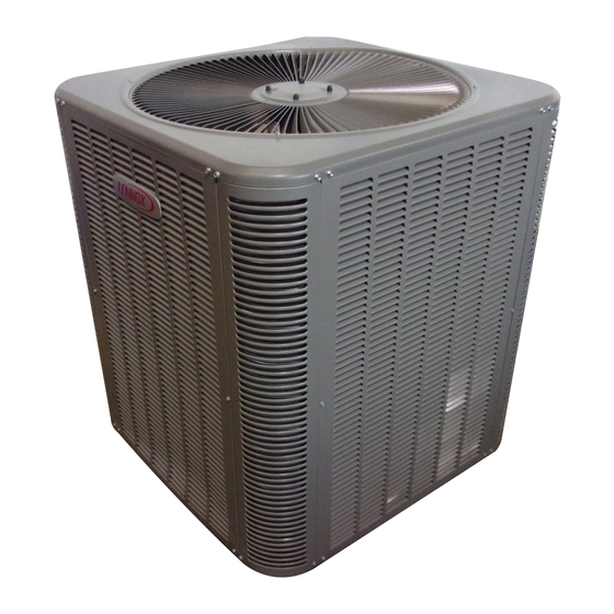
14HPX Outdoor Unit
®
14HPX Merit
outdoor units use HFC−410A refrigerant.
This unit must be installed with a matching indoor blower
coil and line set as outlined in the Lennox Engineering
Handbook. 14HPX outdoor units are designed for use in
expansion valve systems only. They are not designed to be
used with other refrigerant flow control devices. An expan-
sion valve approved for use with HFC−410A must be or-
dered separately and must be installed prior to operating
the unit.
Shipping and Packing List
1 − Assembled 14HPX outdoor unit
Check the unit components for shipping damage. If you
find any damage, immediately contact the last carrier.
Page 1
. . . . . . . . . . . . . . . . . . . . . . . . . . .
. . . . . . . . . . . . . . . . . . . . . .
. . . . . . . . . . . . . . . . . . . . . . . . . . .
. . . . . . . . . . . . . . . . . . . . . . . . . . . . .
. . . . . . . .
. . . . . . . . . . . . . . . . . . . .
. . . . . . . . . . . . . . . . . . . . . . . . . . .
. . . . . . . . . . . . . . . . . . . . . . . . . . . .
. . . . . . . . . . . . . . . . . . . . . . .
. . . . . . . . . .
. . . . . . . . . . . . . . . . . . . . . . . . . . . . .
. . . . . . . . . . . . . . . . . . . . . . . . . .
. . . . . . . . . . . . . . . . . . . . . . . .
. . . . . . . . . . . . . . . . . . . . . . . . . .
. . . . . . . . . . . . . . . . . . . . . . . . . . . . .
505,243M
*P505243M*
Litho U.S.A.
1
1
2
3
3
4
5
8
9
10
10
11
11
12
12
12
13
17
17
22
23
23
24
24
Advertisement
Table of Contents

Related Manuals for Lennox 14HPX?018


Summary of Contents for Lennox 14HPX?018
-
Page 1: Table Of Contents
This unit must be installed with a matching indoor blower The Clean Air Act of 1990 bans the intentional vent- coil and line set as outlined in the Lennox Engineering ing of refrigerant (CFC’s, HFC’s, and HCFC’s) as of Handbook. 14HPX outdoor units are designed for use in July 1, 1992. -
Page 2: Unit Dimensions
Unit Dimensions − inches (mm) 4-3/8 4-3/8 INLET AIR (111) (111) 4-3/8 4-3/8 (111) (111) OPTIONAL UNIT STAND-OFF KIT Compressor (4) (FIELD−INSTALLED) COIL DRAIN OUTLETS INLET AIR INLET AIR (AROUND PERIMETER OF BASE) 6-3/8 4-3/8 (162) VAPOR LINE CONNECTION (111) LIQUID LINE CONNECTION 6-3/8 4-3/8... -
Page 3: General Information
See figure 2. The slab should have a slope tolerance away from the Lennox Industries Inc. building of 2 degrees or 2 inches per 5 feet (51 mm per P.O. Box 799900 1524 mm). -
Page 4: Electrical
ROOF MOUNTING NOTE − To facilitate conduit, a hole is in the bottom of the control box. Connect conduit to the control box Install unit a minimum of 6 inches (152 mm) above the roof using a proper conduit fitting. surface to avoid ice build−up around the unit. -
Page 5: Refrigerant Piping
(flare or sweat connections). −036 3/8 in. 7/8 in 3/8 in. 7/8 in L15−65 Use Lennox L15 (sweat, non-flare) series line sets as (10 mm) (22 mm) (10 mm) (22 mm) 15 ft. − 50 ft. −042 (4.6 m − 15 m) shown in table 2 or use field-fabricated refrigerant lines. - Page 6 INSTALLING REFRIGERANT LINE on vertical runs. Figure 9 shows how to make a transi- tion from horizontal to vertical. Figure 10 shows how Pay close attention to line set isolation during installation of to install line sets on horizontal runs. any heat pump or a/c system.
- Page 7 ANCHORED AUTOMOTIVE HEAVY NYLON MUFFLER-TYPE WIRE TIE HANGER WALL WALL STUD STUD Strap Liquid Strap Liquid Line Line To Va- To Vapor Line por Line LIQUID LINE LIQUID LINE METAL VAPOR LINE − WRAPPED METAL VAPOR LINE − WRAPPED SLEEVE IN ARMAFLEX SLEEVE IN ARMAFLEX...
-
Page 8: Flushing Existing Line Set And Indoor Coil
Take care to empty all existing new outdoor unit. DO NOT turn on power to the unit traps. Polyol ester (POE) oils are used in Lennox or open outdoor unit service valves at this time. units charged with HFC−410A refrigerant. Residual... -
Page 9: Refrigerant Metering Device
14HPX units are used in check expansion valve (CTXV) NOTE − A single system flush should remove all of the systems only. See the Lennox Engineering Handbook for mineral oil from the existing refrigerant lines and in- approved valve match-ups and application information. -
Page 10: Manifold Gauge Set
TO ACCESS SCHRADER PORT: IMPORTANT 1. Remove service port cap with an adjustable wrench. 2. Connect gauge to the service port. Failure to remove a fixed orifice when installing an expansion valve on the indoor coil will result in 3. When testing is completed, replace service port cap and improper operation and damage to the system. -
Page 11: Leak Testing
5. Connect the manifold gauge set high pressure hose to Leak Testing the vapor valve service port. (Normally, the high pres- sure hose is connected to the liquid line port; however, After the line set has been connected to the indoor and out- connecting it to the vapor port better protects the man- door units, check the line set connections and indoor unit ifold gauge set from high pressure damage.) -
Page 12: Start−Up
matchup. Skip to the paragraph Setup for Checking and WARNING Adding Charge" on Page 13 to setup for charging and for determine if charge is needed; adjust the charge accord- Danger of Equipment Damage. Avoid deep ingly. vacuum operation. Do not use compressors to evacuate a system. -
Page 13: Setup For Checking And Adding Charge
Step 1. Determine the desired DT Measure entering air tempera- Temp. ture using dry bulb (A) and wet bulb (B). DT is the intersecting value of 24 24 24 23 23 22 22 22 20 19 18 17 16 15 of air entering A and B in the table (see triangle). - Page 14 WEIGH IN 1. Check Liquid and suction line pressures 2. Compare unit pressures with table 12, Normal Operating Pressures. Refrigerant Charge per Line Set Length 3. Conduct leak check; evacuate previously outlined. 4. Weigh in the unit nameplate charge plus Ounces per 5 feet (g per 1.5 m) Liquid Line any charge required for line set differences...
- Page 15 Table 4. 14HPX−018 Target *Add Subcooling charge Target INDOOR MATCHUPS *Add Heat Heat Cool Cool Subcooling charge (+5ºF) (+1ºF) INDOOR MATCHUPS Heat Heat Cool Cool 14HPX−036 (Continued) (+5ºF) (+1ºF) CR33−50/60C CBX27UH−018/024 CR33−48B/C CBX32MV−018/024 CX34−49C Table 5. 14HPX−024 CX34−43B/C, −50/60C Target *Add CX34−38A/B S/N# 6007 and after Subcooling...
- Page 16 Table 11. Normal Operating Pressures − Liquid +10 & Vapor +5 PSIG* IMPORTANT Use table 11 as a general guide when performing maintenance checks. This is not a procedure for charging the unit (Refer to Charging / Checking Charge section). Minor variations in these pressures may be expected due to differences in installations.
-
Page 17: System Operation
Table 12. HFC−410A Temp. (°F) − Pressure (Psig) The 14HPX is equipped with an auto-reset high pressure switch (single−pole, single−throw) which is located on the °F Psig °F Psig °F Psig °F Psig liquid line. The switch shuts off the compressor when dis- −40 10.1 80.5... - Page 18 (OPTIONAL) Low Pressure Switch (LO−PS) When the Table 13. Sensor Temp. / Resistance Range low pressure switch trips, the defrost board will cycle off the Temperature Resistance values Pins/Wire compressor, and the strike counter in the board will count Range °F (°C) range (ohms) Color Sensor...
- Page 19 AMBIENT SENSOR Figure 21. Sensor Locations Ambient Sensor The ambient sensor (shown in figure Defrost Temperature Termination Shunt (Jumper) 21) considers outdoor temperatures below −35°F (−37°C) Pins The defrost board selections are: 50, 70, 90, and or above 120°F (48°C) as a fault. If the ambient sensor is 100°F (10, 21, 32 and 38°C).
- Page 20 OPERATIONAL DESCRIPTION Calibration success depends on stable system tempera- tures during the 20−minute calibration period. If the board The defrost control board has three basic operational fails to calibrate, another defrost cycle will be initiated after modes: normal, calibration, and defrost. 45 minutes of heating mode compressor run time.
- Page 21 Y1 Active ( 0" line inactive) Short test pins for longer Short test pins for more than 2 seconds than 1 second but less than 2 seconds Clear any short cycle lockout and 5 strike fault lockout function, if applicable. Clear any short cycle lockout If in COOLING Mode If in HEATING Mode...
-
Page 22: Maintenance
Table 14. Defrost Control Board Diagnostic LEDs Green Condition/Code Possible Cause(s) Solution Power problem No power (24V) to board termi- Check control transformer power (24V). nals R & C or board failure. If power is available to board and LED(s) do not light, replace board. -
Page 23: Optional Accessories
Your new Lennox heat pump has several characteristics that you should be aware of: 1. Ask your Lennox dealer to show you where your indoor unit’s filter is located. It will be either at the indoor unit Heat pumps satisfy heating demand by delivering (installed internal or external to the cabinet) or behind large amounts of warm air into the living space. -
Page 24: Thermostat Operation
Temperature indicator displays actual room temperature. PROGRAMMABLE THERMOSTATS Thermostat Operation Your Lennox system may be controlled by a program- Though your thermostat may vary somewhat from the de- mable thermostat. These thermostats provide the added scription below, its operation will be similar.
Need help?
Do you have a question about the 14HPX?018 and is the answer not in the manual?
Questions and answers
Do I need to replace the entire reversing valve if just the solenoid is bad?
You can replace just the solenoid on a Lennox 14HPX-018 reversing valve. The valve itself requires no maintenance, and the solenoid is the only replaceable part. If the valve itself fails, then the entire valve must be replaced.
This answer is automatically generated