Advertisement
Service Literature
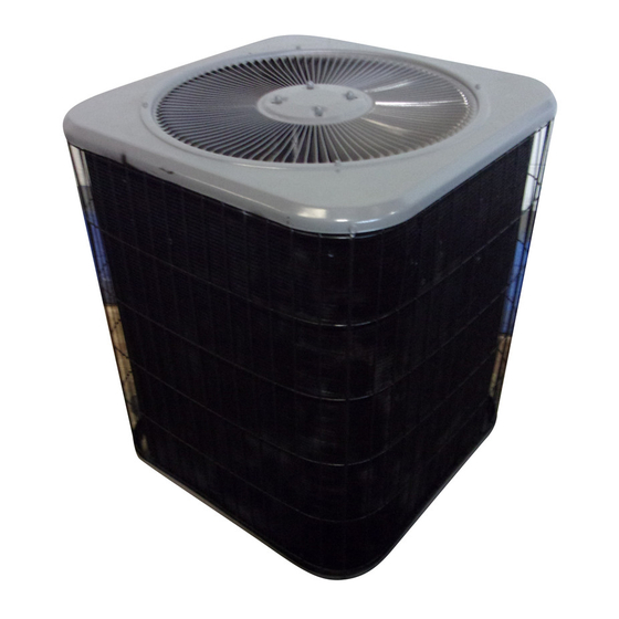
The 10ACC is a residential split-system condensing
unit available in sizes ranging from 1-1/2 to 5 tons. Con-
densing coil size, circuiting and air volume result in a
minimum SEER rating of 10.0. The series is designed
for use with an expansion valve or RFCIV system in the
indoor unit.
10ACC 1-1/2 to 3 ton units are equipped with reciprocating
compressors. All compressors are hermetically sealed for
long service life. The compressor is installed in the unit on re-
silient rubber mounts to assure quiet, vibration-free operation.
A built-in protection device assures protection from excessive
current and temperatures.
10ACC 3-1/2 to 5 ton units are equipped with scroll com-
pressors. The scroll operates like a standard compressor but
it is unique in the way it compresses refrigerant.
WARNING
Refrigerant can be harmful if it is inhaled. Refriger-
ant must be used and recovered responsibly.
Failure to follow this warning may result in person-
al injury or death.
WARNING
Electric shock hazard. Can cause injury
or death. Before attempting to perform
any service or maintenance, turn the
electrical power to unit OFF at discon-
nect switch(es). Unit may have multiple
power supplies.
10ACC SERIES UNITS
This manual is divided into sections which discuss the
major components, refrigerant system, charging proce-
dure, maintenance and operation sequence.
All specifications in this manual are subject to change.
Improper installation, adjustment, alteration, ser-
vice or maintenance can cause property damage,
personal injury or loss of life. Installation and ser-
vice must be performed by a qualified installer or
service
Page 1
IMPORTANT
agency.
10ACC
Corp. 0201-L1
ã 2002 Lennox Industries Inc.
Litho U.S.A.
Advertisement
Table of Contents

Related Manuals for Lennox 10ACC Series


Summary of Contents for Lennox 10ACC Series
- Page 1 OFF at discon- personal injury or loss of life. Installation and ser- nect switch(es). Unit may have multiple vice must be performed by a qualified installer or power supplies. service agency. Page 1 ã 2002 Lennox Industries Inc. Litho U.S.A.
-
Page 2: Electrical Data
ELECTRICAL DATA General Model No. 10ACC-018 10ACC-024 10ACC-030 10ACC-036 10ACC-042 10ACC-048 10ACC-060 Data -230 -230 -230 -230 -230 -230 -230 Line voltage data - 60hz 208/230v-1ph 208/230v-1ph 208/230v-1ph 208/230v-1ph 208/230v-1ph 208/230v-1ph 208/230v-1ph Rec. max fuse size (amps) ¡Minimum circuit ampacity 11.6 14.3 17.3... -
Page 3: Unit Components
All major components (indoor blower and coil) must be RELAY (K31) (option only) matched according to Lennox recommendations for the com- pressor to be covered under warranty. Refer to the Engineer- GROUNDING ing Handbook for approved system matchups. A misapplied system will cause erratic operation and can result in early compressor failure. - Page 4 2 - Dual Capacitor C12 Electrical openings are provided under the control box cov- The compressor and fan in 10ACC series units use per- er. Field thermostat wiring is made to color-coded pigtail manent split capacitor motors. The capacitor is located connections.
-
Page 5: Scroll Compressor
If the properties. Figure 5 shows the basic scroll form. Two iden- compressor is replaced, conventional Lennox cleanup tical scrolls are mated together forming concentric spiral practices must be used. - Page 6 HOW A SCROLL WORKS SUCTION MOVEMENT OF ORBIT SUCTION INTERMEDIATE PRESSURE CRESCENT SHAPED GAS POCKET ORBITING SCROLL SUCTION POCKET FLANKS SEALED BY CENTRIFUGAL STATIONARY SCROLL FORCE SUCTION SUCTION HIGH DISCHARGE PRESSURE POCKET FIGURE 7 C - Condenser Fan Motor CONDENSER FAN MOTOR AND COMPRESSOR ACCESS All units use single-phase PSC fan motors which require a run capacitor.
-
Page 7: Refrigerant System
(sweat connections) to the indoor liquid line and 5/16 for suction line), turn stem clockwise evaporator coil (flare or sweat connections). Use Lennox to seat the valve. Tighten firmly. L10 (flare) or L15 (sweat, non-flare) series line sets as 3 - Replace stem cap. - Page 8 SUCTION LINE (BALL TYPE) SERVICE VALVE SUCTION LINE SERVICE VALVE (VALVE OPEN) (VALVE OPEN) USE ADJUSTABLE WRENCH INSERT HEX ROTATE STEM CLOCKWISE 90_ TO CLOSE WRENCH HERE STEM CAP ROTATE STEM COUNTER-CLOCKWISE 90_ TO OPEN INLET (TO STEM CAP INDOOR COIL) INLET (FROM INDOOR COIL) STEM...
- Page 9 D - Charging CAUTION Units are factory charged with the amount of HCFC-22 re- When using dry nitrogen, a pressure reducing reg- frigerant indicated on the unit nameplate. This charge is ulator must be used to prevent excessive pres- based on a matching indoor coil and outdoor coil with a 20 sure in gauge manifold, connecting hoses, and ft.
- Page 10 Weighing in the Charge Fixed Orifice or Table 3 10ACC Subcooling Values TXV Systems – Outdoor Temp < 60_F (16_C) (Fixed Orifice Systems Only) If the system is void of refrigerant, or if the outdoor ambient OUTDOOR LIQUID SUBCOOLING [+ 1_F (.6_C)] temperature is cool, the refrigerant charge should be TEMP.
-
Page 11: Evaporator Coil
Table 5 Normal Operating Pressures In psig (liquid and suction +/- 2 psig)* Out. Coil -018 -024 -030 -036 -042 -048 -060 Unit / Entering Entering Metering Metering Air Temp. Device LIQ. SUC. LIQ. SUC. LIQ. SUC. LIQ. SUC. LIQ. SUC. - Page 12 V - WIRING DIAGRAMS AND SEQUENCE OF OPERATION 10ACC OPERATING SEQUENCE NOTE- The thermostat used may be electromechanical or electronic. NOTE- Transformer in indoor unit supplies power (24 VAC) to the thermostat and outdoor unit controls. COOLING: 1 - Cooling demand initiates at Y1 in the thermostat. 2 - 24VAC energizes compressor contactor K1.
Need help?
Do you have a question about the 10ACC Series and is the answer not in the manual?
Questions and answers