Lennox Merit 14HPX Installation Instructions Manual
Hide thumbs
Also See for Merit 14HPX:
- Installation instructions manual (29 pages) ,
- Unit information (24 pages) ,
- Brochure & specs (2 pages)
Table of Contents
Advertisement
E2011 Lennox Industries Inc.
Dallas, Texas, USA
RETAIN THESE INSTRUCTIONS
FOR FUTURE REFERENCE
These instructions are intended as a general guide and do
not supersede local codes in any way. Consult authorities
having jurisdiction before installation.
WARNING
Improper installation, adjustment, alteration, service or
maintenance can cause personal injury, loss of life, or
damage to property.
Installation and service must be performed by a licensed
professional installer (or equivalent) or a service agency.
IMPORTANT
The Clean Air Act of 1990 bans the intentional venting of
refrigerant (CFCs, HCFCs and HFCs) as of July 1, 1992.
Approved methods of recovery, recycling or reclaiming
must be followed. Fines and/or incarceration may be
levied for noncompliance.
IMPORTANT
This unit must be matched with an indoor coil as
specified in Lennox Engineering Handbook. Coils
previously charged with HCFC−22 must be flushed.
NOTICE TO INSTALLER
UNIT PLACEMENT
It is critical for proper unit operation to place outdoor unit on an
elevated surface as described in Unit Placement section on page 7.
DEFROST OPERATION
It is critical for proper defrost operation to set the defrost termination
pins (P1) on the defrost control prior to starting system. See Defrost
System section on page 29 for further details.
BRAZING LINE SET TO SERVICE VALVES
It is imperative to follow the brazing technique illustrated starting on
page 12 to avoid damaging the service valve's internal seals.
02/11
*2P0211*
INSTALLATION
INSTRUCTIONS
®
Merit
Series 14HPX Units
HEAT PUMP UNITS
506649−01
02/11
Supersedes 11/10
TABLE OF CONTENTS
. . . . . . . . . . . . . . . . . . . . . . . . . . . . . . . . . . . . . . . .
. . . . . . . . . . . . . . . . . . . . . . . . . . . . . . . . .
. . . . . . . . . . . . . . . . . . . . . . . . . . . . . . . . . . . . . . .
. . . . . . . . . . . . . . . . . . . . . . . . . . . . . . . .
. . . . . . . . . . . . . . . . . . . . . . . . . . . . . . . . . . .
Shipping and Packing List
Check the unit components for shipping damage. If you
find any damage, immediately contact the last carrier.
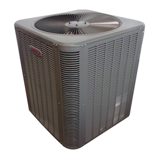
1
Assembled 14HPX outdoor unit
General
®
The Merit
14HPX model is designed for use with
HFC−410A refrigerant only. This unit must be installed with
an approved indoor air handler or coil. See the Lennox
14HPX Engineering Handbook for approved indoor
component matchups.
IMPORTANT
This model is designed for use in expansion valve
systems only. An indoor expansion valve approved for
use with
HFC−410A
separately, and installed prior to operating the system.
Page 1
. . . . . . . . . . . . . . . . . . . . . . . .
. . . . . . . . . . . . . . . . . . . . . .
. . . . . . . . . . . . . . . . . . .
. . . . . . . . . . .
. . . . . . . . . . . . . . . . . . . . . . . . . . . . .
. . . . . . . . . . . . . . . . . . . . .
. . . . . . . . . . . . . . . . . .
. . . . . . . . . . . . . . . . . . . . . . . . . . .
. . . . . . . . . . . . . . . .
. . . . . . . . . . . . . . . .
. . . . . . . . . . . . . . .
. . . . . . . . . . . . .
. . . . . . . . . . . . . . . . . . . . . . . . . .
. . . . . . . . . . .
. . . . . . . . . . . . . . . . . . . . . . . . . . . . .
. . . . . . . . . . . . . . . . . . . . . . . . . . . . . .
. . . . . . . . . . . . . .
refrigerant must be ordered
506649−01
*P506649-01*
Litho U.S.A.
1
1
2
2
3
4
. . . . . . .
6
7
7
9
12
15
16
17
18
19
24
24
24
28
29
35
36
Advertisement
Table of Contents

Related Manuals for Lennox Merit 14HPX


Summary of Contents for Lennox Merit 14HPX
-
Page 1: Table Of Contents
HFC−410A refrigerant only. This unit must be installed with UNIT PLACEMENT an approved indoor air handler or coil. See the Lennox It is critical for proper unit operation to place outdoor unit on an 14HPX Engineering Handbook for approved indoor elevated surface as described in Unit Placement section on page 7. -
Page 2: Unit Dimensions
Unit Dimensions − inches (mm) DISCHARGE AIR OUTDOOR COIL FAN COMPRESSOR SUCTION AND LIQUID LINE CONNECTION OPTIONAL UNIT STANDOFF KIT (4) (FIELD INSTALLED) SIDE VIEW SIDE VIEW Model Number 14HPX−018−230 24−1/4 (616) 29−1/4 (743) 28−1/2 (724) 14HPX−024−230 24−1/4 (616) 29−1/4 (743) 28−1/2 (724) 14HPX−030−230 24−1/4 (616) -
Page 3: Typical Unit Parts Arrangement
Typical Unit Parts Arrangement THERMAL PROTECTION SWITCH (S173) (ONLY ON CONTROL BOX COMPRESSORS USING EXTERNAL DUAL RUN COMPRESS0R PROTECTION) CAPACITOR (C12) SWITCH DISCHARGE COVER LINE CONTACTOR (K1) DISTRIBUTOR MUFFLER GROUND CHECK EXPANSION VALVE REVERSING VALVE (L1) DEFROST EQUALIZER LINE CONTROL (A108) BI−FLOW FILTER DRIER... -
Page 4: Operating Gauge Set And Service Valves
Each valve is equipped with a service port which has a recess. factory−installed valve stem. Figure 2 provides information See the Lennox Service and Application Notes #C−08−1 on how to access and operating both angle and ball service for further details and information. - Page 5 Operating Angle Type Service Valve: 1. Remove stem cap with an appropriately sized wrench. 2. Use a service wrench with a hex−head extension (3/16" for liquid line valve sizes and 5/16" for vapor line valve sizes) to back the stem out counterclockwise as far as it will go. SERVICE PORT CAP SERVICE PORT CORE (VALVE STEM SHOWN...
-
Page 6: Recovering Refrigerant From Existing System
Recovering Refrigerant from Existing System RECOVERING REFRIGERANT FROM SYSTEM DISCONNECT POWER CONNECT MANIFOLD GAUGE SET Disconnect all power to the existing outdoor unit at the service Connect a gauge set, clean recovery cylinder and a recovery disconnect switch or main fuse box/breaker panel. machine to the service ports of the existing unit. -
Page 7: New Unit Placement
MINIMUM CLEARANCE CLEARANCE ON ALL SIDES INCHES (MILLIMETERS) ABOVE UNIT 6 (152) ACCESS PANEL NOTES: 48 (1219) Clearance to one of the other three sides must be 36 inches (914mm). 30 (762) 12 (305) Clearance to one of the remaining two sides may be 12 inches (305mm) and the final side may be 6 inches (152mm). - Page 8 INSTALL UNIT AWAY DETAIL B DETAIL A FROM WINDOWS These units operate under a wide range of weather conditions; therefore, several factors must be considered when positioning the outdoor unit. The unit must be positioned to give adequate clearances for sufficient airflow and servicing. Install unit level or, if on a slope, maintain slope tolerance of 2 degrees (or 2 inches per 5 feet [50 mm per 1.5 m]) away from building structure.
-
Page 9: Removing And Installing Louvers
Removing and Installing Louvers WARNING To prevent personal injury, or damage to panels, unit or structure, be sure to observe the following: While installing or servicing this unit, carefully stow all removed panels out of the way, so that the panels will not cause injury to personnel, nor cause damage to objects or structures nearby, nor will the panels be subjected to damage (e.g., being bent or scratched). - Page 10 Field refrigerant piping consists of liquid and suction lines from the outdoor unit (braze connections) to the indoor unit IMPORTANT coil (flare or braze connections). Use Lennox L15 (braze, non−flare) series line set, or use field−fabricated refrigerant lines as listed in table 2.
- Page 11 LINE SET IMPORTANT Refrigerant lines must not contact structure. INSTALLATION REFRIGERANT LINE SET INSTALLING Line Set Isolation The following illustrations are VERTICAL RUNS (NEW CONSTRUCTION SHOWN) examples of proper refrigerant line set isolation: NOTE Insulate liquid line when it is routed through areas where the surrounding ambient temperature could become higher than the REFRIGERANT LINE SET TRANSITION...
-
Page 12: Brazing Connections
Brazing Connections IMPORTANT Use the procedures outline in figures 8 and 9 for brazing line set connections to service valves. Connect gauge set low pressure side to vapor line service valve and repeat procedure starting at IMPORTANT paragraph 4 for brazing the liquid line to service port valve. - Page 13 CAP AND CORE REMOVAL CUT AND DEBUR Cut ends of the refrigerant lines square (free from nicks or dents) Remove service cap and core from and debur the ends. The pipe must remain round. Do not crimp end both the suction / vapor and liquid line of the line.
- Page 14 WRAP SERVICE VALVES To help protect service valve seals during brazing, wrap water saturated cloths around service valve bodies and copper tube stubs. Use additional water saturated cloths underneath the valve body to protect the base paint. FLOW NITROGEN Flow regulated nitrogen (at 1 to 2 psig) through the refrigeration gauge set into the valve stem port connection on the liquid service valve and out of the suction / vapor valve stem port.
-
Page 15: Flushing Line Set And Indoor Coil
Flushing Line Set and Indoor Coil Flushing is only required if existing indoor coil and line set are to be used. Otherwise proceed to Installing Indoor Metering Device on page 16. TYPICAL EXISTING FIXED ORIFICE TYPICAL EXISTING EXPANSION VALVE REMOVAL REMOVAL PROCEDURE (UNCASED PROCEDURE (UNCASED COIL SHOWN) COIL SHOWN) -
Page 16: Installing Indoor Metering Device
Refer to below illustration for reference during installation of expansion valve unit. . See the Lennox 14HPX Engineering Handbook for approved expansion valve kit match ups. The expansion After installation of the indoor coil metering device, valve unit can be installed internal or external to the indoor proceed to Leak Test Line Set and Indoor Coil on page 17. -
Page 17: Leak Test Line Set And Indoor Coil
Take down to 1 or 2 psig (6.9 to 13.8 kPa). care to empty all existing traps. Polyol ester (POE) oils are used in Lennox units charged with HFC−410A WARNING refrigerant. Residual mineral oil can act as an insulator, preventing proper heat transfer. -
Page 18: Evacuating Line Set And Indoor Coil
Evacuating Line Set and Indoor Coil CONNECT GAUGE SET HIGH NOTE Remove cores from service valves (if not already done). Connect low side of manifold gauge set with 1/4 SAE in−line tee to vapor line service valve OUTDOOR MANIFOLD A34000 1/4 SAE TEE WITH UNIT GAUGE SET Connect high side of manifold gauge... -
Page 19: Electrical Connections
defined as any gas that will not condense under WARNING temperatures and pressures present during operation of an air conditioning system. Non−condensables and water Danger of Equipment Damage. Avoid deep vacuum suction combine with refrigerant to produce substances operation. Do not use compressors to evacuate a that corrode copper piping and compressor parts. - Page 20 ROUTING HIGH VOLTAGE/ GROUND AND CONTROL WIRING HIGH VOLTAGE / GROUND WIRES Any excess high voltage field wiring should be trimmed and secured away from any low voltage field wiring. To facilitate a conduit, a cutout is located in the bottom of the control panel. Connect conduit to the control panel using a proper conduit fitting. TYPICAL CONTROL WIRING LOW VOLTAGE CONTROL WIRING Install low voltage wiring from outdoor to indoor unit and from...
- Page 21 Figure 15. Typical Field Wiring Diagram Page 21 14HPX SERIES...
- Page 22 HIGH PRESSURE AMBIENT SENSOR SWITCH (S4) LIQUID (RT13) LINE REVERSING VALVE (L1) COIL SENSOR (RT21) CRANKCASE HEATER (HR1) CRANKCASE THERMOSTAT (S40) (−036 THROUGH − 060 UNITS ONLY Figure 16. Typical Factory Wiring Diagram Page 22 506649−01...
- Page 23 THERMAL SWITCH (S173) HIGH PRESSURE AMBIENT SENSOR SWITCH (S4) LIQUID (RT13) LINE REVERSING VALVE (L1) COIL SENSOR (RT21) CRANKCASE HEATER (HR1) CRANKCASE THERMOSTAT (S40) (−036 THROUGH − 060 UNITS ONLY Figure 17. Typical Factory Wiring Diagram (Compressors using External Thermal Protection S173) Page 23 14HPX SERIES...
-
Page 24: Servicing Unit Delivered Void Of Charge
3. After evacuation is complete, open the liquid line and Servicing Units Delivered Void of Charge suction line service valves to release the refrigerant charge (contained in outdoor unit) into the system. If the outdoor unit is void of refrigerant, clean the system using the procedure described below. - Page 25 CHECKING AIR FLOW AT INDOOR COIL 1. Temperature rise between the return air and supply air temperatures at the indoor coil blower unit, Cooling Mode Indoor Airflow Check 2. Measuring voltage supplied to the unit, Check airflow using the Delta−T ( process using figure 3.
- Page 26 Check the airflow as illustrated in figure 19 to be sure the indoor airflow is as required. (Make any air flow SUBCOOLING adjustments before continuing with the following procedure.) Measure outdoor ambient temperature; determine whether to use cooling mode or heating mode to check charge.
- Page 27 Table 4 − Indoor Units Matchups and Subcooling Charge Levels Target Target Target *Add *Add *Add Subcooling Subcooling Subcooling INDOOR MATCHUPS INDOOR MATCHUPS INDOOR MATCHUPS charge charge charge Heating Cooling Heating Cooling Heating Cooling (+5ºF) (+1ºF) (+5ºF) (+1ºF) (+5ºF) (+1ºF) 14HPX−030−230 14HPX−018−230 14HPX−042−230 (Continued)
-
Page 28: System Operation
Table 5. Normal Operating Pressures − Liquid +10 and Vapor +5 PSIG* IMPORTANT Use table 5 as a general guide when performing maintenance checks. This is not a procedure for charging the unit (Refer to Charging / Checking Charge section). Minor variations in these pressures may be expected due to differences in instal- lations. -
Page 29: Defrost System
Coil Sensor (RT21) NOTE − The demand defrost control accurately measures the performance of the system as frost accumulates on the The coil temperature sensor (shown in figure 1) considers outdoor coil. This typically will translate into longer running outdoor temperatures below −35°F (−37°C) or above 120°F time between defrost cycles as more frost accumulates on (48°C) as a fault. - Page 30 NOTE Within a single room thermostat demand, if DETAILED DEFROST SYSTEM OPERATION 5−strikes occur, the defrost control will lockout the unit. Defrost Cycles Demand defrost control’s 24 volt power R must be cycled The demand defrost control initiates a defrost cycle based OFF or the TEST pins on defrost control must be shorted on either frost detection or time.
- Page 31 Line output 24VAC service light output. 24VAC typically used to supply power to the Lennox System Operation Monitor 24 Volt output (LSOM) Page 31 14HPX SERIES...
- Page 32 DEMAND DEFROST CONTROL DIAGNOSTICS Table 8. Demand Defrost Control Diagnostic LEDs Green Condition/Code Possible Cause(s) Solution Power problem No power (24V) to demand defrost Check control transformer power (24V). control terminals R & C or defrost con- If power is available to defrost control and LED(s) do trol failure.
- Page 33 Table 9. Ambient (RT13) and Coil (RT21) Sensors Temperature / Resistance Range Degrees Degrees Degrees Degrees Resistance Resistance Resistance Resistance Fahrenheit Fahrenheit Fahrenheit Fahrenheit 136.3 2680 56.8 16657 21.6 44154 −11.3 123152 133.1 2859 56.0 16973 21.0 44851 −11.9 125787 130.1 3040 55.3...
- Page 34 TEST Placing the jumper on the field test pins allows the technician to: Clear short cycle lockout Clear five−strike fault lockout Cycle the unit in and out of defrost mode Place the unit in defrost mode to clear the coil When Y1 is energized and 24V power is being applied to the Control, a test cycle can be initiated by placing a jumper on the Control’s TEST pins for 2 to 5 seconds.
-
Page 35: Maintenance
2. Lennox blower motors prelubricated Ask your Lennox dealer to show you where Air Filter permanently sealed. No more lubrication is needed. your indoor unit’s filter is located. It will be either at the indoor unit (installed internal or external to the cabinet) 3. -
Page 36: Start−Up And Performance Checklist
After a six-hour compressor crankcase warm-up Heat Pump Operation period, the thermostat can be switched to the HEAT setting Your new Lennox heat pump has several characteristics and normal heat pump operation may resume. that you should be aware of:...
Need help?
Do you have a question about the Merit 14HPX and is the answer not in the manual?
Questions and answers