Table of Contents
Advertisement
Quick Links
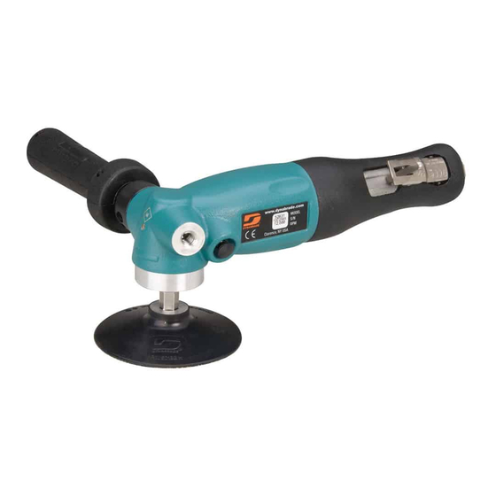
4", 5" Right Angle Sanders
Model
Wheel Size
52631
4"
52634
4-1/2"
52635
5"
FIND THE MOST CURRENT OFFERING OF SUPPORT DOCUMENTS AND ACCESSORIES @ WWW.DYNABRADE.COM
Read and understand this tool manual before operating your air tool. Follow all safety rules for the protection of operating personnel
as well as adjacent areas. Always operate, inspect and maintain this tool in accordance with the American National Standards
Institute (ANSI) Safety Code for Portable Air Tools – B186.1. For additional safety information, refer to Safety Requirements for the
Use, Care and Protection of Abrasive Wheels – ANSI B7.1, Code of Federal Regulation – CFR 29 Part 1910, European Committee for
Standards (EN) Hand Held Non-Electric Power Tools – Safety Requirements and applicable State and Local Regulations.
Read and understand tool manual before
work starts to reduce risk of injury to
operator, visitors, and tool.
Eye protection must be worn at all times,
eye protection to conform to ANSI Z87.1.
Respiratory protection to be used when exposed to
contaminants that exceed the applicable threshold
limit values required by law.
Some dust created by grinding, sanding, drilling, and other construction activities contain chemicals known to cause cancer, birth
defects or other reproductive harm. Some examples of these chemicals are:
• Lead from lead-based paints
• Crystalline silica from bricks and cement and other masonry products
• Arsenic and chromium from chemically treated lumber
Your risk from these exposures varies, depending on how often you do this type of work. To reduce your exposure to these chemicals: work in a well
ventilated area, and work with approved safety equipment, such as those dust masks that are specially designed to filter out microscopic particles.
Carefully Read all instructions before operating or servicing any Dynabrade
Products offered by Dynabrade are not to be modified, converted or otherwise altered from the original design without expressed written consent from Dynabrade, Inc.
Tool Intent: 4"- 5" Right Angle Sanders are ideal for material removal using abrasive discs with appropriate back-up pads.
This power tool is not intended for use in potentially explosive atmospheres and is not insulated against contact with electrical power.
Training: Proper care, maintenance, and storage of your air tools will maximize their performance.
• Employer's Responsibility – Provide 4"- 5" Right Angle Sander operators with safety instructions and training for safe use of tools and accessories.
Accessory Selection:
• Warning: DO NOT use cut-off wheels, saw blades, grinding wheels or flap discs. See tool intent for recommended accessory.
• Follow tool specifications chart before choosing size and type of accessory.
• Back-up Pad/Abrasive RPM (speed) rating MUST be approved for AT LEAST the tool RPM rating.
• Only use recommended fittings and air line sizes. Air supply hoses and air hose accessories must have a minimum working pressure of 150 PSIG (10 Bars, g) or 150 percent of the maximum
pressure produced in the system, whichever is higher. (See Machine Specifications table on back cover.)
Air Tool Manual – Safety, Operation and Maintenance
SAVE THIS DOCUMENT, EDUCATE ALL PERSONNEL
RPM
Spindle Thread
12,000
3/8"- 24
12,000
5/8"-11
12,000
5/8"-11
WARNING
SAFETY LEGEND
WARNING
WARNING
WARNING
SAFETY INSTRUCTIONS
®
Abrasive Power Tool.
Do Not Use Tool For Anything Other Than Its Intended Applications.
(continued on next page)
Practice safety requirements. Work alert,
have proper attire, and do not operate tools under
the influence of alcohol or drugs.
Ear protection to be worn when exposure to sound,
exceeds the limits of applicable Federal, State or
local statues, ordinances and/or regulations.
Air line hazard, pressurized supply lines and flexible
hoses can cause serious injury. Do not use damaged,
frayed or deteriorated air hoses and fittings.
WARNING
Parts Page Reorder No. PD07•39
Effective December, 2007
Model 52634
Shown
WARNING
WARNING
WARNING
Advertisement
Table of Contents

Subscribe to Our Youtube Channel
Related Manuals for Dynabrade 52631


Summary of Contents for Dynabrade 52631
- Page 1 Abrasive Power Tool. Products offered by Dynabrade are not to be modified, converted or otherwise altered from the original design without expressed written consent from Dynabrade, Inc. Tool Intent: 4"- 5" Right Angle Sanders are ideal for material removal using abrasive discs with appropriate back-up pads.
-
Page 2: Air System
Spindle end should be flush with locking flange nut with Optional Spacer(s) + or - 1/16". Spacers may be needed to achieve ideal mounting. • For model 52631 – Thread back-up pad onto spindle securely. Back-Up Pad • Check mounting by rotating spindle, make certain abrasive disc is concentrically mounted and back-up pad is not excessively warped. - Page 3 • Refer to Dynabrade's Warning/Safety Operating Instructions Tag (Reorder No. 95903) for safety information. After maintenance is performed on tool, add a few drops of Dynabrade Air Lube (P/N 95842) to the air line and start the tool a few times to lubricate air motor.
- Page 4 = Air Lube 25265 Retainer 53609 Felt Seal Wicking: W = Gear Oil 3 Spindles 25268 3/8-24" - Mdl 52631 25271 5/8-11" - Mdls 52634, 52635 Adhesive: A = Loctite #609 01036 Bearing = Loctite #380 98288 Shim (as required)
- Page 5 Note: Rotating the valve stem while inserting prevents damage to the o-ring 2. Apply several drops of the Dynabrade Air Lube 10W/NR (P/N 95842 or equivalent) to valve seat pocket wall on the inside of the 25245 Throttle Handle before inserting the 51945 Valve Seat.
-
Page 6: Final Assembly
Follow these steps to verify the correct rated operating speed of the tool. 1. Supply 3 drops of 95482 Dynabrade Air Lube 10W/NR (or equivalent) into the air inlet bushing of the tool while the throttle lever is depressed. Allowing the oil to flow into the air motor. - Page 7 This service chart is published as a guide to expectant life of component parts. The replacement levels are based on average tool usage over one year. Dynabrade Inc. considers one year usage to be 1,000 hours. Parts Common to all Models:...
-
Page 8: Optional Accessories
Visit Our Web Site: www.dynabrade.com Email: Customer.Service@Dynabrade.com DYNABRADE, INC., 8989 Sheridan Drive • Clarence, NY 14031-1490 • Phone: (716) 631-0100 • Fax: 716-631-2073 • International Fax: 716-631-2524 DYNABRADE EUROPE S.àr.l., Zone Artisanale • L-5485 Wormeldange—Haut, Luxembourg • Telephone: 352 76 84 94 1 • Fax: 352 76 84 95 1 ©...
Need help?
Do you have a question about the 52631 and is the answer not in the manual?
Questions and answers