Table of Contents
Advertisement
Advertisement
Table of Contents

Subscribe to Our Youtube Channel
Related Manuals for Dimplex A12M


Summary of Contents for Dimplex A12M
- Page 1 A Class Air Source Heat Pump A12M / A16M: Installation Manual 8/60472/0 Issue 1...
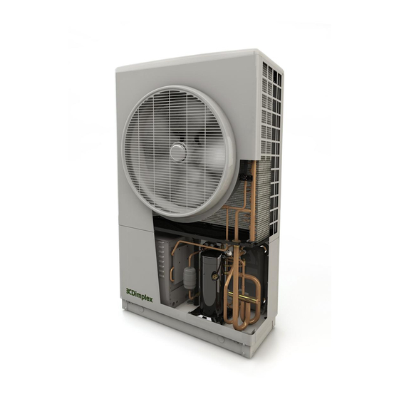
- Page 2 Overall view Figure 1 (a): Outer dimensions of heat pump, (b) position of heat pump registration plate and details (c) Internal components of heat pump...
-
Page 3: Table Of Contents
Contents 1 Introduction ..................1 2 Scope of delivery ................... 1 3 Pre-Installation advice ................5 3.1 Warnings ..................5 3.2 Intended use ..................6 3.3 Legal ....................6 3.4 Heat pump sizing ................6 3.5 Site selection ..................6 3.5.1 Location of heat pump .............. - Page 4 7 Commissioning ..................20 7.1.1 Waterside check................20 7.1.2 Temperature check ..............21 7.1.3 Electrical connections (SH) ............21 7.1.4 Water flow check ................ 21 7.1.5 DHW setup ................. 22 7.1.6 Electrical connections (DHW) ............22 7.1.7 DHW Test................... 22 7.1.8 Disinfection ................
-
Page 5: Introduction
1 Introduction To install the heat pump for space heating and domestic hot water but not using an A class cylinder you Thank you for choosing a Dimplex Heat must purchase Pack which Pump. The Dimplex A class heat pump... - Page 6 PACK 1: SPACE HEATING AND DIMPLEX A CLASS CYLINDER Heat pump A12M / A16M Hydraulics Kit A which includes: ACCHYPK User interface (UI) 049179 Pump - UPM GEO 25-85 180 (70mm cable) 049148 2 x Pump Valve Gate 1"1/2 – 28mm 2 x Washer 30.1x21x2mm...
- Page 7 PACK 2: SPACE HEATING AND DIMPLEX STANDARD HEAT PUMP CYLINDER Heat pump A12M / A16M Hydraulics Pack A which includes: ACCHYPK User interface (UI) 049179 Pump - UPM GEO 25-85 180 (70mm cable) 049148 2 x Pump Valve Gate 1"1/2 – 28mm 2 x Washer 30.1x21x2mm...
- Page 8 PACK 3: SPACE HEATING ONLY Heat pump A12M / A16M Hydraulics Pack B which includes: ACSSHYPK User interface (UI) 049179 Pump - UPM GEO 25-85 180 (70mm cable) 049148 2 x Pump Valve Gate 1"1/2 – 28mm 2 x Washer 30.1x21x2mm...
-
Page 9: Pre-Installation Advice
3 Pre-Installation advice in the fixed wiring in accordance with the national wiring regulations. Warnings The heat pump contains refrigerant When transporting the heat pump, at high pressure. Safety measures ensure that it is not tilted more than place avoid system... -
Page 10: Intended Use
Products installed with stipulated by the network operation Dimplex hydraulics packs will not be must also be observed. supported by Dimplex. This includes When connecting to the heating system but is not limited to thermal stores. all applicable regulations must also be During the commissioning of the ... -
Page 11: Heat Pump Placement And Fixing
prevent re-circulation. Although the heat pump is within Positioning the heat pump in a noise vibration regulations confined space, frost hollow or well outlined 007, will result in reduced heat pump recommended to avoid positioning it operating efficiency. close to bedroom windows, as the compressor The fan should preferably not face ... -
Page 12: Plumbing -Preparation
Isolation valves, supplied in the through the heat pump. Dimplex heat pump hydraulics pack, allow the strainer to be removed Table 1: Maximum length of copper pipe and cleaned without having to drain Nominal... -
Page 13: Buffer Tank
(Appendix B). The Dimplex A-Class cylinder range come The supply cable must be sized to with an integrated buffer tank, which: meet the requirements of national wiring... -
Page 14: Installation
The dirt strainer, supplied in the therefore should only be lifted by Dimplex heat pump hydraulics pack, means of a lift truck, hand truck or is built into the return isolation lifting rods with straps that can be... -
Page 15: Electrical Connections
4.3 Electrical connections The heat pump system consists of the heat pump, wiring centre and user interface. If a Dimplex A Class cylinder is also purchased, the wiring centre is Figure 7: Flow and return valves built into the cyinder. The user interface contains a thermostat and is sufficient if one heating zone is present. - Page 16 Figure 8 (a): Wiring configuration of space heating and hot water - Dimplex A Class cylinder...
- Page 17 Figure 8 (b): Wiring configuration of space heating and hot water – Dimplex standard cylinder...
- Page 18 Figure 8 (c): Wiring configuration of space heating only...
-
Page 19: Opening The Heat Pump For Electrical Connections
4.4 Opening the heat pump for To open the heat pump, follow the electrical connections procedure shown in figure 9: WARNINGS: 1. Unscrew 2 screws holding bottom panel, using a PZ2 screwdriver. Before opening heat pump, ensure all circuits are 2. -
Page 20: Heat Pump Electrical Connection
4.4.1 Heat pump electrical connection 3. Allow sufficient cable to ensure the connections are not strained when To make electrical connections to the the cover is opened. Armoured cable heat pump: must be stripped once it has been pulled through the base cable gland 1. -
Page 21: Set To Work
To replace: Location of wiring centre: Position the rotary dial over the If a Dimplex A Class cylinder is used, holding pin on the board, ensuring the wiring centre is built in and pre the two on lined up correctly. -
Page 22: Using The User Interface
5.4 Using the User Interface To access the Installer Menu, you must click into the messages menu. Once in the messages menu, you must select ‘Login’ as shown in figure 14, and turn the dial to 55 in order to access the Installer Menu. -
Page 23: General/Schematic
6.1.1 General/Schematic In some cases, it may be necessary to carry checks individual components heating system before beginning commissioning routine. Accessing General/Schematic menu allows you to set the date and time, and the level of access allowed. Selecting ‘Next’ will bring you to the Schematic menu, as shown in figure 16, Once you have selected a schematic zone... -
Page 24: Commissioning
7 Commissioning will take back main Select ‘Commissioning’ to begin and Commissioning menu, where a new follow the instructions on the system submenu will be available. controller. The commissioning routine will take you through a number of The first menu you will be asked to complete General/Schematic checks... -
Page 25: Temperature Check
A number of waterside checks must be each zone. Once you have confirmed all carried out as part of commissioning, checks and select ‘Next’, you will return and must be ticked as completed in the to the commissioning menu where you Waterside check menu: can now access the ‘Water flow check’... -
Page 26: Dhw Setup
7.1.6 Electrical connections (DHW) This menu provides a list of electrical connections that should be made prior to commissioning the domestic hot water cylinder. You must check and confirm all connections in order to make the ‘DHW Test’ available in the installer menu. -
Page 27: Disinfection
7.1.9 Heating curves When selecting heating curves, you will do so zone by zone. Selecting the zone and pressing ‘Next’ will allow you to select the kind of heat emitters that are in place in the selected zone. The four heating curves are for: Smart Rad ... -
Page 28: System Health Checks
The green line on the right indicates the For further information on end user maximum outdoor temperature controller instructions please see: which the heat pump stops running. ‘A Class Air Source Heat Pump User The yellow line on the left indicates the Guide’... -
Page 29: Troubleshooting, Faq
9 Troubleshooting, FAQ the system in case of unattended power cuts. If the heat pump is being installed in a 9.1 Table error codes holiday home or temporary domestic descriptions dwelling, antifreeze must be added to... -
Page 30: Technical Specifications
10 Technical Specifications Type and order code A 12 Design Degree of protection according to EN 60529 for compact unit or heating element IP 24 IP 24 Installation location Outdoors Outdoors Performance data Operating temperature limits: Min / Max Min / Max Heating water flow and return temperature °C 25 / 65... -
Page 31: Appendices
Appendices A Refrigerant cycle... -
Page 32: B Schematic Zone Diagrams
Schematic zone diagrams – Schematic 1: 10200110 - Space Heating Only... -
Page 33: Schematic 2: 10220290 - Zone Space Heating & Dhw
Schematic 2: 10220290 - Zone Space Heating & DHW... -
Page 34: Schematic 3: 10300110 - Bivalent Space Heating
Schematic 3: 10300110 - Bivalent Space Heating... -
Page 35: Schematic 4: 10310290 - Bivalent Zone Space Heating & Dhw
Schematic 4: 10310290 - Bivalent Zone Space Heating & DHW... -
Page 36: C Wiring Centre Electrical Connections
C Wiring centre electrical connections... - Page 37 D Controller cable connections...
-
Page 38: E Installer Menu Flow Chart
E Installer Menu Flow Chart... -
Page 39: Ec Declaration Of Conformity
Hereby certified that the following device(s) complies/comply with the applicable EU directives. This certification loses its validity if the device(s) is/are modified. Type: Air – to – Water Description: Heat Pump Model: A16M Model: A12M EC Directives: Low voltage directive 2006/95/EC EMC directive 2004/108/EC Pressure equipment directive 97/23/EC Applied Standards: EN 60335-1:2012;...
Need help?
Do you have a question about the A12M and is the answer not in the manual?
Questions and answers