Table of Contents
Advertisement
This service information is designed for experienced repair technicians only and is not designed for use by the general public.
It does not contain warnings or cautions to advise non-technical individuals of potential dangers in attempting to service a product.
Products powered by electricity should be serviced or repaired only by experienced professional technicians. Any attempt to
service or repair the product or products dealt with in this service information by anyone else could result in serious injury or death.
In order to avoid frostbite, be assured of no refrigerant leakage during the installation or repairing of refrigerant circuit.
TABLE OF CONTENTS
1. Safety Precautions.............................................3
2. Specifications .....................................................5
3. Features ..............................................................8
4. Location of Controls and Components ...........9
4.1 Indoor Unit......................................................9
4.2 Outdoor Unit ...................................................9
4.3 Remote Control ..............................................9
5. Dimensions .......................................................10
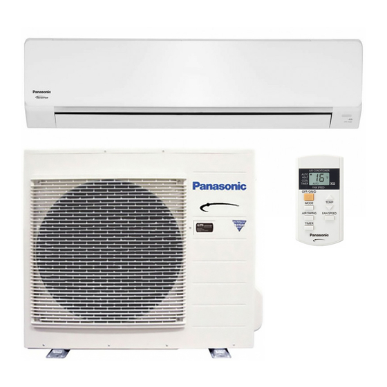
CS-YE18NKV-6
CS-YE24NKV-6
WARNING
PRECAUTION OF LOW TEMPERATURE
PAGE
6. Refrigeration Cycle Diagram...........................13
7. Block Diagram ..................................................14
8. Wiring Connection Diagram............................16
Indoor Unit
5.1 Indoor Unit & Remote Control ......................10
5.2 Outdoor Unit .................................................11
7.1 CS-YE18NKV-6 CU-YE18NKV-6.................14
7.2 CS-YE24NKV-6 CU-YE24NKV-6.................15
8.1 Indoor Unit....................................................16
© Panasonic Appliances Air-Conditioning Malaysia Sdn.
Bhd. 2012. Unauthorized copying and distribution is a
violation of law.
Order No: PHAAM1201029C3
Outdoor Unit
CU-YE18NKV-6
CU-YE24NKV-6
PAGE
Advertisement
Table of Contents
Troubleshooting

Related Manuals for Panasonic CS-YE18NKV-6


Summary of Contents for Panasonic CS-YE18NKV-6
-
Page 1: Table Of Contents
4.1 Indoor Unit............9 7.2 CS-YE24NKV-6 CU-YE24NKV-6....15 4.2 Outdoor Unit ...........9 4.3 Remote Control ..........9 8. Wiring Connection Diagram......16 5. Dimensions ............10 8.1 Indoor Unit............16 © Panasonic Appliances Air-Conditioning Malaysia Sdn. Bhd. 2012. Unauthorized copying and distribution is a violation of law. - Page 2 8.2 Outdoor Unit ..........17 9. Electronic Circuit Diagram ......19 9.1 Indoor Unit ............19 9.2 Outdoor Unit ..........20 10. Printed Circuit Board ........22 10.1 Indoor Unit ............22 10.2 Outdoor Unit ..........24 11. Installation Instruction........27 11.1 Select the Best Location.......27 11.2 Indoor Unit ............28 11.3 Outdoor Unit ..........32 12.
-
Page 3: Safety Precautions
1. Safety Precautions Read the following “SAFETY PRECAUTIONS” carefully before perform any servicing. Electrical work must be installed or serviced by a licensed electrician. Be sure to use the correct rating of the power plug and main circuit for the model installed. ... - Page 4 WARNING 20. During pump down operation, stop the compressor before remove the refrigeration piping. (Removal of refrigeration piping while compressor is operating and valves are opened condition will cause suck-in of air, abnormal high pressure in refrigeration cycle and result in explosion, injury etc.).
-
Page 5: Specifications
2. Specifications Indoor CS-YE18NKV-6 CS-YE24NKV-6 Model Outdoor CU-YE18NKV-6 CU-YE24NKV-6 Performance Test Condition Phase, Hz Single, 60 Single, 60 Power Supply Min. Mid. Max. Min. Mid. Max. 0.96 4.74 6.00 0.96 6.24 8.10 Capacity BTU/h 3300 16200 20400 3300 21200 27600 Running Current 10.3... - Page 6 Indoor CS-YE18NKV-6 CS-YE24NKV-6 Model Outdoor CU-YE18NKV-6 CU-YE24NKV-6 Type Propeller Fan Propeller Fan Material Motor Type PWM (8-poles) Induction (6-poles) Input Power Output Power Cool Speed Heat Moisture Removal L/h (Pt/h) 2.6 (5.5) 3.5 (7.4) Cool /min (ft /min) 13.63 (481) 13.14 (464)
- Page 7 Indoor CS-YE18NKV-6 CS-YE24NKV-6 Model Outdoor CU-YE18NKV-6 CU-YE24NKV-6 Dry Bulb Wet Bulb Dry Bulb Wet Bulb Maximum Cooling Indoor Minimum Operation Maximum Range Heating Minimum Maximum Cooling Outdoor Minimum Operation Maximum Range Heating Minimum Cooling capacities are based on indoor temperature of 27°C Dry Bulb (80.6°F Dry Bulb), 19.0°C Wet Bulb (66.2°F Wet Bulb) and outdoor air temperature of 35°C Dry Bulb (95°F Dry Bulb), 24°C Wet Bulb (75.2°F Wet Bulb)
-
Page 8: Features
3. Features Inverter Technology Wider output range Energy saving More precise temperature control Environment Protection Non-ozone depletion substances refrigerant (R410A) Long Installation Piping CS/CU-YE18NKV-6, CS/CU-YE24NKV-6, long piping up to 20 meter Easy to use remote control ... -
Page 9: Location Of Controls And Components
4. Location of Controls and Components Indoor Unit Outdoor Unit Remote Control... -
Page 10: Dimensions
5. Dimensions Indoor Unit & Remote Control... -
Page 11: Outdoor Unit
Outdoor Unit 5.2.1 CU-YE18NKV-6... - Page 12 5.2.2 CU-YE24NKV-6...
-
Page 13: Refrigeration Cycle Diagram
6. Refrigeration Cycle Diagram... -
Page 14: Block Diagram
7. Block Diagram CS-YE18NKV-6 CU-YE18NKV-6... -
Page 15: Cs-Ye24Nkv-6 Cu-Ye24Nkv-6
CS-YE24NKV-6 CU-YE24NKV-6... -
Page 16: Wiring Connection Diagram
8. Wiring Connection Diagram Indoor Unit... -
Page 17: Outdoor Unit
Outdoor Unit 8.2.1 CU-YE18NKV-6... - Page 18 8.2.2 CU-YE24NKV-6...
-
Page 19: Electronic Circuit Diagram
9. Electronic Circuit Diagram Indoor Unit... -
Page 20: Outdoor Unit
Outdoor Unit 9.2.1 CU-YE18NKV-6... - Page 21 9.2.2 CU-YE24NKV-6...
-
Page 22: Printed Circuit Board
10. Printed Circuit Board 10.1 Indoor Unit 10.1.1 Main Printed Circuit Board... - Page 23 10.1.2 Indicator Printed Circuit Board...
-
Page 24: Outdoor Unit
10.2 Outdoor Unit 10.2.1 Main Printed Circuit Board 10.2.1.1 CU-YE18NKV-6... - Page 25 10.2.1.2 CU-YE24NKV-6...
- Page 26 10.2.2 Noise Filter Printed Circuit Board 10.2.2.1 CU-YE24NKV-6...
-
Page 27: Installation Instruction
11. Installation Instruction 11.1 Select the Best Location 11.1.3 Indoor/Outdoor Unit Installation 11.1.1 Indoor Unit Diagram Do not install the unit in excessive oil fume area such as kitchen, workshop and etc. There should not be any heat source or steam near the unit. -
Page 28: Indoor Unit
11.2 Indoor Unit 11.2.1 How to Fix Installation Plate The mounting wall shall be strong and solid enough to prevent it from vibration. Dimension Model YE18***, YE24*** 585 mm 82 mm 165 mm 158 mm 169 mm 219 mm The center of installation plate should be at more than 1 at right and left of the wall. The distance from installation plate edge to ceiling should more than 2. - Page 29 11.2.3 Indoor Unit Installation 11.2.3.1 For the Right Rear Piping 11.2.3.2 For the Right and Right Bottom Piping 11.2.3.3 For the Embedded Piping (This can be used for left rear piping and bottom piping also.)
-
Page 30: Connect The Cable To The Indoor Unit
11.2.4 Connect the Cable to the Indoor Unit Install the indoor unit on the installing holder that mounted on the wall. Remove front grille by loosening the screw. Remove metal cover without damaging aluminium foil. Connection cable between indoor unit and outdoor unit shall be approved polychloroprene sheathed 4 x 1.5 mm (2.0 ~ 2.5HP) flexible cord, type designation 60245 IEC 57 or heavier cord. - Page 31 Remove the tapes and connect the power supply cord and connection cable between indoor unit and outdoor unit according to the diagram below. Secure the power supply cord and connection cable onto the control board with the holder. Fix back metal cover to original position without damaging aluminium foil. Ensure metal cover is fitted at both end.
-
Page 32: Outdoor Unit
11.3 Outdoor Unit 11.3.1 Install the Outdoor Unit After selecting the best location, start installation to Indoor/Outdoor Unit Installation Diagram. Fix the unit on concrete or rigid frame firmly and horizontally by bolt nut (ø10 mm). When installing at roof, please consider strong wind and earthquake. Please fasten the installation stand firmly with bolt or nails. -
Page 33: Evacuation Of The Equipment
11.3.3 Evacuation of the Equipment WHEN INSTALLING AN AIR CONDITIONER, BE SURE TO EVACUATE THE AIR INSIDE THE INDOOR UNIT AND PIPES in the following procedure. Connect a charging hose with a push pin to the Low side of a charging set and the service port of the 3-way valve. -
Page 34: Connect The Cable To The Outdoor Unit
11.3.4 Connect the Cable to the Outdoor Unit Remove the control board cover from the unit by loosening the screw. Cable connection to the power supply through Isolating Devices (Disconnecting means). Connect approved type polychloroprene sheathed power supply cord 3 x 2.5 mm² (2.0 ~ 2.5HP) type designation 60245 IEC 57 or heavier cord to the terminal board, and connect the others end of the cord to Isolating Devices (Disconnecting means). -
Page 35: Operation And Control
12. Operation and Control 12.1 Basic Function Inverter control, which equipped with a microcomputer in determining the most suitable operating mode as time passes, automatically adjusts output power for maximum comfort always. In order to achieve the suitable operating mode, the microcomputer maintains the set temperature by measuring the temperature of the environment and performing temperature shifting. -
Page 36: Automatic Operation
12.1.4 Automatic Operation This mode can be set using remote control and the operation is decided by remote control setting temperature, remote control operation mode, indoor intake air temperature and outdoor air temperature. During operation mode judgment, indoor fan motor (with speed of Lo-) and outdoor fan motor are running for 30 seconds to detect the indoor intake and outdoor air temperature. -
Page 37: Airflow Direction
[Heating] According to indoor pipe temperature, automatic heating fan speed is determined as follows. B. Feedback control Immediately after the fan motor started, feedback control is performed once every second. During fan motor on, if fan motor feedback ≥ 2550 rpm or < 50 rpm continue for 10 seconds, then fan motor error counter increase, fan motor is then stop and restart. - Page 38 Automatic vertical airflow direction can be set using remote control; the vane swings up and down within the angles as stated above. For heating mode operation, the angle of the vane depends on the indoor heat exchanger temperature as Figure 1 below. It does not swing during fan motor stop. When the air conditioner is stopped using remote control, the vane will shift to close position.
-
Page 39: Timer Control
12.3 Timer Control 12.3.1 To Set the Timer To turn ON the unit at a preset time, set the timer while the unit is OFF. To turn OFF the unit at a delayed time, set the timer while the unit is ON. ... -
Page 40: Protection Control
13. Protection Control 13.1 Protection Control for All Operations 13.1.1 Time Delay Safety Control The compressor will not start for three minutes after stop of operation. This control is not applicable if the power supply is cut off and on again or after 4-way valve deices condition. 13.1.2 Total Running Current Control When the outdoor unit total running current (AC) exceeds X value, the frequency instructed for compressor... - Page 41 13.1.4 Compressor Overheating Prevention Control Instructed frequency for compressor operation will be regulated by compressor top temperature. The changes of frequency are as below figure. If compressor discharge temperature exceeds 107°C (YE18NK) and 112°C (YE24NK), compressor will be stop, occurs 4 times per 20 minutes, timer LED will be blinking (“F97” is to be confirmed). 13.1.5 Low Pressure Prevention Control (Gas Leakage Detection) A.
-
Page 42: Protection Control For Cooling Operation
13.2 Protection Control for Cooling Operation 13.2.1 Outdoor Air Temperature Control The compressor operating frequency is regulated in accordance to the outdoor air temperature as shown in the diagram below. This control will begin 1 minute after the compressor starts. Compressor frequency will adjust base on Outdoor Air Temperature. -
Page 43: Protection Control For Heating Operation
13.2.6 Odor Cut Control To reduce the odor released from the unit. Start Condition AUTO FAN Speed is selected during COOL operation. During freeze prevention control and timer preliminary operation, this control is not applicable. Control content ... -
Page 44: Servicing Mode
14. Servicing Mode 14.1 Auto OFF/ON Button OPERATION MODE The operation will be activated immediately once the AUTO OFF/ON button is pressed. This operation can be used to operate air conditioner with limited function if remote control is misplaced or malfunctioned. TEST RUN OPERATION (FOR PUMP DOWN/SERVICING PURPOSE) The Test Run operation will be activated if the Auto OFF/ON button is pressed continuously for more than 5 seconds. -
Page 45: Troubleshooting Guide
15. Troubleshooting Guide 15.1 Refrigeration Cycle System In order to diagnose malfunctions, make sure that there are no electrical problems before inspecting the refrigeration cycle. Such problems include insufficient insulation, problem with the power source, malfunction of a compressor and a fan. -
Page 46: Relationship Between The Condition Of The Air Conditioner And Pressure And Electric Current
15.2 Relationship Between The Condition Of The Air Conditioner And Pressure And Electric Current Cooling Mode Heating Mode Condition of the Low Pressure High Pressure Electric current Low Pressure High Pressure Electric current air conditioner during operation during operation Insufficient refrigerant (gas leakage) Clogged capillary tube or Strainer... -
Page 47: Breakdown Self Diagnosis Function
15.3 Breakdown Self Diagnosis Function 15.3.1 Self Diagnosis Function (Three Digits Alphanumeric Code) Once error occurred during operation, the unit will stop its operation, and Timer LED blinks. Although Timer LED goes off when power supply is turned off, if the unit is operated under a breakdown condition, the LED will ON again. - Page 48 15.3.5 Temporary Operation (Depending On Breakdown Status) Press the Auto OFF/ON button on the main unit (a “beep” sound is heard) to operate the unit. (Remote control is enable again). The unit can be temporarily be used until repaired. Error Code Operation Temporary items Cooling...
-
Page 49: Error Code Table
15.4 Error Code Table Diagnosis Emergency Abnormality / Protection control Abnormality Judgment Primary location to verify display Operation No abnormality detected Normal operation Internal / external cable connection Indoor / Outdoor abnormal > 1 min after starting Indoor fan operation communication operation only... -
Page 50: Troubleshooting Flowchart
15.5 Troubleshooting Flowchart 15.5.1 H11 (Indoor/Outdoor Abnormal Communication) Malfunction Decision Conditions During startup and operation of cooling and heating, the data received from outdoor unit in indoor unit signal transmission is checked whether it is normal. Malfunction Caused Faulty indoor unit PCB. - Page 51 15.5.2 H12 (Indoor/Outdoor Capacity Rank Mismatched) Malfunction Decision Conditions During startup, error code appears when different types of indoor and outdoor units are interconnected. Malfunction Caused Wrong models interconnected. Wrong indoor unit or outdoor unit PCBs mounted. ...
- Page 52 15.5.3 H14 (Indoor Intake Air Temperature Sensor Abnormality) Malfunction Decision Conditions During startup and operation of cooling and heating, the temperatures detected by the indoor intake air temperature sensor are used to determine sensor errors. Malfunction Caused Faulty connector connection. ...
- Page 53 15.5.4 H15 (Compressor Temperature Sensor Abnormality) Malfunction Decision Conditions During startup and operation of cooling and heating, the temperatures detected by the outdoor compressor temperature sensor are used to determine sensor errors. Malfunction Caused Faulty connector connection. Faulty sensor.
- Page 54 15.5.5 H16 (Outdoor Current Transformer Open Circuit) Malfunction Decision Conditions A current transformer (CT) is detected by checking the compressor running frequency (≥ rated frequency) and CT detected input current (less than 1.14A) for continuously 20 seconds. Malfunction Caused ...
- Page 55 15.5.6 H19 (Indoor Fan Motor – DC Motor Mechanism Locked) Malfunction Decision Conditions The rotation speed detected by the Hall IC during fan motor operation is used to determine abnormal fan motor (feedback of rotation > 2550rpm or < 50rpm) Malfunction Caused ...
- Page 56 15.5.7 H23 (Indoor Pipe Temperature Sensor Abnormality) Malfunction Decision Conditions During startup and operation of cooling and heating, the temperatures detected by the indoor heat exchanger temperature sensor are used to determine sensor errors. Malfunction Caused Faulty connector connection. ...
- Page 57 15.5.8 H27 (Outdoor Air Temperature Sensor Abnormality) Malfunction Decision Conditions During startup and operation of cooling and heating, the temperatures detected by the outdoor air temperature sensor are used to determine sensor errors. Malfunction Caused Faulty connector connection. ...
- Page 58 15.5.9 H28 (Outdoor Pipe Temperature Sensor Abnormality) Malfunction Decision Conditions During startup and operation of cooling and heating, the temperatures detected by the outdoor pipe temperature sensor are used to determine sensor errors. Malfunction Caused Faulty connector connection. ...
- Page 59 15.5.10 H30 (Compressor Discharge Temperature Sensor Abnormality) Malfunction Decision Conditions During startup and operation of cooling and heating, the temperatures detected by the outdoor discharge pipe temperature sensor are used to determine sensor errors Malfunction Caused Faulty connector connection ...
- Page 60 15.5.11 H33 (Unspecified Voltage between Indoor and Outdoor) Malfunction Decision Conditions The supply power is detected for its requirement by the indoor/outdoor transmission. Malfunction Caused Wrong models interconnected. Wrong indoor unit and outdoor unit PCBs used. Indoor unit or outdoor unit PCB defective.
-
Page 61: Troubleshooting
15.5.12 H97 (Outdoor Fan Motor - DC Motor Mechanism Locked) Malfunction Decision Conditions The rotation speed detected by the Hall IC during fan motor operation is used to determine abnormal fan motor Malfunction Caused Operation stops due to short circuit inside the fan motor winding. ... - Page 62 15.5.13 H98 (Indoor High Pressure Protection) Error Code will not display (no Timer LED blinking) but store in EEPROM Malfunction Decision Conditions During heating operation, the temperature detected by the indoor pipe temperature sensor is above 60°C. Malfunction Caused ...
- Page 63 15.5.14 H99 (Indoor Freeze Prevention Protection: Cooling) Malfunction Decision Conditions Freeze prevention control takes place (when indoor pipe temperature is lower than 2°C) Malfunction Caused Clogged air filter of the indoor unit Dust accumulation on the indoor unit heat exchanger ...
- Page 64 15.5.15 F11 (Indoor Pipe Temperature Sensor Abnormality) Malfunction Decision Conditions When cooling operation, when indoor pipe temperature or indoor heat exchanger temperature sensor is above 45°C. Malfunction Caused Faulty connector connection. Faulty indoor pipe temperature sensor. Faulty indoor main PCB.
- Page 65 15.5.16 F90 (Power Factor Correction Protection) Malfunction Decision Conditions During startup and operation of cooling and heating, when Power Factor Correction (PFC) protection circuitry at the outdoor unit main PCB senses abnormal high DC voltage level. Malfunction Caused DC voltage peak due to power supply surge.
- Page 66 15.5.17 F91 (Refrigeration Cycle Abnormality) Malfunction Decision Conditions During cooling, compressor frequency = Fcmax. During cooling and heating operation, running current: 0.65A < I < 1.65A. During cooling, indoor intake - indoor pipe < 4°C. Malfunction Caused ...
- Page 67 15.5.18 F93 (Compressor Rotation Failure) Malfunction Decision Conditions A compressor rotation failure is detected by checking the compressor running condition through the position detection circuit. Malfunction Caused Compressor terminal disconnect Outdoor PCB malfunction Troubleshooting...
- Page 68 15.5.19 F95 (Cooling High Pressure Abnormality) Malfunction Decision Conditions During operation of cooling, when outdoor unit heat exchanger high temperature data (61°C) is detected by the outdoor pipe temperature sensor. Malfunction Caused Outdoor pipe temperature rise due to short circuit of hot discharge air flow. ...
- Page 69 15.5.20 F96 (IPM Overheating) Malfunction Decision Conditions During operating of cooling and heating, when IPM temperature data (100°C) is detected by the IPM temperature sensor. Malfunction Caused IPM overheats due to short circuit of hot discharge air flow. IPM overheats due to defective of outdoor fan motor.
- Page 70 15.5.21 F97 (Compressor Overheating) Malfunction Decision Conditions During operation of cooling and heating, when compressor tank temperature data (112°C) is detected by the compressor tank temperature sensor. Malfunction Caused Refrigerant shortage (refrigerant leakage). 2/3 way valve closed. Detection error due to faulty compressor tank temperature sensor.
- Page 71 15.5.22 F98 (Input Over Current Detection) Malfunction Decision Conditions During cooling and heating operation, when an input over-current (X value in Total Running Current Control) is detected by checking the input current value being detected by current transformer (CT) with the compressor running. Malfunction Caused ...
- Page 72 15.5.23 F99 (Output Over Current Detection) Malfunction Decision Conditions During operation of cooling and heating, when an output over-current (18.5A) is detected by checking the current that flows in the inverter DC peak sensing circuitry. Malfunction Caused DC peak due to compressor failure. ...
-
Page 73: Disassembly And Assembly Instructions
16. Disassembly and Assembly Instructions WARNING High Voltage is generated in the electrical parts area by the capacitor. Ensure that the capacitor has discharged sufficiently before proceeding with repair work. Failure to heed this caution may result in electric shocks. 16.1 Small Air Filter, Indoor Electronic Controllers and Control Board Removal Procedures... -
Page 76: To Remove Cross Flow Fan And Indoor Fan Motor
16.2 To Remove Cross Flow Fan and Indoor Fan Motor... -
Page 78: Technical Data
17. Technical Data 17.1 Operation Characteristics 17.1.1 CS-YE18NKV-6 CU-YE18NKV-6 Cooling Characteristic at Different Outdoor Air Temperature Condition Room temperature: 26.7°C (DBT), 19.4°C (WBT) Operation condition: High fan speed Piping length: 7.5m Compressor frequency: F... - Page 79 Cooling Characteristic at Different Piping Length Condition Room temperature: 26.7°C (DBT), 19.4°C (WBT) Operation condition: High fan speed Outdoor temperature: 35°C (DBT), 24°C (WBT) Compressor frequency: F...
- Page 80 Heating Characteristic at Different Outdoor Air Temperature Condition Room temperature: 21.1°C (DBT) Operation condition: High fan speed Piping length: 7.5m Compressor frequency: F...
- Page 81 Heating Characteristic at Different Piping Length Condition Room temperature: 21.1°C (DBT) Operation condition: High fan speed Outdoor temperature: 8.3°C (DBT), 6.1°C (WBT) Compressor frequency: F...
- Page 82 17.1.2 CS-YE24NKV-6 CU-YE24NKV-6 Cooling Characteristic at Different Outdoor Air Temperature Condition Room temperature: 26.7°C (DBT), 19.4°C (WBT) Operation condition: High fan speed Piping length: 7.5m Compressor frequency: F...
- Page 83 Cooling Characteristic at Different Piping Length Condition Room temperature: 26.7°C (DBT), 19.4°C (WBT) Operation condition: High fan speed Outdoor temperature: 35°C (DBT), 24°C (WBT) Compressor frequency: F...
- Page 84 Heating Characteristic at Different Outdoor Air Temperature Condition Room temperature: 21.1°C (DBT) Operation condition: High fan speed Piping length: 7.5m Compressor frequency: F...
- Page 85 Heating Characteristic at Different Piping Length Condition Room temperature: 21.1°C (DBT) Operation condition: High fan speed Outdoor temperature: 8.3°C (DBT), 6.1°C (WBT) Compressor frequency: F...
-
Page 86: Exploded View And Replacement Parts List
18. Exploded View and Replacement Parts List 18.1 Indoor Unit Note The above exploded view is for the purpose of parts disassembly and replacement. The non-numbered parts are not kept as standard service parts. - Page 87 REF. NO. PART NAME & DESCRIPTION CS-YE18NKV-6 CS-YE24NKV-6 REMARK CHASSIS COMPLETE CWD50C1654 ← FAN MOTOR ARW7627AC ← CROSS-FLOW FAN COMPLETE CWH02C1077 ← SCREW - CROSS-FLOW FAN CWH551146 ← BEARING ASSY CWH64K007 ← EVAPORATOR CWB30C2900 CWB30C2777 FLARE NUT (LIQUID) CWT251030 ←...
- Page 88 REF. NO. PART NAME & DESCRIPTION CS-YE18NKV-6 CS-YE24NKV-6 REMARK SHOCK ABSORBER ( L ) CWG713273 ← SHOCK ABSORBER ( R ) CWG713274 ← C.C.CASE CWG567993 CWG567994 (Note) All parts are supplied from PAPAMY, Malaysia (Vendor Code: 00029488). “O” marked parts are recommended to be kept in stock.
-
Page 89: Outdoor Unit
18.2 Outdoor Unit 18.2.1 CU-YE18NKV-6 Note The above exploded view is for the purpose of parts disassembly and replacement. The non-numbered parts are not kept as standard service parts. - Page 90 REF. NO. PART NAME & DESCRIPTION CU-YE18NKV-6 REMARK CHASSIS COMPLETE CWD52K1261 ANTI - VIBRATION BUSHING CWH50077 COMPRESSOR 5RD132XBA21 NUT - COMPRESSOR MOUNT CWH56000J SOUND PROOF MATERIAL CWG302632 FAN MOTOR BRACKET CWD541153 FAN MOTOR ARW8401AC SCREW - FAN MOTOR BRACKET CWH551217 SCREW - FAN MOTOR MOUNT CWH551106J PROPELLER FAN ASSY...
- Page 91 REF. NO. PART NAME & DESCRIPTION CU-YE18NKV-6 REMARK SHOCK ABSORBER (LEFT) CWG713217 SHOCK ABSORBER (RIGHT) CWG713218 C.C.CASE CWG567955 (Note) All parts are supplied from PAPAMY, Malaysia (Vendor Code: 00029488). “O” marked parts are recommended to be kept in stock.
- Page 92 18.2.2 CU-YE24NKV-6 Note The above exploded view is for the purpose of parts disassembly and replacement. The non-numbered parts are not kept as standard service parts.
- Page 93 REF. NO. PART NAME & DESCRIPTION CU-YE24NKV-6 REMARK CHASSIS COMPLETE CWD52K1190 ANTI - VIBRATION BUSHING CWH50055 PACKING CWB81043 COMPRESSOR 5KD240XAF21 NUT - COMPRESSOR MOUNT CWH561049 FAN MOTOR BRACKET CWD541126 FAN MOTOR CWA951712 SCREW - FAN MOTOR BRACKET CWH551217 SCREW - FAN MOTOR MOUNT CWH551040J PROPELLER FAN ASSY CWH001019...
- Page 94 REF. NO. PART NAME & DESCRIPTION CU-YE24NKV-6 REMARK SHOCK ABSORBER (RIGHT) CWG712879 SHOCK ABSORBER (LEFT) CWG712880 C.C.CASE CWG567956 (Note) All parts are supplied from PAPAMY, Malaysia (Vendor Code: 00029488). “O” marked parts are recommended to be kept in stock. Printed in Malaysia YB0112-0...
Need help?
Do you have a question about the CS-YE18NKV-6 and is the answer not in the manual?
Questions and answers