Table of Contents
Advertisement
This service information is designed for experienced repair technicians only and is not designed for use by the general public.
It does not contain warnings or cautions to advise non-technical individuals of potential dangers in attempting to service a product.
Products powered by electricity should be serviced or repaired only by experienced professional technicians. Any attempt to
service or repair the products dealt with in this service information by anyone else could result in serious injury or death.
TABLE OF CONTENTS
1. Safety Precautions.............................................3
2. Specification .......................................................5
2.1
CS/CU-YC9MKV, CS/CU-YC12MKV...........5
2.2
2.3
CS/CU-YC12MKV-6 .....................................9
3. Location of Controls and Components .........11
3.1
Indoor Unit..................................................11
3.2
Outdoor Unit ...............................................11
3.3
Remote Control ..........................................11
4. Dimensions .......................................................12
4.1
Indoor Unit..................................................12
4.2
Outdoor Unit ...............................................13
5. Refrigeration Cycle Diagram...........................14
Indoor Unit
CS-YC9MKV
CS-YC12MKV
CS-YC12MKV-6
CS-YC9MKV-7
CS-YC12MKV-7
WARNING
6. Block Diagram ..................................................15
7. Wiring Connection Diagram............................16
7.1
Indoor unit ..................................................16
7.2
Outdoor Unit ...............................................17
8. Installation Instruction.....................................18
8.1
Select The Best Location ...........................18
8.2
Indoor Unit..................................................19
8.3
Outdoor Unit ...............................................22
9. Operation Control.............................................24
9.1
Cooling Operation ......................................24
9.2
Soft Dry Operation......................................25
9.3
Automatic operation ...................................25
9.4
Indoor Fan Speed Control..........................26
9.5
Outdoor Fan Speed Control .......................27
9.6
Vertical Airflow Direction Control................27
© Panasonic Home Appliances Air-Conditioning
(Guangzhou) Co.,Ltd (PHAAG) 2010. All rights
reserved. Unauthorized copying and distribution is a
violation of law.
Order No: PHA-AG1101002C3
Outdoor Unit
CU-YC9MKV
CU-YC12MKV
CU-YC12MKV-6
CU-YC9MKV-7
CU-YC12MKV-7
Advertisement
Table of Contents

Related Manuals for Panasonic CS-YC12MKV


Summary of Contents for Panasonic CS-YC12MKV
-
Page 1: Table Of Contents
Outdoor Unit ..........13 Indoor Fan Speed Control......26 Outdoor Fan Speed Control .......27 5. Refrigeration Cycle Diagram......14 Vertical Airflow Direction Control....27 © Panasonic Home Appliances Air-Conditioning (Guangzhou) Co.,Ltd (PHAAG) 2010. All rights reserved. Unauthorized copying and distribution is a violation of law. - Page 2 Horizontal Airflow Direction Control....27 Timer Control..........27 Random Auto Restart Control ....27 10. Protection Control..........28 10.1 Restart Control (Time Delay Safety Control) 10.2 7 minutes Time Save Control .....28 10.3 60 seconds Forced Operation ....28 10.4 30 Seconds Forced Operation ....28 10.5 Anti-Freezing Control .........28 10.6...
-
Page 3: Safety Precautions
1. Safety Precautions • Read the following “SAFETY PRECAUTIONS” carefully before perform any servicing. • Electrical work must be installed or serviced by a licensed electrician. Be sure to use the correct rating of the power plug and main circuit for the model installed. •... - Page 4 17. Recommended installation height for indoor unit shall be at least 2.5 m. 18. The appliance shall be installed in accordance with national wiring regulations. 19. Keep away from small children, the thin film may cling to nose and mouth and prevent breathing. 20.
-
Page 5: Specification
2. Specification CS/CU-YC9MKV, CS/CU-YC12MKV Indoor CS-YC9MKV CS-YC12MKV Model Outdoor CU-YC9MKV CU-YC12MKV Phase, Hz Single, 60 Single, 60 Power Supply 2.64 3.52 Capacity BTU/h 9000 12000 kJ/h 2270 3027 Running Current 4.30 5.50 Input Power 1180 2.93 2.98 Btu/hW 10.00 10.17... - Page 6 Weight Net (I/D / O/D) kg (lb) 8.0 (18) 21 (46) 8.0 (18) 26 (57) Pipe Diameter (Liquid / mm (inch) 6.35 (1/4) / 9.52 (3/8) 6.35 (1/4) / 12.70 (1/2) Gas) Standard length m (ft) 5.0 (16.4) 5.0 (16.4) Length range (min –...
-
Page 7: Cs/Cu-Yc9Mkv-7, Cs/Cu-Yc12Mkv-7
CS/CU-YC9MKV-7, CS/CU-YC12MKV-7 Indoor CS-YC9MKV-7 CS-YC12MKV-7 Model Outdoor CU-YC9MKV-7 CU-YC12MKV-7 Phase, Hz Single, 60 Single, 60 Power Supply 2.64 3.52 Capacity BTU/h 9000 12000 kJ/h 2270 3027 Running Current 4.30 5.50 Input Power 1180 2.93 2.98 Btu/hW 10.00 10.17 Power Factor... - Page 8 Weight Net (I/D / O/D) kg (lb) 8.0 (18) 21 (46) 8.0 (18) 26 (57) Pipe Diameter (Liquid / mm (inch) 6.35 (1/4) / 9.52 (3/8) 6.35 (1/4) / 12.70 (1/2) Gas) Standard length m (ft) 5.0 (16.4) 5.0 (16.4) Length range (min –...
-
Page 9: Cs/Cu-Yc12Mkv-6
CS/CU-YC12MKV-6 Indoor CS-YC12MKV-6 Model Outdoor CU-YC12MKV-6 Phase, Hz Single, 60 Power Supply 3.52 Capacity BTU/h 12000 kJ/h 3027 Running Current 5.50 Input Power 1180 2.98 Btu/hW 10.17 Power Factor Indoor Noise (H / L / QLo) dB-A 39 / 33 / - Outdoor Noise (H / L) dB-A 49 / -... - Page 10 Height(I/D / O/D) mm (inch) 283 (11-5/32) 530 (20-7/8) Dimension Width (I/D / O/D) mm (inch) 803 (31-5/8) 650 (25-19/32) Depth (I/D / O/D) mm (inch) 214 (8-7/16) 230 (9-1/16) Weight Net (I/D / O/D) kg (lb) 8.0 (18) 26 (57) Pipe Diameter (Liquid / Gas) mm (inch) 6.35 (1/4) / 12.70 (1/2)
-
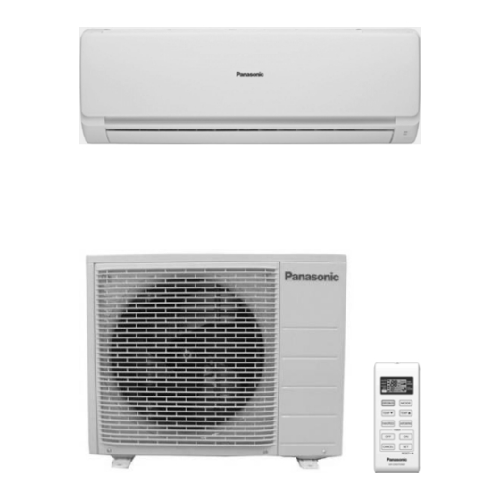
Page 11: Location Of Controls And Components
3. Location of Controls and Components Indoor Unit Outdoor Unit Remote Control... -
Page 12: Dimensions
4. Dimensions Indoor Unit Unit : mm... -
Page 13: Outdoor Unit
Outdoor Unit... -
Page 14: Refrigeration Cycle Diagram
5. Refrigeration Cycle Diagram Evaporator Condenser... -
Page 15: Block Diagram
6. Block Diagram POWER SUPPLY AC 220v, 60 Hz, SINGLE PHASE,... -
Page 16: Wiring Connection Diagram
7. Wiring Connection Diagram Indoor unit... -
Page 17: Outdoor Unit
Outdoor Unit... -
Page 18: Installation Instruction
8. Installation Instruction Select The Best Location 8.1.3 Indoor/Outdoor Unit 8.1.1 Indoor Unit • There should not be any heat source or steam near the unit. • There should not be any obstacles blocking the air circulation. • A place where air circulation in the room is good. •... -
Page 19: Indoor Unit
Indoor Unit 8.2.1 How to Fix Installation Plate The mounting wall is strong and solid enough to prevent if from the vibration. The centre of installation plate should be at more than 450 mm at right and left of the wall. The distance from installation plate edge to ceiling should more than 120 mm. - Page 20 8.2.3 Indoor Unit Installation...
-
Page 21: Connect The Cable To The Indoor Unit
8.2.4 Connect the Cable to the Indoor Unit The inside and outside connecting cable can be connected without removing the front grille. Connecting cable between indoor unit and outdoor unit shall be approved polychloroprene sheathed 3x 1.0 .( YC9MKV,YC9MKV-7) or 3 x 1.5mm (YC12MKV, YC12MKV-6, YC12MKV-7) flexible cords, type designation 245 IEC 57 or heavier cord. -
Page 22: Outdoor Unit
Outdoor Unit 8.3.1 Install the Outdoor Unit • After selecting the best location, start installation according to indoor/outdoor unit installation diagram. Fix the unit on concrete or rigid frame firmly and horizontally by bolt nut (ø10 mm). When installing at roof, please consider strong wind and earthquake. Please fasten the installation stand firmly with bolt or nails. -
Page 23: Connect The Cable To The Outdoor Unit
Connect a charging hose with a push pin to the Low side of a charging set and the service port of the 3-way valve. Be sure to connect the end of the charging hose with the push pin to the service port. Connect the center hose of the charging set to a vacuum pump. -
Page 24: Operation Control
9. Operation Control Cooling Operation Cooling Operation can be set using remote control. This operation is applied to cool down the room temperature to the setting temperature set on the remote control. The remote control setting temperature, which takes the reading of intake air temperature sensor, can be adjusted from 16℃... -
Page 25: Soft Dry Operation
Soft Dry Operation Soft Dry Operation can be set using remote control. Soft Dry operation is applied to dehumidify and to perform a gentle cooling to the room. When selecting Soft Dry operation, the operation will be cooling until the room temperature reaches the set temperature on remote control, and then soft Dry will be activated. -
Page 26: Indoor Fan Speed Control
Indoor Fan Speed Control Indoor fan speed can be set using remote control. 9.4.1 Fan Speed rotation Chart speed Model CS-YC9 1080 CS-YC12 1140 1000 9.4.2 Automatic Fan Speed Control When set to Auto Fan Speed, the fan speed is adjusted between maximum and minimum setting as shown in the table. -
Page 27: Outdoor Fan Speed Control
9.4.3 Manual Fan Speed Control Manual fan speed can be set with Fan Speed selection button at the remote control There are 3 level of fan speed setting : Lo, Me, Hi Outdoor Fan Speed Control There is only one speed for outdoor fan motor. When compressor stops, outdoor fan will continue running for 30 seconds. -
Page 28: Protection Control
Protection Control 10.1 Restart Control (Time Delay Safety Control) • When the thermo-off temperature is reach during Cooling operation, the compressor stops for 3 minutes (minimum) before resume operation. • When the thermo-off temperature is reach during Soft Dry operation, the compressor stops for 6 minutes (minimum) before resume operation. -
Page 29: Dew Prevention Control
10.7 Dew Prevention Control To prevent dew formation at indoor unit discharge area, the horizontal air vane is automatically set at position 2 (refer to 9.6). This control is activated when:- *Compressor runs continuously for 60 minutes. *Horizontal air vane is at position 4 or 5 (refer to 9.6). *Actual fan speed is lower than Lo level. -
Page 30: Servicing Mode
11. Servicing Mode 11.1 Auto Off/On Button 5 sec 10 sec 15 sec Auto Operation Test Run Operation Remote Control Random Auto Restart (Forced Cooling Operation) Receiving Sound OFF/ON OFF/ON Beep Beep x 2 Beep x 3 AUTO OPERATION MODE Auto Operation will be activated immediately once the Auto OFF/ON button is pressed. -
Page 31: Troubleshooting Guide
12. Troubleshooting Guide 12.1 Refrigeration Cycle System In order to diagnose malfunctions, ensure the air conditioner is free Normal Pressure and Outlet Air Temperature (Standard) Gas Pressure Outlet air from electrical problems before inspecting the refrigeration cycle. Temperature Such problems include insufficient insulation, problem with the (kg/cm (°C) power source, malfunction of a compressor and a fan. -
Page 32: Diagnosis Methods Of A Malfunction Of A Compressor
12.1.1 Relationship between the condition of the air conditioner and pressure and electric current Cooling Mode Condition of the air conditioner Low Pressure High Pressure Electric current during operation Insufficient refrigerant (gas leakage) Clogged capillary tube or strainer Short circuit in the indoor unit Heat radiation deficiency of the outdoor unit Inefficient compression... -
Page 33: Disassembly And Assembly Instructions
13. Disassembly and Assembly Instructions WARNING High Voltage is generated in the electrical parts area by the capacitor. Ensure that the capacitor has discharged sufficiently before proceeding with repair work. Failure to heed this caution may result in electric shocks. Removal Procedure for front panel 1. - Page 34 2.Remove the air filters and then pull out the front grille form the unit body. Front grille Removal Procedure for Discharge Grille 1. Separate the drain hose and the drain plate. 2. Pull out the discharge grille slightly.
- Page 35 Removal Procedure for Cross Flow Fan 1. Release fixing screws on both side, disassembly the fixing board from evaporator on the left side and pull out the whole evaporator. Fixing Screw 2. Loose the fixing screw of the cross flow fan. 3.
-
Page 36: Exploded View And Replacement Pars List
14. Exploded View and Replacement Pars List 14.1 Indoor Unit Note The above exploded view is for the purpose of parts disassembly and replacement. The non-numbered parts are not kept as standard service parts. - Page 37 REF. PART NAME & DESCRIPTION QTY. CS-YC9MKV CS-YC9MKV-6 CS-YC9MKV-7 Remark CHASSIS COMPLETE CWD50C1686 CWD50C1686 CWD50C1686 FAN MOTOR CWA921487 CWA921487 CWA921487 CROSS FLOW FAN COMPLETE CWH02C1101 CWH02C1101 CWH02C1101 BEARING ASSY CWH64K1007 CWH64K1007 CWH64K1007 EVAPORATOR CWB30C3374 CWB30C3374 CWB30C3374 AUXILIARY TUBE ASS'Y CWT01C5351...
- Page 38 REF. PART NAME & DESCRIPTION QTY. CS-YC12MKV CS-YC12MKV-6 CS-YC12MKV-7 Remark CHASSIS COMPLETE CWD50C1686 CWD50C1686 CWD50C1686 FAN MOTOR CWA921489 CWA921489 CWA921489 CROSS FLOW FAN COMPLETE CWH02C1101 CWH02C1101 CWH02C1101 BEARING ASSY CWH64K1007 CWH64K1007 CWH64K1007 EVAPORATOR CWB30C3432 CWB30C3432 CWB30C3432 AUXILIARY TUBE ASS'Y CWT01C5327 CWT01C5327 CWT01C5327 DRAIN PLUG...
-
Page 39: Outdoor Unit
14.2 Outdoor Unit Note The above exploded view is for the purpose of parts disassembly and replacement. The non-numbered parts are not kept as standard service parts. - Page 40 REF. PART NAME & DESCRIPTION QTY. CU-YC9MKV CU-YC9MKV-6 CU-YC9MKV-7 Remark CHASSIS ASS'Y CWD52K1216A CWD52K1216A CWD52K1216A FAN MOTOR BRACKET CWD541094 CWD541094 CWD541094 SCREW-FAN MOTOR BRACKET CWH551148A CWH551148A CWH551148A FAN MOTOR CWA951779 CWA951427 CWA951779 SCREW-FAN MOTOR MOUNT CWH55406J CWH55406J CWH55406J PROPELLER FAN ASS'Y CWH03K1025 CWH03K1025 CWH03K1025...
- Page 41 REF. PART NAME & DESCRIPTION QTY. CU-YC12MKV CU-YC12MKV-6 CU-YC12MKV-7 Remark CHASSIS ASS'Y CWD52K1216A CWD52K1216A CWD52K1216A FAN MOTOR BRACKET CWD541097 CWD541097 CWD541097 SCREW-FAN MOTOR BRACKET CWH551148A CWH551148A CWH551148A FAN MOTOR CWA951777 CWA951777 CWA951777 SCREW-FAN MOTOR MOUNT CWH55406J CWH55406J CWH55406J PROPELLER FAN ASS'Y CWH03K1025 CWH03K1025 CWH03K1025...
Need help?
Do you have a question about the CS-YC12MKV and is the answer not in the manual?
Questions and answers