Table of Contents
Advertisement
Advertisement
Table of Contents

Subscribe to Our Youtube Channel
Related Manuals for Hydro-Force Nautilus MX3-1200


Summary of Contents for Hydro-Force Nautilus MX3-1200
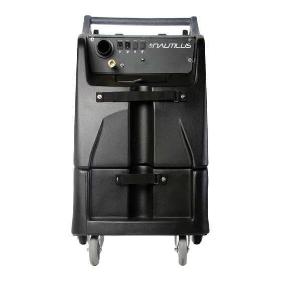
- Page 1 Nautilus MX3-1200 Operating Manual #LMANN02 Revised: 06-04-2014...
-
Page 2: Table Of Contents
Nautilus MX3-1200 Operating Manual TABLE OF CONTENTS TOPIC PAGE # • Introduction • Technical Specifications • Optional Equipment SECTION 1: Operational Safety • Electrical Safety • Mechanical Safety SECTION 2: Operation Procedures • Vacuum Connections • Electrical Supply • Water Supply & Chemicals •... -
Page 3: Introduction
Years of experience, engineering, and planning have gone into the design and manufacturing of the MX3-1200. We take a great deal of pride in the MX3-1200; our goal is no less than your complete satisfaction. -
Page 4: Technical Specifications
Technical Specifications MX3-1200 High Pressure Extractor Height: 42-1/4” Length: 34-3/8” Width: 23-3/8” Weight: 160 lbs. Solution Tank Capacity: 12 gallon Recovery Tank Capacity: 12 gallon Solution Pump: Pump-Tec #356 pump with 1-1/2 HP Motor 0-1200 psi – 2.2 gpm Vacuum Motors: Two AMETEK Lamb 5.7”... -
Page 5: Optional Equipment
Additional / Optional Equipment Carpet Wand: AW29 Wand Glide – Delrin for AW29 Wand AW529D Wand Glide – Teflon for AW29 Wand AW529T 18” Bottom Velcro Strap for Wand Holder NM5841 Foam Downer: AH17 Hose Hook: AH95 SX-15 Hard Surface Tool: AW105 Gekko Handle Assembly: AR51A... -
Page 6: Electrical Safety
(see Page 9 for details.) • Do not use the MX3-1200 outdoors, in standing water or on wet surfaces. Do not store the MX3-1200 in wet conditions. If extractor is leaking, unplug machine power cords from outlets before approaching or touching machine. -
Page 7: Mechanical Safety
Store, transport, and use this equipment only in temperatures well above freezing. (32ºF or 0ºC). If you suspect the MX3-1200 has been frozen, do not plug in or turn on machine until you are sure it has thawed completely. -
Page 8: Vacuum Connections
Section Vacuum Connections The MX3-1200 has a unique vacuum system which allows you to connect your vacuums in either parallel or in series. Vacuum connections can be changed quickly, with only a screw driver. While there is debate on which vacuum alignment provides the best extraction, this much is true: •... -
Page 9: Electrical Supply
SET UP AND OPERATION 1. Electrical Cords: Two 50’ power cords are supplied with the Nautilus MX3-1200. Cord #1 powers both vacuum motors and the cooling fan; Cord #2 powers the high pressure solution pump and the waste pump. The amperage required by each cord requires that the two cords be plugged into two separate 20amp circuits: •... -
Page 10: Water Supply & Chemicals
16-1/4oz of chemical to each gallon of water.) • The standard tip for use with the MX3-1200 is the turquoise tip with a dilution rate of 256:1. This means that for each gallon of water flowing into the machine, 1/2 ounce of chemical will be added. - Page 11 How to Change the Metering Tip: • Remove the chemical feed hose from the barb on the side of the proportioning valve. • Unscrew and remove the old tip. • Screw in the proper tip for your chemical tip and place the hose back on the barb Proportioning Valve Turquoise Tip Dilution 256 - 1...
- Page 12 Water Supply: • Once the correct metering tip is in place: o Connect the Auto-Fill Water Supply Hose to the water inlet (the male quick-connect on the front of the machine.) o Connect the other end of the hose to a water faucet, and then turn on the water. •...
-
Page 13: Solution Hose & Pump Priming
3. Connection of Solution Hose: Connect the high pressure solution hose to the solution outlet (female quick connect on the front of the machine). Connect the other end of the hose to the male quick connect on the cleaning tool. When you are ready to start cleaning, turn the solution pump switch to the ON position HP Solution Hose Assembly –... -
Page 14: Vacuum Hoses
The vacuum connection on the machine can be either a 2” hose barb or 2” male Flash Cuff. Both are included with your MX3-1200. The desired connector can be threaded into the vacuum port on the front of the machine. -
Page 15: Foam Downer
The Foam Downer kills foam as waste water enters the machine. Place a container of liquid defoamer on the top of your MX3-1200. The vacuum air flow siphons the liquid defoamer through Foam Downer into the vacuum tank, breaking down the foam before it can cause any damage or make a mess. -
Page 16: Pump-Out System
6. Connection of Pump-out Hose: The pump-out hose is a 50’ section of 3/4” garden hose. (Use of smaller diameter hose may reduce flow.) • Remove the cap from the pump-out outlet fitting on the back of the machine. • Connect the pump-out hose to the outlet fitting. •... -
Page 17: Pressure Adjustments
7. Pressure Adjustment: To make it easier to check and adjust the pressure, the pressure gauge and the pressure regulator/unloader are mounted on the control panel on the front of the machine. When the high-pressure solution pump is on and primed, pressure will show on the gauge only while the tool is being sprayed. -
Page 18: Shutdown Procedures
Shutdown Procedures: • If using the auto-fill system, turn the water supply off before finishing each job. This will allow use of the water and chemical already in the tank, and will reduce the amount of excess water to be disposed of later. •... -
Page 19: Accessory Storage
Bucket & Sprayer Storage The top of the MX3-1200 is sized and recessed to hold a five gallon bucket or two one-gallon chemical bottles as well as two 2QT sprayers. Power Cord Storage The back of the MX3-1200 has two sets of cord wraps to hold two 12/3 x 50’... -
Page 20: Troubleshooting
Section Troubleshooting Troubleshooting – Nautilus MX3-1200 Problem Cause Solution Machine not Building circuit breaker tripped. Reset breakers or move cords to other outlets turning on - Faulty power cord Replace cord (AX33) No power Faulty switches or internal wiring Check wiring & test switches - Repair as needed *... - Page 21 Problem Cause Solution Dual Circuit Cords on the same circuit Move one cord to outlet on different circuit Indicator No voltage from one/ both outlets Check circuit breakers – Reset breakers or move cords Not Lighted Light Bad Replace Light Dual Circuit Indicator Bad Replace indicator If hot &...
- Page 22 Problem Cause Solution Tool won't Jets clogged Clean out or replace jets spray - low or Inline filter clogged Clean out or replace filter uneven spray Jets worn Replace jets Jets not aligned properly Re-align jets Tool valve faulty Repair or replace valve Quick connects or hoses restricted Clean out or replace quick connects and/or hoses Solution Tank...
-
Page 23: Solution Flow Path
MX3-1200 Solution Flow Path Inlet Quick Float Valve Connect Solution Tank Outlet Quick Connect Filter Chemical Jug Pump – AP48 Pressure Regulator / Unloader – PT017 Priming Valve When Priming Valve held open water flows through hose to Recovery Tank... -
Page 24: Wiring Diagrams
M1200 MX3-1200 Wiring Diagram Wiring Diagram – Cord #1 PUMP OUT SOL PUMP VAC 2 VAC 1 CIRCUIT BREAKER 20AMP 12GA COOLING FAN CORD #1 12/3 Dual Circuit Indicator SOLUTION VAC2 VAC1 PUMP Machine Base... - Page 25 MX3-1200 Wiring Diagram – Cord #2 PUMP OUT SOL PUMP VAC 2 VAC 1 CIRCUIT BREAKER 20AMP 12GA CORD #2 12/3 Dual Circuit Indicator PUMP OUT SOLUTION PUMP GREEN Machine Base...
- Page 26 NAUTILUS MX3-1200 SWITCH PANEL: Solution Pump Switch – Power from Cord #2. Vacuum #1 – Power from Cord #1. When the switch is turned to the ON position When the switch is turned to the ON power is supplied to the solution pump motor.
-
Page 27: Maintenance
Section Maintenance Proper maintenance is required to keep the MX3-1200 operating properly, prevent downtime and to extend the life of your equipment. WARNING: Disconnect electrical power before performing any service or maintenance inside machine base or before testing or repairing switches or power cords. - Page 28 Inside the recovery tank, on top of the stand pipe, is the Vacuum Shutoff Assembly. It functions to prevent debris and water from being sucked into the vacuum motors. Operating the MX3-1200 without the Vacuum Shutoff Assembly or with a poorly maintained assembly will greatly decrease the life of the vacuum motors and will void the warranty.
- Page 29 This debris can clog the Waste Pump and the Vacuum Shutoff Assembly. The Hydro-Filter II must be examined and cleaned regularly to keep the MX3-1200 functioning properly: • Grasp and turn the lid counterclockwise to open the Hydro-Filter II lid.
- Page 30 CLEAN WASTE PUMP-OUT PUMP: Build-up of fine silt inside the Waste Pump can clog the pump even if the pump is not used, so this maintenance procedure should be performed regardless of whether the Waste Pump has been used. • After cleaning out the recovery tank, remove the cap and connect the Pump-Out hose to the Waste Pump outlet fitting on the back of the machine;...
- Page 31 A restricted Pump Inlet Filter can prevent the solution pump from providing adequate pressure for cleaning. A restriction or air leak on the pump inlet hose can also damage the solution pump check valves and plunger Inside View: MX3-1200 Solution Tank seals. CAUTION: Before proceeding with this procedure, make sure both power cords are disconnected.
- Page 32 FLUSH CHEMICAL SYSTEM: Chemical build-up in the chemical system can prevent the system from drawing chemical. • Rinse the chemical system with fresh water (For heavy chemical build-up, a mild acid can be added to the rinse water.) • Remove the chemical feed hose from the solution tank and place the end of the hose in a bucket of fresh water or mild acid solution.
- Page 33 LUBRICATE PRESSURE REGULATOR O-RINGS: To maintain consistent adequate pressure delivery to the cleaning tool, the o-rings on the stem of the MX3- 1200 pressure regulator must be lubricated regularly. 1. Remove the black knob from the regulator. 2. Unscrew the brass knob assembly from the piston retainer. 3.
- Page 34 CLEAN RECOVERY TANK DRAIN Debris and sand accumulation in the drain valve can damage the valve or prevent it from closing completely. This will result in dirty water leaking from the valve. Use of the Hydro-Filter and regular cleaning of the recovery tank will help prevent this, but occasionally the drain valve will require cleaning or replacement.
- Page 35 This will assure that the anti-freeze will be drawn into the proportioning valve. 4. Connect any cleaning tools that will be stored with the MX3-1200. Direct tool spray back into the solution tank or into a bucket. Repeat for all tools to be protected.
- Page 36 Section Parts Replacement parts available for repair of your MX3-1200. MX3-1200 PUMP – AP48 PARTS ASSEMBLY KIT C – PT046 KIT A – PT042 KIT B – PT044...
-
Page 37: Pump
PUMPTEC #356 PUMP – AP48 ITEM DESCRIPTION PART NUMBER PLUNGER 0311-0006-0002 PLUNGER GUIDE 0311-0009 O-RING FOR PLUNGER GUIDE C0100-1124 U-CUP C0220-1075 U-CUP BACKING RING 0311-0011 PUMP HEAD 0356-0002-0001 PUMP MANIFOLD 0356-0004-0001 VALVE ASSEMBLY 0205-0012 VALVE SEAT (Part of #8 - Valve Assembly) 0205-0017 VALVE POPPET (Part of #8 - Valve Assembly) 0205-0013... -
Page 38: Auto-Fill
– M013 AUTO-FILL ASSEMBLY NM5751 BR282A AH102B BR282A NM5751 BR286 NM5740 Float Valve Assembly See Parts Breakdown on Next Page BR286 BR138... - Page 39 NM5740 AUTO-FILL FLOAT VALVE ASSEMBLY...
-
Page 40: Pressure Unloader
PT017 HP UNLOADER ITEM DESCRIPTION ITEM DESCRIPTION ITEM DESCRIPTION HP UNLOADER PT017 PISTON O-RING - LARGE SEAT O-RING BLACK PLASTIC KNOB PISTON RETAINER SEAT PT017KNOB BRASS KNOB PISTON RETAINER O-RING BRASS BODY LOCKING NUT PISTON O-RING - SMALL POPPET O-RING SPRING PISTON WASHER - SMALL POPPET... -
Page 41: Pump-Out Pump
Pump-Out Pump AP37 PARTS ASSEMBLY... - Page 43 19 & 19A CONTROL PANEL REAR VIEW - BASE & BASE SKIRT 55 & 56 55 & 56 41 & 41A HINGE SCREWS...
- Page 44 REAR VIEW – BASE, BASE SKIRT & RECOVERY TANK 14 & 14a 36 & 79 27 & 27A VACUUM PLUG ASSEMBLY...
- Page 45 55 & 56 55 & 56 3, 58 & 59 3, 58 & 59 TOP VIEW OF BASE...
- Page 46 VACUUM MOUNTS & CONNECTIONS 9, 54 & 64 9, 54 & 64 9, 54 & 64...
- Page 47 3 & 59 61 & 62 63 & 55 61 & 62 3 & 59 BOTTOM VIEW OF BASE 9 & 54 9 & 54 PUMP & PRIMING VALVE...
- Page 48 80 & 55 36 & 36A 9 & 41 BOTTOM VIEW SOLUTION TANK & BASE SKIRT...
- Page 49 BOTTOM VIEW SOLUTION TANK 9, 30 & 31 INSIDE SOLUTION TANK...
- Page 50 INSIDE RECOVERY TANK VACUUM SHUTOFF AND PUMP-OUT FILTER REMOVED INSIDE RECOVERY TANK WITH PUMP-OUT FILTER IN PLACE VACUUM SHUTOFF ASSEMBLY...
- Page 51 PUMP-OUT CONNECTIONS 97 & 9...
- Page 52 PUMP-OUT PARTS FLOW...
-
Page 53: Parts List
ACORN NUT CAP 5/16-18 NM5743 CONTROL PANEL PLATE NM5137 SCREW 5/16-18 X 2.75” HX SS NM5743B MX3-1200 PANEL DECAL NM5718 LID ASSY WASTE TANK NM5009 CORD 12GA W/ PLUG (QTY 2) SCREW #10 X 5/8” PH SS(QTY 6) CORD STRAIN RELIEF (QTY 2) - Page 54 KEY PART # DESCRIPTION PART # DESCRIPTION PHY094-034 NUT 10-24 NYLOCK SS(QTY 4) BARB ½” X 3/8” MPT BR030 AXLE REAR WHEELS – 22.5” HOSE ½” ID CLEAR COIL NM5748 NM5086 1200PSI PUMP WITH MOTOR ELBOW 90 BARB ½” X 3/8” MPT AP48 PRIMING VALVE ELBOW 90 BARB 3/8”...
- Page 55 BR282A NM5701 BARB ¾” X ¾” FPT KIT DUAL CIRCUIT WIRING BR049 NM5758 PHY106-028 RUBBER VACUUM PLUG DECAL NAUTILUS SIDE NM5711 (QTY 2) SCREW TEK #10 X 5/8” SS SCREW 1/4-20 X .63” SOC BH SS NM4263 NM4087 CABLE #6 INTERNAL STAR WASHER SS...
-
Page 56: Hose List
DESCRIPTION HOSE TYPE LENGTH NOTES VAC HOSE 2” VAC – NM5726 29” TANK END: REC TANK TO MANIFOLD SOLD PER FT 1 - NM5713 2 – NM5025 VAC END: HOSE CLAMP PA051 VAC HOSE 2” VAC – NM5726 9.5” VAC END: VAC 1 TO MANIFOLD SOLD PER FT HOSE CLAMP... -
Page 57: Limited Warranty
Section Limited Warranty Your Nautilus MX3-1200 is designed to give you years of reliable service. If a problem should arise use the troubleshooting section in the operation manual to diagnose and correct the problem if possible. If you are unable to determine the cause or solution to the problem contact your distributor or Hydro-Force for assistance.
Need help?
Do you have a question about the Nautilus MX3-1200 and is the answer not in the manual?
Questions and answers