Table of Contents
Advertisement
Advertisement
Table of Contents

Related Manuals for Onwa KP-6299C


Summary of Contents for Onwa KP-6299C
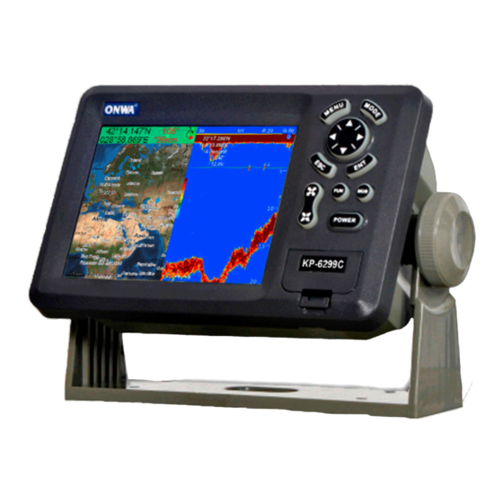
- Page 1 KP-6299C/8299C/1299C OPERATOR'S MANUAL MARINE GPS PLOTTER...
-
Page 3: Table Of Contents
CONTENTS FOREWORD OPERATION OVERVIEW 1.1 Keypad instruction Turning ON and OFF Power Adjusting Brilliance and DIM Display Modes PLOTTER DISPLAY OVERVIEW Choosing the Display Range Shifting the Cursor Shifting the Display Centering Own Ship's Position Coordinates Map data Heading Line Range Circle Palette 2.10... - Page 4 WAYPOINT/MOB Entering Waypoints Entering the MOB Mark Displaying Waypoint Name Operation on the Waypoint Editing Erasing Waypoints 5 ROUTES Creating Routes Editing Routes Erasing Routes DESTINATION Setting Destination by Cursor Setting Destination by Waypoint Setting Route as Destination Setting Track Data as Destination Canceling Destination 6.6 Distance ALARM...
- Page 5 DRAWING Drawing Marks Drawing Lines 8.3 Drawing Place name 8.4 Editing Drawing Marks Editing Drawing Lines Editing Drawing Place Name Erasing Drawing Marks 8.8 Erasing Drawing Lines 8.9 Erasing Drawing Place Name 9 OTHER SETTING 9.1 Map Scale 9.2 Unit of Measurement 9.3 Bearing Reference 9.4 Magnetic Variation 9.5 Deviation...
- Page 6 11.5 Physical 11.6 Equipment List 12 INSTALLATION 12.1 Verifying the contents 12.2 Installing the unit 12.3 KP-6299C Table of connecting 12.4 KP-8299C Table of connecting 12.5 KP-1299C Table of connecting 12.6 KP-6299C Display unit size 12.7 KP-8299C Display unit size...
-
Page 7: Foreword
FOREWORD The KP-6299C/8299C/1299C ONWA GPS PLOTTER aid are specially designed for the vessel traffic management, ONWA is a professional brand of the domestic and foreign navigation products. The products are designed to be all-sealed and waterproof, can be rapid position-fixing and resistant to poor environment. The software is powerful by using the advanced ARM9 processors can be capable to display faster, and the design for operation is professional and reasonable, can be easy to use. -
Page 8: Operation Overview
1. OPERATION OVERVIEW 1.1 Keypad instruction (Figure 1-1) Plotter function The key is used to move the cursor or to change the setting. Sounder function turnning the VRM on Plotter function moving the cursor/chart to the right Sounder function To select feeding rate of the screen. Sounder function Phasing the Basic range selected(setting upper range limit). -
Page 9: Turning On And Off Power
1.2 Turning ON and OFF Power Turning on the power Press the [ON/OFF] key. The unit beeps and display ONWA " " logo. After a few seconds starts up with the last-used display mode. Turning off the power Press and hold down the [ON/OFF] key unit the screen goes blank (about four seconds). -
Page 10: Display Modes
1.4 Display Modes Your unit has seven display modes: PLOTTER SCREEN, NAVIGATOR SCREEN, POSITION SCREEN, SATELLITE SCREEN, AIS SCREEN, SOUNDER SCREEN and PLOTTER + SOUNDER SCREEN. Press the [MODE] key to choose a display mode. Each time the key is pressed, the display mode changes in the sequence shown below. -
Page 11: Plotter Display Overview
2. PLOTTER DISPLAY OVERVIEW 2.1 Choosing the Display Range You may press to choose display range on plotter and highway displays. 2.2 Shifting the Cursor Use the cursor pad to shift the cursor. The cursor moves in the direction of the arrow or diagonal pressed on the cursor pad. -
Page 12: Shifting The Display
2.3 Shifting the Display The display can be shifted on the plotter display. Operate the cursor pad to place the cursor at an edge of the screen. The display shifts in the direction opposite to cursor pad operation. 2.4 Centering Own Ship's Position Press the [ESC] key for centering own Ship's position. -
Page 13: Map Data
2.6 Map data 1. Press [MENU] key in PLOTTER screen. 2. Choose MAP and then press [ ] key. 3. Choose the layer ON or OFF as appropriate and then press [ENT] key to " " " " finish. (K-Chart) (C-MAP) 2.7 Heading Line 1. -
Page 14: Range Circle
2.8 Range Circle 1. Press [MENU] key in PLOTTER screen. 2. Choose RANGE CIRCLE and then press [ENT] key. 3. Choose ON (if choose ON you need input the circle radius manually) or " " " " " OFF as appropriate and then press [ENT] key to finish. "... -
Page 15: Map Orientation
2.10 Map Orientation 1. Press [MENU] key in PLOTTER screen. 2. Choose MAP DIRECTION and then press [ENT] key. 3. Choose Normal , NORTH Upward , WPT Upward or BOW Upward " " " " " " " " as appropriate and then press [ENT] key to finish. 2.11 Perspective View 1. - Page 16 3. Choose the layer ON as appropriate and then press [ENT] key to finish. 4. Choose the layer OFF as appropriate and then press [ENT] key to finish.
-
Page 17: Track
3. TRACK 3.1 Changing Track Plotting Interval, Stopping Plotting When the track memory becomes full, the oldest track is erased to make room for the latest. 1. Press the [MENU] key twice to main menu. 2. Choose TRACK RECORD and then press [ ] key. 3. -
Page 18: Displaying The Track
3.2 Displaying the Track 1. Press [MENU] key in PLOTTER screen. 2. Choose TRACK and then press [ ] key. 3. Choose the color and Choose turn it ON or OFF. 4. Press [MENU] key to finish. 3.3 Creating Track Data 1. -
Page 19: Erasing Track
3.4 Erasing Track 1. Press [MENU] twice to main menu. 2. Choose [ERASE] and then press [ ] key. 3. For saved track then press [ ] key to choose Current track or Saved track. 4. Choose the color that you want to erase or choose ALL if you want to erase all. and then Press [ENT] key. -
Page 20: Waypoint/Mob
4. WAYPOINT/MOB 4.1 Entering Waypoints Waypoints can be entered on the plotter display three ways: at cursor position, at own ship's position, and from the waypoint edit. Entering a waypoint with the cursor 1. Use the cursor pad to place the cursor on the location desired for a waypoint. 2. - Page 21 Entering a waypoint from the waypoint list 1. Press the [MENU] key twice to main menu. 2. Choose EDIT and then press [ ] key. 3. Choose WAYPOINT and then press [ENT] key. The following window will appear 4. Choose NEW then press [ENT] key. The following window appears.
-
Page 22: Entering The Mob Mark
4.2 Entering the MOB Mark Only one MOB mark may be entered. Each time the MOB mark is entered the previous MOB mark and its position data are written over. 1. Long Press the [MOB] key on any display unit. The following display appears. -
Page 23: Operation On The Waypoint Editing
4.4 Operation on the Waypoint Editing Waypoint position, waypoint name, mark shape, mark color and comment can be edited from the Waypoint Edit. 1. Press the [MENU] key twice to main menu. 2. Choose EDIT and then press [ ] key. 3. -
Page 24: Erasing Waypoints
4.5 Erasing Waypoints 1. Press the [MENU] key twice to main menu. 2. Choose EDIT and then press [ ] key. 3. Choose WAYPOINT and then press the [ENT] key. 4. Select a WPT and press [ENT] key. 5. The confirm window will appear, choose ERASE and then press [ENT] 6. -
Page 25: Routes
5. ROUTES 5.1 Creating Routes 1. Press [MENU] key twice to main menu. 2. Choose EDIT and then press [ ] key. 3. Choose ROUTE and then press [ENT] key. The following window will appear. 4. Choose NEW and then press [ENT] key. "... - Page 26 5. Use enter the route name and then press [ENT] key. The following will appear. 6. Choose location (e.g. 01) and then press [ENT] key. Will open a new window let you choose waypoint. 7. Choose the waypoint name and then press [ENT] key. (In example, 001) You can also create a new waypoint if needed.
-
Page 27: Editing Routes
5.2 Editing Routes Replacing waypoints in a route 1. Press the [MENU] key twice to main menu. 2. Choose EDIT and then press [ ] key. 3. Choose ROUTE and then press [ENT] key. 4. Choose the route to edit and then press [ENT] key. 5. -
Page 28: Erasing Routes
Permanently deleting a waypoint from a route 1. Press the [MENU] key twice to main menu. 2. Choose EDIT and then press the [ ] Key. 3. Choose ROUTE and then press [ENT] key. 4. Choose the route desired and then press [ENT] key. 5. - Page 29 4. Select a Route then press [ENT]. 5. The confirm window will appear, choose ERASE and then press [ENT] key. 6. Choose YES and then press [ENT] to finish. Erase All Routes 1. Press the [MENU] key twice to main menu. 2.
-
Page 30: Destination
6. DESTINATION 6.1 Setting Destination by Cursor 1. Press [F] key. 2. Choose [GOTO CURSOR] and then press [ENT] key. " " 3. The cursor appears with ? . 4. Use the cursor pad to place the cursor on the location desired for destination. 5. -
Page 31: Setting Destination By Waypoint
6.2 Setting Destination by Waypoint 1. Press the [F] key. 2. Choose GOTO WPT and then press [ENT] key. 3. The SELECT GOTO WPT list appears. 4. Choose a Waypoint and then press [ENT] key. 6.3 Setting Route as Destination 1. - Page 32 3. The SELECT GOTO ROUTE list appears. 4. Choose a route and then press [ENT] key. The following window appears. 5. Choose Forward or Reverese in order in which to traverse the route waypoints, and then press [ENT] key. Intermediate Point 2 [ROUTE 01] (WPT SW) (WPT B)
-
Page 33: Setting Track Data As Destination
6.4 Setting Track Data as Destination Track Data can use for navigation. 1. Press the [F] key to display the GOTO options window. " " 2. Choose GOTO TRACK . 3. Press the [ENT] key. 4. Choose Track Log to display the following menu. 5. -
Page 34: Canceling Destination
Once a GOTO TRACK has been activated, the track will divides it into " " segments. Up to 200 temporary waypoint are created (named T1,T2, T3, etc. and END) to mark the most significant features of the track, duplicating your exact path as closely as possible. To get the most out of the GOTO TRACK feature, remember the following tips: Always clear the track log at the point that you want to go back to. -
Page 35: Distance
6.6 Distance Measure distance of several points and save it as a route 1. 1.Press [F] key in plotter screen to display Function menu " " 2. Select Distance and press [ENT] to activate the distance measurement function. 000.0 M 22 20.310N 0.00 115 21.310E... - Page 36 5. Move the cursor to next point (C). Now the BRG and LEG display the Bearing and Distance from B to point C, DIST remain display the total distance from point A to point B. 151.6 M 22 20.310N 17.04 115 21.310E 9.97 Press [ENT], now DIST = distance of point AB + distance of point BC (27.01nm)
-
Page 37: Alarm
7. ALARM There are SIX alarm conditions which generate both audio and visual alarms: Arrival alarm, Anchor drag alarm, XTE (Cross-Track Error) alarm, Speed alarm, Buzzer alarm, Voltage alarm and Time alarm. When the alarm setting is violated, the buzzer sounds and the name of offending alarm and the alarm icon appear on the display. -
Page 38: Arrival Alarm
3. Choose ANCHOR and then press [ENT] key. The alarm options appear. 4. Choose item 3 and then press [ENT] to setup the alarm value. 5. Choose ON and then press [ENT] key to enable the alarm. 7.2 Arrival Alarm 1. -
Page 39: Xte (Cross-Track Error) Alarm
7.3 XTE (Cross-Track Error) Alarm 1. Press [MENU] key twice to main menu. 2. Choose ALARM and then press [ ] key to display alarm menu. 3. Choose XTE and then press [ENT] key. The alarm options appear. 4. Choose item 3 and then press [ENT] to setup alarm value. 5. -
Page 40: Voltage Alarm
7.5 Voltage Alarm 1. Press [MENU] key to main menu. 2. Choose ALARM and then press [ ] key to display alarm menu. 3. Choose VOLTAGE and then press [ENT] key. The alarm options appear. 4. Choose item 3 and then press [ENT] to setup alarm value. 5. -
Page 41: Buzzer Type Selection
7.7 Buzzer Type Selection The buzzer sounds whenever an alarm setting is violated. 1. Press the [MENU] twice to main menu. 2. Choose ALARM and then press [ ] key. 3. Choose BUZZER and then press [ ] key. 4. Choose buzzer type desired and then Press [ENT] key. SHORT: Two short beeps LONG: Three long beeps CONSTANT: Continuous beeps... -
Page 42: Drawing
8. DRAWING 8.1 Drawing Marks 1. Press [F] key. 2. Choose [DRAWING] and then press [ ] key. 3. Choose [MARK] and then press [ENT] key . " " o The cursor appears with n the PLOTTER SCREEN. 4. Use the cursor pad place the cursor on the location desired add a mark and then press [ENT] key. -
Page 43: Drawing Lines
8.2 Drawing Lines 1. Press [F] key. 2. Choose [DRAWING] and then press [ ] key. 3. Choose [LINE] and then press [ENT]. The cursor appears with "+?" On the PLOTTER SCREEN. 4. The cursor appear with a ? . "... -
Page 44: Editing Drawing Marks
8.4 Editing Drawing Marks 1. Press [MENU] key twice to main menu. 2. Choose EDIT and then press [ ] key. 3. Choose Drawing marks and then press [ENT] key. The following window appears. 4. Select a mark for edit then press [ENT]. 5. -
Page 45: Editing Drawing Lines
8.5 Editing Drawing Lines 1. Press [MENU] key twice to main menu. 2. Choose EDIT and then press [ ] key. 3. Choose DRAWING LINES and then press [ENT] key. The following window appears. 4. Choose the line that you want to edit and then press [ENT] key. The following window appears. -
Page 46: Editing Drawing Place Name
8.6 Editing Drawing Place Name 1. Press [MENU] key twice to main menu. 2. Choose EDIT and then press [ ] key. 3. Choose DRAWING PALCENAME and then press [ENT] key. The following window appears. 5. Choose the place name that you want to edit and then press [ENT] key. The following window appears. -
Page 47: Erasing Drawing Marks
8.7 Erasing Drawing Marks 1. Press [MENU] key twice to main menu. 2. Choose EDIT and then press [ ] Key. 3. Choose DRAWING MARKS and the press [ENT] Key. 4. Choose the mark that you want to clear, and then press [ENT] key. The confirmation window will appears. -
Page 48: Erasing Drawing Lines
8.8 Erasing Drawing Lines 1. Press [MENU] key twice to main menu. 2. Choose EDIT and then press [ ] key. 3. Choose DRAWING LINES and the press [ENT] Key. 4. Choose the line that you want to erase, and then press [ENT] key. The confirmation window appears. -
Page 49: Erasing Drawing Place Name
8.9 Erasing Drawing Place Name 1. Press [MENU] key twice to main menu. 2. Choose EDIT and then press [ ] key. 3. Choose DRAWING PALCENAME and then press [ENT] key. 4. Choose the place name that you want to erase, and then press [ENT] key. The confirmation window appears. -
Page 50: Other Setting
9. OTHER SETTING 9.1 Map Scale You can change the map scale display format. 1. Press [MENU] key twice to main menu. 2. Choose SETUP and then press [ ] key. 3. Choose MAP SCALE and then press [ENT] key. 4. -
Page 51: Bearing Reference
5. Choose DEPTH Unit and then press [ENT] key. 6. Choose Feet(ft) , Fathom(fa) or Meter(m) as appropriate and then press " " " " " " [ENT] key to finish. 9.3 Bearing Reference Ship's course and bearing to a waypoint may be displayed in true or magnetic bearing. -
Page 52: Magnetic Variation
9.4 Magnetic Variation The location of the magnetic north pole is different from the geographical North Pole.This causes a difference between the true and magnetic north direction. This difference is called magnetic variation, and varies with respect to the observation point on earth. Your unit is preprogrammed with all the earth's magnetic variation. -
Page 53: Deviation
9.5 Deviation You can input the deviation of ship or map manually to correct the position error from GPS error or map error. 1. Press [MENU] key twice to main menu. 2. Choose SETUP and then press [ ] key. 3. -
Page 54: Ttg/Eta Speed
9.7 TTG/ETA speed To calculate time-to-go and estimated time of arrival, enter your speed as below. 1. Press the [MENU] key twice to main menu. 2. Choose SETUP and then press[ ] key. 3. Choose TTG/ETA SPEED and thenpress [ENT] key. 4. - Page 55 9.8.2 Datum setting You can choose 6 types data output at the same time. 1. Press [MENU] on the SATELATE SCREEN. 2. Choose DATUM and press [ENT] key. 3. Choose your desired datum and press [ENT] to confirm. 9.8.3 Smoothing You can setup position smoothing, speed smoothing and course smoothing.
- Page 56 9.9 NMEA data display 1. Press [MENU] key twice to main menu. 2. Choose SETUP and then press [ ] key. 3. Choose NMEA data display and then press [ENT] key. 4. NMEA data display is used during the installation to check whether the NMEA input and output data to and from other equipment onboard is normal.
-
Page 57: Echo Sounder Overview
10. ECHO SOUNDER OVERVIEW 10. ECHO SOUNDER OVERVIEW 10.1 Sonar mode 1. Press [MENU] key in SOUNDER screen. 2. Choose SONAR MODE and then press [ENT] key or press and hold [MODE] key in SOUNDER screen, the following window will appear. MODE Function 200K... - Page 58 200K, 50K (high frequency, low frequency) mode The sounder uses ultrasonic pulses to detect bottom conditions. The lower the frequency of the pulse the wider the detection area. Therefore, the 50KHz frequency is useful for general detection and judging bottom conditions, while the 200KHz frequency is useful for detailed observation of fish schools.
-
Page 59: Gain
10.2 Gain 1. Press [MENU] key in SOUNDER screen. 2. Choose Gain and then press [ENT] key, the following window will appear. or press [ENT] key in SOUNDER screen, GAIN window will appear. 3. Choose Manual, Fishing or Cruising as appropriate and then press the [ENT] key. or press and hold [ENT] key in SOUNDER screen, Active in the ground fish model of automatic gain. -
Page 60: Tvg
10.4 TVG 1. Press [MENU] key in SOUNDER screen. 2. Choose TVG and then press [ENT] key, the following window will appear. The TVG compensates for propagation loss of sound, so that the echoes from the same size fish schools are displayed in the same color. Normally, set it between 0 and 5 . -
Page 61: Pic. Advance
10.5 Pic. advance The picture advance speed determines how quickly the vertical scan lines run across the screen. 1. Press [MENU] key in SOUNDER screen. 2. Choose Pic. advance and then press [ENT] key or press and hold [ ] key in SOUNDER screen.the following window will appear. -
Page 62: Sonar Menu
10.7 SONAR MENU 1. Press [MENU] key in SOUNDER screen. 2. Choose Sonar menu and then press [ENT] key, the following window will appear. 10.7.1 A-Scope 1. Press [MENU] key in SOUNDER screen. 2. Choose Sonar menu and then press [ENT] key. 3. -
Page 63: Zoom Mode
10.7.2 Zoom mode 1. Press [MENU] key in SOUNDER screen. 2. Choose Sonar menu and then press [ENT] key. 3. Choose Zoom mode and then press [ENT] key, the following window will appear. MARKER ZOOM This mode expands selected area of the normal picture to full vertical size of the screen on the left-half window. -
Page 64: Bottom Lock
BOTTOM LOCK This display provides a compressed normal picture on the top 2/3 of the screen and a 5 or 10 meter (10 or 20 feet) wide layer in contact with the bottom is expanded onto the bottom 1/3 of the screen. This mode is useful for bottom discrimination. Note that the seabed should be steadily and distinctly plotted in red or reddish-brown. - Page 65 10.7.3 Noise limiter Light-blue dots may appear over most of screen. This is mainly due to unclean water or noise.This noise can be suppressed by adjusting CLUTTER on the menu. 1. Press [MENU] key in SOUNDER screen. 2. Choose Sonar menu and then press [ENT] key. 3.
- Page 66 10.7.5 Signal level 1. Press [MENU] key in SOUNDER screen. 2. Choose Sonar menu and then press [ENT] key. 3. Choose Signal level and then press [ENT] key, the following window will appear. 4. Press the [ ] or [ ] key to select to apply the signal level and press [ENT] to finish.
-
Page 67: Alarm
10.8 ALARM 1. Press [MENU] key in SOUNDER screen. 2. Choose ALARM and then press [ENT] key, the following window will appear. 3. Press [ ] or [ ] to select an alarm 4. Press [ENT] to select ON, IN or OUT.(For the water temperature alarm, select IN to get the alarm when the water temperature is within the alarm zone range, or OUT to get the alarm when the water temperature is higher than the alarm zone range.) 5. -
Page 68: System Menu
10.9 SYSTEM MENU 1. Press [MENU] key in SOUNDER screen. 2. Choose SYSTEM MENU and then press [ENT] key, the following window will appear. RANGE 1- 10: Activates or deactivates specific range scales. Default ranges are 5, 10, 20, 40, 80, 150, 200, 300, 600, and 1000 (meters). Setting area is 2 m to 800 m. -
Page 69: Data Field
10.10 Data field 1. Press [MENU] key in SOUNDER screen. 2. Choose Data field and then press [ENT] key, the following window will appear. 3. Data field setup The right of the screen will appear the Data Field. The black area is the data area of which may be changed. - Page 70 Short cuts in Plotter screen 1) Press and hold [Mode] to change the track color. 2) Press and hold [ESC] to turn track record on and off. 3) Press and hold [ENT] to activate the User Mark drawing function. Short cuts in Fishfinder (Sounder) screen 1) Press and hold [Mode] to change the fishfinder mode, 50K, 200K, 50/200K, 50Z and 200Z.
-
Page 71: Main Performance And Specifications
NOAA paper chart colors Tides: Tide data Projection: Mercator projection Position format: Lat/Lon Basemap: Built-in Onwa K-Chart External Map: SD Cards slot for C-Map MAX User data storage: Internal backup of user settings, or e xternal SD-card Plot Interval: 1s to 99h or 0.01nm to 9.99nm Plotting scales: 0.01nm... -
Page 72: Power Supply
Outputs for autopilot: $--AAM, $--APB, $--BOD, $--VTG PERSPECTIVE VIEW: On/off 11.2 POWER SUPPLY 1) KP-6299C: 10.5 to 35VDC, current drain<2A at 12V 2) KP-8299C/1299C: 10.5 to 35VDC, current drain<2.5A at 12V 11.3 GPS RECEIVER CHARACTERISTICS Receiver: 50 parallel channel GPS receiver continuously Tracks and... -
Page 73: Ais Interface
106mm(D) Weight: KP-6299C: 0.9kg KP-8299C: 2.43kg KP-1299C: 3.95kg KP-6299C: 5.6-inches Color TFT day-view LCD 640 480 pixels Display: KP-8299C: 8-inches Color TFT day-view LCD 800 600 pixels KP-1299C: 12.1-inches Color TFT day-view LCD 800 600 pixels Waterproofing: Display unit: IPX5... - Page 74 8 colors (including background color) according to echo intensity. The background color is selectable from blue, light blue, white and black. Basic Range Meters 10/20/40/80/150/300/500/1000 (for KP-6299C, up to 600m) Feet 30/60/120/250/500/1000/1600/3000 (for KP-6299C, up to 1500ft) Fathoms 5/10/20/40/80/160/250/500 (for KP-6299C, up to 200fa)
-
Page 75: Installation
12. INSTALLATION 12. INSTALLATION 12.1 Verifying the contents When opening the box,please verify that all items in the following drawing are present. ONWA Control/Display Unit Mounting Bracket GPS Antenna Transducer Operation Manual Spare Fuses 2A fuse should be used for power voltage 12v. -
Page 76: Installing The Unit
12.2 Installing the unit Notice: The unit should be mounted on a flat, solid surface for maximum stability. Be sure to fix the mounting bracket with screws. Otherwise, the display unit may fall down by the boat s pitching and rolling to the lead to the fire or the injury. (1) The mounting bracket should be fixed with 6mm screws. -
Page 77: Kp-6299C Table Of Connecting
12.3 KP-6299C Table of connecting DATA INPUT/OUTPUT NMEA 0183IN + NMEA 0183IN NMEA 0183IN 2+ 2OUT RS-232OUT Temp Antenna Antenna ONWA OPTION FUSE Power Supply Receptacle Dc input(-) Dc input(+), 11 to 40V... -
Page 78: Kp-8299C Table Of Connecting
12.4 KP-8299C Table of connecting DATA INPUT/OUTPUT NMEA 0183IN + NMEA 0183IN NMEA 0183IN 2+ 2OUT RS-232OUT Temp Antenna Antenna ONWA OPTION FUSE Power Supply Receptacle Dc input(-) Dc input(+), 11 to 40V... -
Page 79: Kp-1299C Table Of Connecting
12.5 KP-1299C Table of connecting DATA INPUT/OUTPUT NMEA 0183IN + NMEA 0183IN NMEA 0183IN 2+ 2OUT RS-232OUT Temp Antenna Antenna ONWA FUSE OPTION Power Supply Receptacle Dc input(-) Dc input(+), 11 to 40V... -
Page 80: Kp-6299C Display Unit Size
12.6 KP-6299C Display unit size 199.1 224.1 201.2... -
Page 81: Kp-8299C Display Unit Size
12.7 KP-8299C Display unit size 289.8 261.5 99.5 29.5 289.8... -
Page 82: Kp-1299C Display Unit Size
12.8 KP-1299C Display unit size 363.8 30.5 65.3 363.8...
Need help?
Do you have a question about the KP-6299C and is the answer not in the manual?
Questions and answers