Sharp VL-NZ50U Service Manual

Liquid crystal digital camcorder
Hide thumbs Also See for VL-NZ50U:

Advertisement

1. IMPORTANT SERVICE NOTES ........................................................................................................ 2
2. SPECIFICATIONS .............................................................................................................................. 6
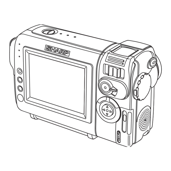
3. PART NAMES .................................................................................................................................... 7
4. DISASSEMBLY OF THE SET ............................................................................................................ 8
5. MECHANISM ADJUSTMENT JIGS AND PARTS ............................................................................ 10
ITEMS AND INTERVALS ................................................................................................................. 11
7. MECHANICAL ADJUSTMENTS AND CHECKS .............................................................................. 12
8. TAPE RUNNING ADJUSTMENT ..................................................................................................... 15
(DISASSEMBLY AND REASSENBLY) ........................................................................................... 17
10.ADJUSTING THE ELECTRICAL CIRCUITS .................................................................................... 24
11.USEFUL TIPS ................................................................................................................................... 42
12.SIGNAL FLOW DIAGRAMS ............................................................................................................. 43
13.BLOCK DIAGRAMS ......................................................................................................................... 46
14.SCHEMATIC DIAGRAMS ................................................................................................................ 52
15.SEMICONDUCTOR LEAD IDENTIFICATION ............................................................................... 116
16.PRINTED WIRING BOARD ASSEMBLIES .................................................................................... 118
17.REPLACEMENT PARTS LIST ....................................................................................................... 135
18.PACKING OF THE SET ................................................................................................................. 155
SHARP CORPORATION
SERVICE MANUAL
LIQUID CRYSTAL DIGITAL CAMCORDER
MODELS
In the interests of user-safety (Required by safety regula-
tions in some countries) the set should be restored to its
original condition and only parts identical to those specified
be used.
CONTENTS
This document has been published to be used for
after sales service only.
The contents are subject to change without notice.
1
VL-NZ50U/NZ100U
VL-NZ150U
S22F9VL-NZ50U
VL-NZ50U
VL-NZ100U
VL-NZ150U
Page
NTSC

Advertisement

Table of Contents
loading

Summary of Contents for Sharp VL-NZ50U

  • Page 1: Table Of Contents

    VL-NZ50U/NZ100U VL-NZ150U SERVICE MANUAL S22F9VL-NZ50U LIQUID CRYSTAL DIGITAL CAMCORDER NTSC VL-NZ50U VL-NZ100U VL-NZ150U MODELS In the interests of user-safety (Required by safety regula- tions in some countries) the set should be restored to its original condition and only parts identical to those specified be used.
  • Page 2: Important Service Notes

    VL-NZ50U/NZ100U VL-NZ150U 1. IMPORTANT SERVICE NOTES connections, metal cabinet, screw heads, knobs and BEFORE RETURNING THE VIDEO CAMERA control shafts, etc.) and measure the AC voltage drop RECORDER across the resistor. Reverse the AC plug (a non polarized adaptor plug must be used but only for the...
  • Page 3 VL-NZ50U/NZ100U VL-NZ150U WARNING :TO REDUCE THE RISK OF FIRE OR ELECTRIC SHOCK, DO NOT EXPOSE THIS APPLIANCE TO WET LOCATIONS. CAUTION CAUTION RISK OF ELECTRIC SHOCK DO NOT OPEN This symbol mark means following. Camcorder only For continued protection against fire haz- CAUTION: TO REDUCE THE RISK OF ELECTRIC ard, replace only with same type fuse.
  • Page 4 1-800-8-BATTERY or your local recycling center. If you are located outside the United States, contact your local authorities for information concerning proper disposal and/ or recycling of this battery. SHARP’s involvement in this program is part of our commitment to protecting our environment and conserving natural resources.
  • Page 5 VL-NZ50U/NZ100U VL-NZ150U PRECAUTIONS FOR USING LEAD-FREE SOLDER 1) Employing lead-free solder "Main PWB", "Camera head PWB", "Audio I/O PWB", "Card PWB", "Inverter PWB", "Operation PWB", "DC Jack PWB", "CCD PWB" of this model employs lead-free solder. The LF symbol indicates lead-free solder, and is attached on the PWBs and service manuals.
  • Page 6: Specifications

    Specifications are subject to change without notice. SERVICE INFORMATION (For the U.S.) For the location of the nearest Sharp Authorized Service, or to obtain product literature, accessories, supplies or customer assistance, please call 1-800-BE SHARP (1-800-237-4277) or visit SHARP's website (http://www.sharp-usa.com)
  • Page 7: Part Names

    VL-NZ50U/NZ100U VL-NZ150U 3. PART NAMES For details on the use of each control. RECord START/STOP Stereo microphone button GAMMA/ STILL button BRIGHTER button FADE button Zoom lens Power switch SET button (CAMERA/VCR select switch) Remote sensor Speaker DC input jack...
  • Page 8: Disassembly Of The Set

    VL-NZ50U/NZ100U VL-NZ150U 4. DISASSEMBLY OF THE SET Note: Before removing the cabinet, turn off the power supply, and ascertain that the battery have been removed. LCD Panel Battery Unit Radiation Angle 1) Remove the 1 screw ((i)XiPSF17P03000) and 2 screws ((h)XiPSF17P02000).
  • Page 9 VL-NZ50U/NZ100U VL-NZ150U Microphone Cover Camera Front Cabinet Mechanism NZ100U/NZ150U NZ50U Camera Rear Cabinet Camera Rear Cabinet 1) Remove the 3 screws ((c)XiPSN17P03000), 4 screws ((i)XiPSF17P03000) and 1 screw ((h)XiPSF17P02000) (NZ50U only) fixing the camera rear cabinet to detach it. (Note: When detaching the camera rear cabinet, pay atten- tion to the FPC of the camera operation unit.)
  • Page 10: Mechanism Adjustment Jigs And Parts

    VL-NZ50U/NZ100U VL-NZ150U 5. MECHANISM ADJUSTMENT JIGS AND PARTS Configuration 1. Name 5-1. Mechanism check adjustment jigs 2. Part No. 3. Code <Note: The entries of list> * Model, Uses Remarks 1. Tension gauge 4N 1. PB-use cassette 1. Dial tension gauge 1.
  • Page 11: Inspection And Maintenance Items And Intervals

    VL-NZ50U/NZ100U VL-NZ150U 6. INSPECTION AND MAINTENANCE ITEMS AND INTERVALS In order to keep the mechanical section always in good condition, perform the following inspection and maintenance at regular intervals. In addition, after repair, perform the following maintenance items regardless of how long the user has been using the unit.
  • Page 12: Mechanical Adjustments And Checks

    VL-NZ50U/NZ100U VL-NZ150U 7. MECHANICAL ADJUSTMENTS AND CHECKS The items discussed here relate to general on-site servicing (field servicing). Adjustments and replacements that require sophisticated facilities, jigs and technology are omitted. In addition, in order to maintain the characteristics that the unit has when it is new, not only are inspection and maintenance necessary, but it is absolutely necessary that, for example, the tape not be damaged, and always use jigs for adjustments that require them.
  • Page 13 VL-NZ50U/NZ100U VL-NZ150U 7-4. Back tension torque check and adjustment in record (playback) mode Tension roller position (S guide standard) AC adapter used, with cassette controller assembly (1) Checking 0 ± 0.3 Set the torque cassette (SD-1015), and make sure in the SP record mode that...
  • Page 14 VL-NZ50U/NZ100U VL-NZ150U <REW back tension standard> (If the tension fluctuates, read its center value.) 15 ± 12mN 7-8. Checking of winding Tu reel base ratchet torque DC3V, without cassette controller assembly (Independent Mechanism) (1) Remove the cassette controller assembly, then apply DC3V to the loading motor and put the system into standby mode.
  • Page 15: Tape Running Adjustment

    VL-NZ50U/NZ100U VL-NZ150U 8. TAPE RUNNING ADJUSTMENT 8-1. Adjustment locations <Replacement parts> Adjust the height of only · T roller, arm replaced parts with the · Tu guide, arm adjusting jig. · Slide chassis Adjustment procedure 8-2 Running rough Running final...
  • Page 16 VL-NZ50U/NZ100U VL-NZ150U 8-4. Running rough adjustment (With cassette controller) 1) Su, Tu guide roller height adjustment Entrance side Exit side <Method and description> ±1/4 shift ±1/4 shift Normal (1) Loosen the guide roller lock screw, then tighten loosely so that the roller turns easily.
  • Page 17: Disassembly And Reassembly

    VL-NZ50U/NZ100U VL-NZ150U 9. MECHANICAL SECTION ASSEMBLY AND PARTS REPLACEMENT (DISASSEMBLY AND REASSEMBLY) Mechanical section disassembly and reassembly are explained in this section. For removal of the cabinet, etc., refer to 4. DISASSEMBLY OF THE SET. <Precautions> 1. Always replace cut washers that have been removed, for example in parts replacement, with new ones.
  • Page 18 VL-NZ50U/NZ100U VL-NZ150U (6) STOP mode (5) PLAYBACK (RECORD, FF, VSF) mode The system is in the STOP (Rec Lock in CAMERA mode) The mechanism position for playback, record, FF and fast position; the S and the T pole bases are snap-fitted to the drum feed playback.
  • Page 19 VL-NZ50U/NZ100U VL-NZ150U 9-3. How to operate with the circuit board without the cassette controller assembly. In this method, if the procedure is followed incorrectly there is danger of damaging the mechanism and the tape, so except in special cases, such as when measuring the VSR torque, do not perform this procedure. Normally operate this unit with the cassette controller assembly attached.
  • Page 20 VL-NZ50U/NZ100U VL-NZ150U 9-5. Reassembly 9-5-1. Reassembly in side of the main chassis. Note) Numbers before part names are given as a guide to the order of assembly. As for greasing/oiling/cleaning places refer to the attached drawings (Grease/Oil application side of the main chassis).
  • Page 21 VL-NZ50U/NZ100U VL-NZ150U 9-5-2. Reassembly in side of the Slide chassis. Note) Numbers before part names are given as a guide to the order of assembly. As for greasing/oiling/cleaning places refer to the attached drawings (Grease/Oil application side of the slide chassis)
  • Page 22 VL-NZ50U/NZ100U VL-NZ150U 9-5-3. Main chassis assembly and slide chassis assembly assembling method (1) Enter the coupling mode. (In this position, the cam groove of the T arm operation lever in the figure is parallel to the side of the main chassis, and the poll base is slightly moved.)
  • Page 23 VL-NZ50U/NZ100U VL-NZ150U GREASE/OIL APPLICATION From rear surface side Rear surface · groove side surface Front surface · rear surface · groove From rear side surface surface side Drum base assembly Main cam Loading lever Tu loading arm S loading arm...
  • Page 24: Adjusting The Electrical Circuits

    VL-NZ50U/NZ100U VL-NZ150U 10. ADJUSTING THE ELECTRICAL CIRCUITS Before starting the electric circuit adjustment • The adjustment methods described herein are used, in most cases, when the expendable mechanical parts, including the video head, have been replaced, at which time the electrical circuits need to be readjusted. Before adjusting the electrical circuits, make sure that the mechanism works properly (i.e., the mechanism is properly adjusted).
  • Page 25 VL-NZ50U/NZ100U VL-NZ150U VL-NZ50U/NZ100U/NZ150U Service jig configuration...
  • Page 26 VL-NZ50U/NZ100U VL-NZ150U [TEST POINT] (Wiring board diagram: Main Side A) TL2801(C OUT) COMMON PULSE TL2800 COMMON PULSE D2802 C2803 C2831 R2862 TH2800 D2800 R2863 R2861 C451 C2801 R2818 R416 C452 IC3405 C405 IC405 SC701 R446 R412 R2916 R442 R411 R2912...
  • Page 27 VL-NZ50U/NZ100U VL-NZ150U (Wiring board diagram: AIO Side B) TL608 EE level check TL609 Frequency character check EE level check Frequency character check TL609 TL608 TL2687 TL607(GND) TL2655 C639 TL2662 TL2669 TL2648 EE level check TL2643 R608 Frequency character check R624...
  • Page 28 VL-NZ50U/NZ100U VL-NZ150U [Making adjustments] Adjusting the servo system controller and related parts 1. Setting the system codes Replacement of IC705 E PROM requires the following data to be set in this order. [Procedure] Set the unit to the VCR mode and set the data for each address.
  • Page 29 VL-NZ50U/NZ100U VL-NZ150U 3. SHUT OFF adjustment Mode VCR ADJ mode Procedure 1) Load a recordable tape, and set the camera mode. (Set TL911 to GND or SW901 to ON.) 2) Press the "CONTINUE" and then the "TEST SEL" on the remote control for adjustment to enter the TEST mode (T-01 blinks).
  • Page 30 VL-NZ50U/NZ100U VL-NZ150U ADJUSTING THE VIDEO I/O CIRCUIT SYSTEM (Wiring board diagram: Main Side A) FB2801 C2901 R1480 R913 C2903 D2908 R2908 R2909 SC900 R2913 R2906 R2918 R2902 R2904 D2901 R2901 R2903 Q2904 D2905 C930 C2902 D2903 C990 IC2901 Q2906 TL1479...
  • Page 31 VL-NZ50U/NZ100U VL-NZ150U ADJUSTING THE LCD CIRCUIT * To make this adjustment, set the backlight switch to the "NORMAL" position. (Wiring board diagram: Main Side B) (Wiring board diagram: Main Side A) TL2801(C OUT) COMMON PULSE TL2800 IC70 COMMON PULSE D2802...
  • Page 32 VL-NZ50U/NZ100U VL-NZ150U 4. COM-BIAS adjustment Test point LCD panel display surface Address VCR ADJ 33 Mode VCR AV input Procedure 1) Set the data of the address 582 to AF. 2) Set up the illuminance meter (TOPCON IM-3) on the LCD panel surface. (The outside light must not enter.) 3) Minimize the ripple of the output waveform of the illuminance meter.
  • Page 33 VL-NZ50U/NZ100U VL-NZ150U ADJUSTING THE MIC AMP CIRCUIT (Wiring board diagram: AIO Side B) TL608 EE level check TL609 Frequency character check EE level check Frequency character check TL609 TL608 TL2687 TL607(GND) C639 TL2662 EE level check TL2643 R608 Frequency character check...
  • Page 34 VL-NZ50U/NZ100U VL-NZ150U DV INTERFACE (IEEE1394) ID SETTING This unit has a DV interface function conforming to IEEE1394. Therefore, each individual ID number must be used for each unit. Since this ID is written on the E PROM (IC302) on the head amp PWB, the ID must be newly written when replacing this IC or the head amp PWB.
  • Page 35 VL-NZ50U/NZ100U VL-NZ150U (5) Click on [Repair use]. Click (6) Input the necessary information for the application. For the indispensable input items, be sure to input them. Select the [Group/company] and [Kind name] from the list. Input the [Model name]. Input the [Serial number].
  • Page 36: Camera Section Adjustments

    VL-NZ50U/NZ100U VL-NZ150U 10-2. Camera Section Adjustments 10-2-1. Camera section service (1) Camera adjustment is performed after the set has been completed. (2) Subjects, measuring instruments and jigs needed for camera section service and adjustments • Gray scale chart • Frequency counter •...
  • Page 37 VL-NZ50U/NZ100U VL-NZ150U 4) Operation flow FF or REW PLAY FF or REW PLAY STOP Address is selected and specified, with the data called. Then the called data are selected and fixed. The operation flows in this sequence. 5) When the adjustment is complete: Press the "CONTINUE"...
  • Page 38 VL-NZ50U/NZ100U VL-NZ150U (4) Camera signal system adjustment mode In the camera signal system adjustment mode, the automatic white balance is disabled to allow for the adjustment of the camera unit. At this time, the white balance mode is fixed at the INDOORS mode and the focus mode is switched to the manual focus mode.
  • Page 39 VL-NZ50U/NZ100U VL-NZ150U 10-2-4. Adjustment procedures Item Adjustment method (1) Auto-focus adjustment Set the unit to the auto-focus function adjustment mode and write data to the address "0000" one after another. This executed the adjustments automatically. The items to be adjusted are as listed below. Every time an adjustment is made properly, the data "FF"...
  • Page 40 VL-NZ50U/NZ100U VL-NZ150U Adjustment method Item (4) Iris AE coarse adjustment (1) Video output is observed with the oscilloscope in the grey scale standard record state, • Measurement terminal: the data of address "0002" is rewritten, and the luminance signal level is adjusted white to 720 ±...
  • Page 41 VL-NZ50U/NZ100U VL-NZ150U Item Adjustment method (1) White balance adjustment is performed repeatedly. (7) White balance adjustment(3200K) • Measurement terminal: EE output • Address: "0090" INDOOR_W/B R "0092" INDOOR_W/B R • Measuring instrument: Vector scope • Object: Grey scale • Data variation width: "0000"...
  • Page 42: Useful Tips

    VL-NZ50U/NZ100U VL-NZ150U 11. USEFUL TIPS (PROBLEMS DIFFER FROM THOSE FOUND ON VHS OR 8MM DECKS BECAUSE THE SIGNALS ARE DIGITALLY PROCESSED.) Camera (EE mode) Camera (REC mode) VCR (EE mode) VCR (PB mode) Picture fails to appear when tape Picture fails...
  • Page 43: Signal Flow Diagrams

    VL-NZ50U/NZ100U VL-NZ150U 12. SIGNAL FLOW DIAGRAMS 12-1. EE MODE FLOW (VIDEO) WAVEFORM DIAGRAM (DURING COLOR BAR RECORDING) IC4401 291pin Y/YC Output CH1=500mV 20µs/d CAM ADIN DC P*10 117 118 IC202 CAM ENGINE IC4401 23pin ZYP3 Input 84 85 5ms/d CH1=1V...
  • Page 44 VL-NZ50U/NZ100U VL-NZ150U WAVEFORM DIAGRAM 12-3. FLOW IN PB MODE (VIDEO) (DURING COLOR BAR PLAYBACK) HEAD AMP IC3401 32pin Output IC3401 39pin PBDATA Input PB_DATA 5ms/d 5ms/d CH1=500mV CH1=500mV DC P*10 DC P*10 B TO B SC3301 PB_DATA IC3401 EQ/PLL IC3401 44pin Input...
  • Page 45 VL-NZ50U/NZ100U VL-NZ150U 12-5. FLOW IN PB MODE (AUDIO) WAVEFORM DIAGRAM (1.6 kHz SINE WAVE) From IC3404 same as in Video PB system 10µs/d CH1=1V DC P*10 IC452 REC/PB ENGINE DODAT 16Bit ADC/DAC IC1602 AUD-R_DA_OUT AUD-L_DA_OUT IC601 AUDIO-R_IN/OUT SP(-) AUDIO-L_IN/OUT SP(+)
  • Page 46: Block Diagrams

    VL-NZ50U/NZ100U VL-NZ150U 13. BLOCK DIAGRAMS 13-1. SYSTEM BLOCK DIAGRAM...
  • Page 47 VL-NZ50U/NZ100U VL-NZ150U 13-2. CAMERA SECTION BLOCK DIAGRAM...
  • Page 48 VL-NZ50U/NZ100U VL-NZ150U 13-3. VIO ENGINE SECTION BLOCK DIAGRAM...
  • Page 49 VL-NZ50U/NZ100U VL-NZ150U 13-4. REC/PB SECTION BLOCK DIAGRAM...
  • Page 50 VL-NZ50U/NZ100U VL-NZ150U 13-5. AUDIO/DIGITAL OUTPUT SECTION BLOCK DIAGRAM...
  • Page 51 VL-NZ50U/NZ100U VL-NZ150U 13-6. CAMERA CIRCUIT BLOCK DIAGRAM...
  • Page 52: Schematic Diagrams

    VL-NZ50U/NZ100U VL-NZ150U 14. SCHEMATIC DIAGRAMS 14-1. OVERALL SCHEMATIC DIAGRAM 52~53...
  • Page 53 VL-NZ50U/NZ100U VL-NZ150U 14-2. ADC SCHEMATIC DIAGRAM 54~55...
  • Page 54 VL-NZ50U/NZ100U VL-NZ150U 14-3. CAMERA ENGINE SCHEMATIC DIAGRAM 56~57...
  • Page 55 VL-NZ50U/NZ100U VL-NZ150U 14-4. REC/PB ENGINE SCHEMATIC DIAGRAM 58~59...
  • Page 56 VL-NZ50U/NZ100U VL-NZ150U 14-5. MEC/SYS MiCON SCHEMATIC DIAGRAM 60~61...
  • Page 57 VL-NZ50U/NZ100U VL-NZ150U 14-6. POWER2 SCHEMATIC DIAGRAM å AND SHADED COMPONENTS=SAFETY RELATED PARTS å å å 62~63...
  • Page 58 VL-NZ50U/NZ100U VL-NZ150U 14-7. CAMERA CONN SCHEMATIC DIAGRAM (VL-NZ50U) 64~65...
  • Page 59 VL-NZ50U/NZ100U VL-NZ150U 14-8. CAMERA CONN SCHEMATIC DIAGRAM (VL-NZ100U/NZ150U) 66~67...
  • Page 60 VL-NZ50U/NZ100U VL-NZ150U 14-9. VIDEO I/O SCHEMATIC DIAGRAM (VL-NZ50U) 68~69...
  • Page 61 VL-NZ50U/NZ100U VL-NZ150U 14-10. VIDEO I/O SCHEMATIC DIAGRAM (VL-NZ100U/NZ150U) 70~71...
  • Page 62 VL-NZ50U/NZ100U VL-NZ150U 14-11. MOTOR DRIVER SCHEMATIC DIAGRAM 72~73...
  • Page 63 VL-NZ50U/NZ100U VL-NZ150U 14-12. POWER1 SCHEMATIC DIAGRAM 74~75...
  • Page 64 VL-NZ50U/NZ100U VL-NZ150U 14-13. LCD SCHEMATIC DIAGRAM 76~77...
  • Page 65 VL-NZ50U/NZ100U VL-NZ150U 14-14. CONNECTION(B-B) SCHEMATIC DIAGRAM 78~79...
  • Page 66 VL-NZ50U/NZ100U VL-NZ150U 14-15. EQ/PLL SCHEMATIC DIAGRAM 80~81...
  • Page 67 VL-NZ50U/NZ100U VL-NZ150U 14-16. CAM/CARD MiCON SCHEMATIC DIAGRAM (VL-NZ50U) 82~83...
  • Page 68 VL-NZ50U/NZ100U VL-NZ150U 14-17. CAM/CARD MiCON SCHEMATIC DIAGRAM (VL-NZ100U/NZ150U) 84~85...
  • Page 69 VL-NZ50U/NZ100U VL-NZ150U 14-18. VIO ENGINE SCHEMATIC DIAGRAM 86~87...
  • Page 70 VL-NZ50U/NZ100U VL-NZ150U 14-19. DAC SCHEMATIC DIAGRAM 88~89...
  • Page 71 VL-NZ50U/NZ100U VL-NZ150U 14-20. USB SCHEMATIC DIAGRAM (VL-NZ100U/NZ150U only) 90~91...
  • Page 72 VL-NZ50U/NZ100U VL-NZ150U 14-21. TG SCHEMATIC DIAGRAM 92~93...
  • Page 73 VL-NZ50U/NZ100U VL-NZ150U 14-22. CAMERA DAC SCHEMATIC DIAGRAM 94~95...
  • Page 74 VL-NZ50U/NZ100U VL-NZ150U 14-23. LENS DRIVE SCHEMATIC DIAGRAM 96~97...
  • Page 75 VL-NZ50U/NZ100U VL-NZ150U 14-24. AUDIO I/O SCHEMATIC DIAGRAM (VL-NZ50U) 98~99...
  • Page 76 VL-NZ50U/NZ100U VL-NZ150U 14-25. AUDIO I/O SCHEMATIC DIAGRAM (VL-NZ100U/NZ150U) 100~101...
  • Page 77 VL-NZ50U/NZ100U VL-NZ150U 14-26. AUDIO I/O CONN SCHEMATIC DIAGRAM 102~103...
  • Page 78 VL-NZ50U/NZ100U VL-NZ150U 14-27. CARD SCHEMATIC DIAGRAM (VL-NZ100U/NZ150U only) 104~105...
  • Page 79 VL-NZ50U/NZ100U VL-NZ150U 14-28. INVERTER SCHEMATIC DIAGRAM å AND SHADED COMPONENTS=SAFETY RELATED PARTS å 106~107...
  • Page 80 VL-NZ50U/NZ100U VL-NZ150U 14-29. OPERATION SCHEMATIC DIAGRAM...
  • Page 81 VL-NZ50U/NZ100U VL-NZ150U 14-30. DC JACK SCHEMATIC DIAGRAM...
  • Page 82 VL-NZ50U/NZ100U VL-NZ150U 14-31. CCD SCHEMATIC DIAGRAM...
  • Page 83 VL-NZ50U/NZ100U VL-NZ150U - M E M O -...
  • Page 84 VL-NZ50U/NZ100U VL-NZ150U 14-32. CDS SCHEMATIC DIAGRAM 112-113...
  • Page 85 VL-NZ50U/NZ100U VL-NZ150U 14-33. HEAD AMP SCHEMATIC DIAGRAM 114~115...
  • Page 86: Semiconductor Lead Identification

    VL-NZ50U/NZ100U VL-NZ150U 15. SEMICONDUCTOR LEAD IDENTIFICATION 3LN01S HN2A01FU 2SC4738Y KRC402E RN4986 3LP01S HN2C01FU FMMT717 KRC404E MM1510XN KTA2014EY XP05534 FMMT619 MM1503XN KRX203U 2SC5384C KTC4075EY KTX101UY 2SC4213B RT1N144U 2SC5376B CPH5504 FMG12 MC2852 2SC4944Y TCSZ04U TA75S01F S80937AN S817B28C MA132WK NDS332P KDR732 CPH6702 NDS355AN...
  • Page 87 VL-NZ50U/NZ100U VL-NZ150U KV1812K HVU362 EX1394CE HVC359TR HVU359TR CXD2489R BH7277KV LB11990W MB3881++ PT8214 BH7761KV UPD16835 ADC08351 ADS933Y IX0947TA NJM2902V CXA2096N LV4051AT PCM3008 MB88146A IX0940TA MM1323XV TLC2940 RS5C313/ IX0850TA BR24C32F NJU7015R IX0809TA NJM2143R IXA149WJ SN2G04CT IXA180WJ SN2G53CT IXA181WJ IXA184WJ IXA166WJ...
  • Page 88 VL-NZ50U/NZ100U VL-NZ150U 16. PRINTED WIRING BOARD ASSEMBLIES MAIN PWB SIDE A D2802 C2803 C2831 R2862 TH2800 D2800 R2863 R2861 C451 C2801 R2818 R416 C452 IC3405 C405 IC405 SC701 R446 R412 R2916 R442 R411 R2912 R441 C450 FB2801 R1480 C2815 C2901...
  • Page 89 VL-NZ50U/NZ100U VL-NZ150U SIDE B C703 R771 R707 R734 C963 R779 C201 R245 C717 C704 R749 R750 D901 R744 C967 C724 C737 R732 R759 C718 IC201 R754 C962 D902 R762 R766 C732 R761 R765 C968 L920 C956 R760 R764 R763 R767...
  • Page 90 VL-NZ50U/NZ100U VL-NZ150U CAMERA HEAD PWB SIDE A IC21 IC22 Q551 R561 R583 IC51 R572 R573 R570 R582 IC552 C564 R581 R571 R569 C569 C571...
  • Page 91 VL-NZ50U/NZ100U VL-NZ150U SIDE B TL27 TL46 TL22 TL25 TL52 TL45 TL29 TL35 SC21 TL574 TL575 TL21 TL54 TL37 TL41 TL58 TL24 TL34 TL42 TL40 TL36 TL33 TL53 TL47 TL28 TL43 TL26 TL23 TL59 TL39 TL30 TL69 TL57 TL32 TL44 TL31...
  • Page 92 VL-NZ50U/NZ100U VL-NZ150U AUDIO I/O PWB SIDE A Q601 C607 R606 SC2604 C2609 R2606 C2608 C641 R2629 C611 R635 R604 R2631 R2630 C2602 R636 R2617 R2618 C2607 R637 L602 C630 R2610 R2615 R2609 R2613 R2627 R2608 C635 C632 R2620 P601...
  • Page 93 VL-NZ50U/NZ100U VL-NZ150U SIDE B TL609 TL608 TL2687 TL2655 TL2669 C639 TL2662 TL2648 TL2643 R608 R624 R630 TL2647 TL2689 TL2683 R631 R629 TL2645 R632 C631 TL2688 C620 TL2653 TL2663 R628 C628 TL607 TL2680 C613 TL2644 C612 TL2692 TL2667 TL2654 TL2652 TL2642...
  • Page 94 VL-NZ50U/NZ100U VL-NZ150U CARD PWB SIDE A SC1501 SW1501...
  • Page 95 VL-NZ50U/NZ100U VL-NZ150U SIDE B C1508 R1505 R1504 C1507 R1503 Q1501 R1502 R1511 C1506...
  • Page 96 VL-NZ50U/NZ100U VL-NZ150U INVERTER PWB SIDE A TL9809 TL9810 BAT9802 TL9817 TL9815 C9812 TL9813 T9800 TL9816 C9810 R9808 TL9814 TL9804 TL9805 TL9818 TL9801 SC9801 R9804 TL9800 C9807 L9801 C9802 Q9801 TL9803 C9809 R9803 TL9808 SIDE B SW9800...
  • Page 97 VL-NZ50U/NZ100U VL-NZ150U OPERATION PWB SIDE A SC2001 SIDE B R2002 TL2002 TL2004 RMC2001 TL2006 TL2005...
  • Page 98 VL-NZ50U/NZ100U VL-NZ150U CCD PWB SIDE A...
  • Page 99 VL-NZ50U/NZ100U VL-NZ150U SIDE B SC101 C108 C104 C105 R109 R106 R105 C112 R108 C107 C111 C109...
  • Page 100 VL-NZ50U/NZ100U VL-NZ150U HEAD AMP PWB Component Side SIDE A R332 C320 C315 R330 R331 R333 R321 R308 C322 C304 R320 Q302 C331 C307 C330 R318 P306 C305 R312 C324 R323 C319 C311 R304 R325 C333 Q303 C301 C327 R324 C332...
  • Page 101 VL-NZ50U/NZ100U VL-NZ150U Component Side SIDE B C345 L301 C303 Wiring Side SIDE B...
  • Page 102 VL-NZ50U/NZ100U VL-NZ150U DC JACK PWB SIDE A SIDE B P2900 L2900...
  • Page 103: Printed Wiring Board Assemblies

    " HOW TO ORDER REPLACEMENT PARTS " IC407 RH-iXA166WJZZQ IXA166WJ, Codec External AW Memory IC408 RH-iXA166WJZZQ IXA166WJ, ECC External AW in USA: Contact your nearest SHARP Parts Distributor. For loca- Memory tion of SHARP Parts Distributor, IC452 RH-iX0809TAZZ IX0809TA, Codec/ECC/ Call Toll-free 1-IBE800-SHARP PCM/CLK. Gen/DIF IC701...
  • Page 104 VL-NZ50U/NZ100U VL-SD20U VL-NZ150U Ref. No. Part No. Description Code Ref. No. Part No. Description Code X401 RCRSC0160TAZZ Crystal, CRSC0160TA Q908 VSCPH6702++-1 CPH6702++ X701 RCRSC0032TAZZ Crystal, CRSC0032TA Q910 VSNDS355AN/-1 NDS355AN X702 RCRSC0183TAZZ Crystal, CRSC0183TA Q911 VSCPH6702++-1 CPH6702++ Q1200 VSKRX203U++-1Y KRX203U++ X4451...
  • Page 105 VL-NZ50U/NZ100U VL-NZ150U Ref. No. Part No. Description Code Ref. No. Part No. Description Code C722 VCKYCY1CB104K 16V Ceramic C162 VCCCCZ1HH470J 50V Ceramic C723 VCKYCY1CB104K 16V Ceramic C163 VCKYCZ1CB103K 0.01 16V Ceramic C724 VCKYCZ1HB102K 1000p 50V Ceramic C164 VCSATA0JJ106M 6.3V Tantalum...
  • Page 106 VL-NZ50U/NZ100U VL-SD20U VL-NZ150U Ref. No. Part No. Description Code Ref. No. Part No. Description Code C974 RC-KZ0044TAZZ 10V Ceramic C2801 VCKYCZ1HF103Z 0.01 50V Ceramic C980 VCKYCZ1HB102K 1000p 50V Ceramic C2802 VCKYCZ1HF103Z 0.01 50V Ceramic C982 RC-KZ0044TAZZ 10V Ceramic C2803 VCKYTV1EB104K...
  • Page 107 VL-NZ50U/NZ100U VL-NZ150U Ref. No. Part No. Description Code Ref. No. Part No. Description Code C3703 VCKYCZ1AF104Z 10V Ceramic C7801 VCKYCZ1AF104Z 10V Ceramic C3704 VCKYCZ1HB102K 1000p 50V Ceramic C7802 VCKYCY0JB105K 6.3V Ceramic C3705 VCKYCZ1AF104Z 10V Ceramic C7803 VCKYCZ1AF104Z 10V Ceramic C3706...
  • Page 108 VL-NZ50U/NZ100U VL-SD20U VL-NZ150U Ref. No. Part No. Description Code Ref. No. Part No. Description Code R713 VRS-CZ1JF101J 100 1/16W Metal Oxide R927 VRS-CZ1JF683D 68k 1/16W Metal Oxide R714 VRS-CZ1JF104J 100k 1/16W Metal Oxide R928 VRS-CZ1JF103J 10k 1/16W Metal Oxide R716 VRS-CZ1JF272J 2.7k 1/16W Metal Oxide...
  • Page 109 VL-NZ50U/NZ100U VL-NZ150U Ref. No. Part No. Description Code Ref. No. Part No. Description Code R1471 VRS-CZ1JF000J 1/16W Metal Oxide R2807 VRS-CZ1JF000J 1/16W Metal Oxide R1480 VRS-CY1JF000J 1/16W Metal Oxide R2811 VRS-CZ1JF102J 1/16W Metal Oxide R1481 VRS-CY1JF102J 1/16W Metal Oxide R2812...
  • Page 110 VL-NZ50U/NZ100U VL-SD20U VL-NZ150U Ref. No. Part No. Description Code Ref. No. Part No. Description Code R4488 VRS-CZ1JF103J 10k 1/16W Metal Oxide R3437 VRS-CZ1JF472J 4.7k 1/16W Metal Oxide R4494 VRS-CZ1JF000J 1/16W Metal Oxide R3442 VRS-CZ1JF332J 3.3k 1/16W Metal Oxide R3445 VRS-CZ1JF122J 1.2k 1/16W Metal Oxide...
  • Page 111 VL-NZ50U/NZ100U VL-NZ150U Ref. No. Part No. Description Code Ref. No. Part No. Description Code C556 VCKYCZ1HF103Z 0.01 50V Ceramic MISCELLANEOUS PARTS å CP1 C557 VCCCCZ1HH101J 100p 50V Ceramic QPRTRA003WJZZY 1A 24V C558 VCKYCZ1HF103Z 0.01 50V Ceramic å CP2 QPRTRA003WJZZY 1A 24V...
  • Page 112 VL-NZ50U/NZ100U VL-SD20U VL-NZ150U Ref. No. Part No. Description Code Ref. No. Part No. Description Code BALUNE C2609 VCKYTV1AB105K 10V Ceramic C2610 VCKYCZ1HB102K 1000p 50V Ceramic FB36 RBLN-0049TAZZ Balun, BLN-0049TA C2611 VCKYCZ1HB102K 1000p 50V Ceramic MISCELLANEOUS PARTS RESISTORS QPLGN0276TAZZ Plug, 2Pin...
  • Page 113 VL-NZ50U/NZ100U VL-NZ150U Ref. No. Part No. Description Code Ref. No. Part No. Description Code DUNTKB191PM00(VL-NZ100U/C/K/NZ150U) RESISTORS CARD PWB UNIT R2001 VRS-CZ1JF750J 1/16W Metal Oxide R2002 VRS-CZ1JF153J 15k 1/16W Metal Oxide R2003 VRS-CZ1JF472J 4.7k 1/16W Metal Oxide TRANSISTORS Q1501 VSKTA2014EY-1Y KTA2014EY...
  • Page 114 VL-NZ50U/NZ100U VL-SD20U VL-NZ150U Ref. No. Part No. Description Code Ref. No. Part No. Description Code R106 VRS-CZ1JF562J 5.6k 1/16W Metal Oxide R312 VRS-CZ1JF102J 1/16W Metal Oxide R107 VRS-CZ1JF223J 22k 1/16W Metal Oxide R313 VRS-CZ1JF822J 8.2k 1/16W Metal Oxide R108 VRS-CZ1JF223J...
  • Page 115 VL-NZ50U/NZ100U VL-NZ150U Ref. No. Part No. Description Code Ref. No. Part No. Description Code MSPRP0185GEZZ PB Guide SPR. MECHANISM PARTS LX-WZ1071GE02 CW ø 0.7 ø 1.8t0.1 LX-WZ1104GE06 CW ø 0.7 ø 2.2t0.25 LX-WZ1029GE00 CW ø 1.2 ø 3t0.25 LCHSM0181GEZZ Main Chassis Ass’y LZ-WZ1105GE00 W ø...
  • Page 116 VL-NZ50U/NZ100U VL-SD20U VL-NZ150U Ref. No. Part No. Description Code Ref. No. Part No. Description Code 7-1-4 PSHEP0252TAZZ Tilt Insulation Sheet CABINET PARTS LIST 7-1-5 PSPAZ0410TAZZ Tilt Spacer 7-1-6 PSPAZ0411TAZZ Nolgraido PLNSA0145TAN2 Lens Unit 7-1-7 QEARP0333TAFW Tilt Earth Plate 2-1-1 LANGK0661TAFW...
  • Page 117 VL-NZ50U/NZ100U VL-NZ150U Ref. No. Part No. Description Code Ref. No. Part No. Description Code SUPPLIED ACCESSORIES 19-1-2 PSHEP0228TAZZ LCD Insulation Sheet 19-2 CHLDZA005WJ01 KS LCD Holder 19-2-1 LHLDZA005WJZZ LCD Holder ACCESSORIES 19-2-2 PSHEP0233TAZZ LCD Fitting Sheet å QACCZ0053TAPZ AC Cable(NZ100K)
  • Page 118 VL-NZ50U/NZ100U VL-SD20U VL-NZ150U MECHANISM CHASSIS EXPLODED VIEW Ref. No. Part No. Description Code Ref. No. Part No. Description Code 1pc. 411~ 411~ +0.5 +0.5...
  • Page 119 VL-NZ50U/NZ100U VL-NZ150U LENS UNIT EXPLODED VIEW Ref. No. Part No. Description Code Ref. No. Part No. Description Code 4-1-2 4-1-3 4-1-5 4-1-4 7-1-8 7-1-5 7-1-4 7-1-3 7-1-7 2-1-1 7-1-2 7-1-6 2-1-2 5-1-2 NZ100U/C/K/NZ150U NZ50U/C 6-1-8 6-1-9 6-1-11 6-1-13 6-1-13 6-1-6...
  • Page 120 VL-NZ50U/NZ100U VL-SD20U VL-NZ150U CABINET EXPLODED VIEW Ref. No. Part No. Description Code Ref. No. Part No. Description Code 14-2 14-3 14-5 14-7 14-4 14-6 14-10 14-12 14-9 14-12 14-11 18-1 18-1-4 18-1-5 18-1-3 14-12 18-1-6 29 21 14-13 18-1-2 14-12...
  • Page 121 VL-NZ50U/NZ100U VL-NZ150U CASSETTE CONTROL EXPLOOD VIEW Ref. No. Part No. Description Code Ref. No. Part No. Description Code 4±0.5 8.5±0.5 CAMERA UNIT EXPLOOD VIEW...
  • Page 122 VL-NZ50U/NZ100U VL-SD20U VL-NZ150U VL-NZ50U/NZ100U/NZ150U SERVICE JIG SPECIFICATIONS Ref. No. Part No. Description Code Ref. No. Part No. Description Code 1-1. Adjusting jigs for checking the mechanism Name New part Type number, Application Part code Code PB-use cassette torque meter 1mN·m/1.5mN·m...
  • Page 123: Packing Of The Set

    VL-NZ50U/NZ100U VL-NZ150U 18. PACKING OF THE SET Ref. No. Part No. Description Code Ref. No. Part No. Description Code No.4 VL-NZ50U/C/ NZ100U/C/K No.2 No.1 VL-NZ150U No.4 No.3 No.8 No.2 No.16 No.14 No.7 No.16 No.12 No.7 No.24 No.5 No.3 No.14 No.22 No.23...
  • Page 124 Code Ref. No. Part No. Description Code COPYRIGHT C 2002 BY SHARP CORPORATION ALL RIGHTS RESERVED. No part of this publication may be reproduced, stored in a retrieval system, or transmitted in any form or by any means, electronic, mechanical, photocopying, recording, or otherwise, without prior written permission of the publisher.

This manual is also suitable for:

Vl-nz100uVl-nz150u

Table of Contents