Table of Contents
Advertisement
This Manual is Bookmarked
Operating Instructions and Parts Manual
14- & 20-inch Metalworking Band Saws
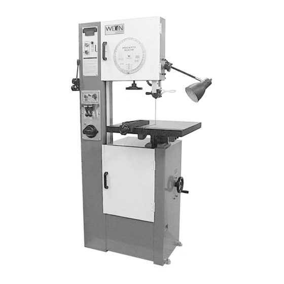
Models 8014FW and 8020FW
Model 8014FW
Model 8020FW
WMH TOOL GROUP
2420 Vantage Drive
Elgin, Illinois 60123
Part No. M-8014FW
Ph.: 800-274-6848
Revision A 6/05
www.wmhtoolgroup.com
Copyright © WMH Tool Group
Advertisement
Table of Contents

Related Manuals for Wilton 8014FW


Summary of Contents for Wilton 8014FW
- Page 1 This Manual is Bookmarked Operating Instructions and Parts Manual 14- & 20-inch Metalworking Band Saws Models 8014FW and 8020FW Model 8014FW Model 8020FW WMH TOOL GROUP 2420 Vantage Drive Elgin, Illinois 60123 Part No. M-8014FW Ph.: 800-274-6848 Revision A 6/05 www.wmhtoolgroup.com...
-
Page 2: Warranty And Service
This manual has been prepared for the owner and operators of a Wilton 8014FW or 8020FW Band Saw. Its purpose, aside from machine operation, is to promote safety using accepted operating and maintenance procedures. To obtain maximum life and efficiency from your band saw and to aid in using it safely, please read this manual thoroughly and follow the instructions carefully. -
Page 3: Table Of Contents
Parts List: Band Saw Assembly (8014FW only) ..................30 Band Saw Assembly (8014FW only)....................35 Parts List: Welder, Shear and Work Lamp Assemblies (8014FW only)..........36 Welder, Shear and Work Lamp Assemblies (8014FW only) ..............39 Parts List: Band Saw Assembly (8020FW only) ..................40 Band Saw Assembly (8020FW only)....................47... -
Page 4: Warning
Warning 1. Read and understand the entire owners manual before attempting assembly or operation. 2. Read and understand the warnings posted on the machine and in this manual. Failure to comply with all of these warnings may cause serious injury. 3. -
Page 5: Save These Instructions
blahblahblah 21. Give your work undivided attention. Looking around, carrying on a conversation and “horse-play” are careless acts that can result in serious injury. 22. Maintain a balanced stance at all times so that you do not fall or lean against the blade or other moving parts. -
Page 6: Introduction
This manual is provided by WMH Tool Group covering the safe operation and maintenance procedures for a Wilton Model 8014FW or 8020FW Band Saw. This manual contains instructions on installation, safety precautions, general operating procedures, maintenance instructions and parts breakdown. This machine has been designed and constructed to provide years of trouble free operation if used in accordance with instructions set forth in this manual. -
Page 7: Features And Terminology
Features and Terminology 1 – Variable Speed Handwheel 12 – Lower Door 2 – Fence 13 – Pressure Selector Switch 3 – Work Lamp 14 – Anneal Button 4 – Chip Blower Hose 15 – Weld Button 5 – Guide Post Lock Knob 16 –... -
Page 8: Unpacking
Contents of the Shipping Container Unpacking Band Saw Open shipping container and check for shipping Fence damage. Smaller parts are found in a separate Knob box at the foot of the band saw. Report any Shear damage immediately to your distributor and shipping agent. -
Page 9: Installation And Assembly
Installation and Assembly Tools required for assembly: Forklift or hoist with strap or chain Set of hex wrenches (provided) Remove all crating and plastic from around the band saw. Remove any lag screws or holding straps which secure the saw to the wood pallet. Remove the eye bolt from the tool box, and screw it into the hole at the top of the machine. -
Page 10: Test Run
Improper connection equipment- grounding conductor can result in a risk of electric shock. The conductor with insulation having an outer surface that is green with or without yellow stripes, is the equipment- grounding conductor. If repair or replacement of the electric cord or plug is necessary, do not connect the equipment-grounding conductor to a live terminal. -
Page 11: Adjustments
Adjustments [NOTE: Procedures for the model 8014FW and the model 8020FW are identical except where noted.] Blade Removal and Installation Wear leather gloves when removing or installing band saw blades. New blades usually come in a coiled position; to prevent injury, hold the blade with one hand while carefully uncoiling it with the other. -
Page 12: Blade Tracking
5. If the blade tracks improperly, use the screws at the back of the saw (Figure 6) to adjust the model 8014FW. Loosen the socket head cap screws as needed to allow adjustment of the set screws. -
Page 13: Squaring Work Table With Blade
3. Tighten the socket head cap screws securely. 4. This procedure should be done for both upper and lower guide housings. 5. Open upper door and rotate the wheel by hand until the weld portion of the blade is between the two blade guides. 6. -
Page 14: Replacing Drive Belts
(see above). Then lift up on the variator pulley Figure 13 (Figure 13) to slacken the belt. (Model 8014FW) 5. After installing new belts, make sure they are tensioned properly and all screws or nuts are re-tightened. -
Page 15: Setting Blade Speed
Cutting Efficiency” below). Allow the saw to complete the cut. Figure 14 6. The blade is now considered ready for use. (Model 8014FW only) Setting Blade Speed 1. Consult the Speed and Pitch selection chart on the front of the band saw. A chart is also included on page 23 of this manual. -
Page 16: Welder Operation
Welder Operation Wear eye protection while operating welder. care when handling the blade after welding to avoid burns. The welding procedure involves the following steps: Shearing the blade, grinding teeth to allow for the weld area, the actual welding, inspection of the blade, annealing, grinding and a final inspection of the blade. -
Page 17: Annealing
5. Turn pressure knob to “0” position (pointed downward). NOTE: There will be some resistance when turning the knob. 6. Insert one end of the blade in the left clamp (Figure 19). Position the back edge of the blade against the back edge of the left clamp. - Page 18 14. Turn the pressure selector knob all the way to the left so the clamp jaws are closest to each other. 15. Insert the blade into the clamps so the weld area is centered between the clamps. Secure the blade in the jaws with the clamp handles.
-
Page 19: Blade Selection
If the blade is thicker at the weld than at the rest of the blade, using the blade may damage the guides. 20. When grinding, do not hit the teeth, or grind deeper than the thickness of the blade; or burn or overheat the weld area. -
Page 20: Gage
Gage Use the standard gage (blade thickness) except when the increased thickness of the workpiece decreases accuracy and width cannot be increased to compensate. Examples of heavy gage applications: 1. When radius cutting in thick materials. 2. When the maximum width usable on the machine still provides insufficient beam strength for the blade. -
Page 21: Set
The Hook blade has larger teeth and gullets and a positive rake angle which permits better feed and chip removal. It is useful for both cast iron as well as hard, nonferrous alloys. Variable-tooth blades combine features of the other styles. They generally offer smooth cuts and long blade life, while reducing noise and vibration. - Page 22 Make sure the chip brush on the lower band Maintenance wheel is properly adjusted. If the power cord is worn, cut, or damaged in Before doing maintenance on any way, have it replaced immediately. the machine, disconnect it from the electrical supply by pulling out the plug or switching The chart (Figure 28) identifies areas that off the main switch! Failure to comply may...
-
Page 23: Speed And Pitch Chart
Speed and Pitch Chart... -
Page 24: Typical Band Saw Operations
Typical Band Saw Operations... - Page 25 Troubleshooting – Operating Problems Trouble Probable Cause Remedy Re-weld the blade (see page 16- Blade has been improperly welded. 19). Set the blade guides closer, and Blade not installed properly. Saw blade is increase blade tension. twisted. Feeding workpiece too forcefully. Decrease feed rate.
-
Page 26: Troubleshooting - Mechanical And Electrical Problems
Troubleshooting – Mechanical and Electrical Problems Trouble Probable Cause Remedy Machine will not Verify machine is connected to start/restart or power source. Make sure START No incoming power. repeatedly trips button is pushed in completely, and circuit breaker or the STOP button is disengaged. blows fuses. - Page 27 Trouble Probable Cause Remedy If electric motor is suspect, you have two options: Have a qualified electrician test the motor for Motor failure. Machine will not function or remove the motor and start/restart or take it to a qualified electric motor repeatedly trips repair shop and have it tested.
- Page 28 Troubleshooting – Welded Blade Inspection Trouble Probable Cause Remedy Weld is misaligned. Dirt or scale on clamp jaws or Always keep jaws clean. Clean blade. blade before welding. Before welding, grind cut edges of the blade until they are square. Use Blade ends not square.
-
Page 29: Replacement Parts
Troubleshooting – Welder Mechanical Problems Trouble Probable Cause Remedy Wire connection is poor; connecting Change switch, or grind the point of welding switch is bad. connecting port with a file. Weld could not be Transformer burnt out. Change transformer, or re-wire it. made. -
Page 30: Parts List: Band Saw Assembly (8014Fw Only)
26..... TS-0680031 .... Flat Washer............5/16"......2 27..... VBS16-155 ..... Rip Fence..................... 1 28..... 8014FW-128 ... Tilt Indicator (Left & Right) ..............1 29..... 8771 ....... Tilt Indicator (Forward & Back).............. 1 30..... 9700 ....... Indicator Needle ................... 2 31..... - Page 31 109... TS-0208031 .... Socket Head Cap Screw........5/16-18 x 5/8" ..... 1 110... 9600 ....... Chip Stopper ..................1 111... 8014FW-1111 ..Pan Head Bolt ........... 8 x 12mm ....2 112... 9780 ....... Brusher Bracket..................1 113... 8014FW-1113 ..Pan Head Bolt ........... 8 x 12mm ....1 114...
- Page 32 125... TS-0050011 .... Hex Cap Screw..........1/4-20 x 1/2" ....1 126... 4050 ....... Air Pump Leaf..................4 127... 8014FW-1127 ..Air Pump Suspend Arm ................ 1 128... TS-0051051 .... Hex Cap Screw..........5/16-18 x 1" ....2 129...
- Page 33 196... TS-1551041 .... Lock Washer ............. 6mm......2 197... TS-1540041 .... Hex Nut ............. 6mm......2 198... 8014FW-1198 ..Speed and Pitch Selector (1) ..............1 199... 8014FW-1199 ..Speed and Pitch Selector (2) ..............1 200... 8014FW-1200 ..Speed and Pitch Selector (3) ..............1 201...
- Page 34 255... VBS16-7500 ... Inner Pulley ..................1 256... VBS16-7510 ... Middle Pulley..................1 257... 8014FW-1257 ..Oil Seal ............. 26x 19x5mm ..1 258... VBS16-7520 ... Outer Pulley..................1 259... TS-2236911 .... Socket Head Cap Screw........M6x100 ...... 3 260...
-
Page 35: Band Saw Assembly (8014Fw Only)
Band Saw Assembly (8014FW only) -
Page 36: Parts List: Welder, Shear And Work Lamp Assemblies (8014Fw Only)
(refer to breakdown on page 39) Index No. Part No. Description Size 2....8014FW-22 ..... Pan Head Bolt ........... #5 x 5/8" ..... 2 3....8014FW-23 ..... Lock Washer ............. #5....... 2 4....PR-EV-6011.... Insulator ....................1 5....PR-EV-6020.... Guide Block..................1 6.... - Page 37 57..... PR-EV-6220.... Short Spring ..................1 58..... 8014FW-258 ... Pan Head Bolt ........... 5 x 6mm ..... 2 59..... TS-1551031 .... Lock Washer ............. 5mm......2 60..... PR-EV-6230.... Spring, Long..................1 61..... PR-EV-6240.... Transformer..................1 62..... 8014FW-262 ... Copper Pan Head Bolt........3/16 x 3/8" ....2 63.....
- Page 38 117... PR-EV-1920.... Spindle Lift ................... 1 118... 8014FW-2118 ..Retaining Ring........... 25mm ......2 119... PR-EV-1930.... Blade Shaft................... 1 120... 8014FW-2120 ..Retaining Ring........... 5mm......2 121... PR-EV-1940.... Vaned Iron Plate................... 2 122... TS-081C022 ... Phillips Pan Head Machine Screw...... #10-24 X 3/8"....4 123...
-
Page 39: Welder, Shear And Work Lamp Assemblies (8014Fw Only)
Welder, Shear and Work Lamp Assemblies (8014FW only) -
Page 40: Parts List: Band Saw Assembly (8020Fw Only)
Parts List: Band Saw Assembly (8020FW only) (refer to breakdowns on pages 47-48) Index No. Part No. Description Size 1....VBS2012-0500..Gear Box ....................1 2....TS-0209091 .... Socket Head Cap Screw........3/8-16 x 2” ....4 3....TS-0720091 .... Lock Washer ............. 3/8”......4 4.... - Page 41 56..... TS-0680042 .... Flat Washer............3/8”......2 57..... 8020FW-157 ... Left Table Bracket ................1 58..... TS-0060091 .... Hex Cap Screw..........3/8-16 x 2” ....2 59..... TS-0720091 .... Lock Washer ............. 3/8”......2 60..... TS-0680042 .... Flat Washer............3/8”......2 61.....
- Page 42 116... VBS2012-9015..Guide Post Lock ................... 1 117... VBS2012-9033..Post Elevating Handwheel ..............1 118... TS-0270111 .... Socket Set Screw ..........5/16-18 x 1/2” ..... 1 119... 8020FW-1119 ..Handle Knob..................1 120... VBS2012-G6201..Ball Bearing..................1 121...
- Page 43 176... VBS2012-9790..Chip Stopper ..................1 177... TS-0050031 .... Hex Cap Screw..........1/4-20 x 3/4” ....1 178... TS-0680021 .... Flat Washer............1/4”......1 179... 8020FW-1179 ..Ball Bearing..................2 180... VBS2012-4010..Air Pump Housing................. 1 181... VBS2012-4020..Air Pump Cover ..................1 182...
- Page 44 236... VBS2012-9500..Spring Plate..................2 237... TS-1533032 .... Phillips Pan Head Machine Screw...... 5 x 10mm ....4 238... TS-1551031 .... Lock Washer ............. 5mm......4 239... TS-1540031 .... Hex Nut ............. 5mm......4 240... TS-1533032 .... Phillips Pan Head Machine Screw...... 5 x 10mm ....2 241...
- Page 45 296... VBS2012-7010..Spring....................1 297... VBS2012-7020..Variable Speed Disc – Upper Outside........... 1 298... TS-0208041 .... Socket Head Cap Screw........5/16-18 x 3/4” ..... 1 299... VBS2012-7030..Variable Speed Disc – Upper Inside............1 300... VBS2012-7040..Variable Speed Housing Tube .............. 1 301...
- Page 46 356... 8020FW-1356 ..Brass Handle..................1 357... 8020FW-1357 ..Selector Bushing .................. 1 358... TS-1550011 .... Flat Washer............3mm......1 359... 8020FW-1359 ..Lock Washer ............. 3mm......1...
-
Page 47: Band Saw Assembly (8020Fw Only)
Band Saw Assembly (8020FW only) -
Page 48: Band Saw Assembly (8020Fw Only)
Band Saw Assembly (8020FW only) -
Page 49: Parts List: Welder, Shear And Work Lamp Assemblies (8020Fw Only)
60 .....PR-EV-6230.... Long Spring ..................1 61 .....VBS1220M-624..Transformer..................1 62 .....8014FW-262 ... Copper Pan Head Bolt ........3/16 x 3/8” ....2 63 .....TS-0720051 .... Lock Washer............#10 ......2 64 .....8020FW-264 ... Mounting Bracket.................. 4 65 .....TS-1513021 .... - Page 50 115 ...TS-0720071 .... Lock Washer............1/4”......1 116 ...TS-0561011 .... Hex Nut ............. 1/4-20 ......1 117 ...PR-EV-1920.... Spindle Lift.................... 1 118 ...8014FW-2118 ..Retaining Ring ........... 25mm ......2 119 ...PR-EV-1930.... Blade Shaft................... 1 120 ...8014FW-2120 ..Retaining Ring ........... 5mm ......2 121 ...PR-EV-1940....
- Page 51 55 .....TS-081F052 .... Phillips Pan Head Machine Screw...... 1/4-20 x 3/4 ....1 56 .....PR-EV-6211.... Bushing ....................1 57 .....PR-EV-6220.... Short Spring ..................1 58 .....8014FW-258 ... Phillip Pan Head Machine Screw ....... 5 x 6mm ..... 2 59 .....TS-1551031 .... Lock Washer............5mm ......2...
-
Page 52: Welder, Shear And Work Lamp Assemblies (8020Fw Only)
Welder, Shear and Work Lamp Assemblies (8020FW only) -
Page 53: Electrical Connections - Model 8014Fw Only
Electrical Connections – Model 8014FW only... -
Page 54: Electrical Connections - Model 8020Fw Only
Electrical Connections – Model 8020FW only... - Page 56 WMH Tool Group 2420 Vantage Drive Elgin, Illinois 60123 Phone: 800-274-6848 www.wmhtoolgroup.com...
Need help?
Do you have a question about the 8014FW and is the answer not in the manual?
Questions and answers