Table of Contents
Advertisement
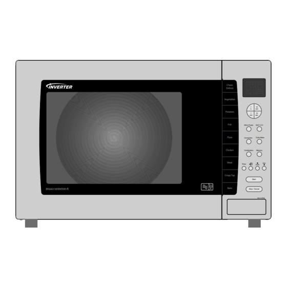
Power source
Power requirements
Output (IEC60705)
Microwave frequency
Timer
Oven cavity size
Outside dimensions
Inside dimensions
Weight
NN-CT878SBPQ
32L
Chaos
Defrost
United Kingdom
Vegetables
1
10
h
min
Potatoes
1
10
min
sec
Fish
Micro Power
Grill 1-2-3
Pizza
Convection
Turbo-Bake
Chicken
Combination
Memory
Meat
less
Timer
more
Crispy Top
Start
Bake
Stop / Cancel
NN-CT878S
240V AC Single Phase 50Hz
Microwave 1220W
Grill 1560W
Convection 1350W
Combi 2870W
Microwave 1000W
Grill 1500W
Convection 1250W
99 min 99 second
530mm(W) x 508mm(D) X 344MM (H)
350mm(W) X 360mm(D) x 250mm(H)
© 2007 Matsushita Electric Industrial Co., Ltd. All rights reserved.
Unauthorized copying and distribution is a violation of law.
Microwave Oven
2450Mhz
32L
21Kg
HAD0712001C2
Advertisement
Table of Contents
Troubleshooting

Related Manuals for Panasonic NN-CT878SBPQ


Summary of Contents for Panasonic NN-CT878SBPQ
-
Page 1: Microwave Oven
HAD0712001C2 Microwave Oven NN-CT878SBPQ Chaos Defrost United Kingdom Vegetables Potatoes Fish Micro Power Grill 1-2-3 Pizza Convection Turbo-Bake Chicken Combination Memory Meat less Timer more Crispy Top Start Bake Stop / Cancel NN-CT878S Power source 240V AC Single Phase 50Hz... -
Page 2: Table Of Contents
NN-CT878SBPQ 1 Contents Contents ............2 Inverter Warnings . -
Page 3: Inverter Warnings
NN-CT878SBPQ 2 Inverter Warning The inverter board looks like a regular PCB, however, this PCB drives the magnetron tube using very high voltages and cur- rent. It has 1. Very high voltage and high current 2. An Aluminium heat sink that becomes very hot 3. -
Page 4: Control Panel
NN-CT878SBPQ 4 Control Panel... -
Page 5: Operation And Digital Programmer Circuit Test Procedure
NN-CT878SBPQ 5 Operation And Digital Programmer Circuit Test Procedure... - Page 6 NN-CT878SBPQ...
- Page 7 NN-CT878SBPQ...
-
Page 8: Schematic Diagram
NN-CT878SBPQ 6 Schematic Diagram... -
Page 9: Wiring Diagram
NN-CT878SBPQ 7 Wiring Diagram Wiring Harness... -
Page 10: Description Of The Operation Sequence
NN-CT878SBPQ 8 Description of Operating instruction 8.1. Variable power cooking control 8.3. Auto weight defrost, Auto weight Cook The HIGH VOLTAGE INVERTER POWER SUPPLY controls the output power by a signal from the digital Programmer circuit When an auto control feature is selected and the start pad DPC. -
Page 11: Convection Cooking
NN-CT878SBPQ 8.4. Convection Cooking 1. The digital programmer circuit operates the power relays temperature, the digital programmer circuit supplies RY3,RY5 and RY6 in the sequence as shown in the figure power to power relay RY5 resulting in the convection below. -
Page 12: Combination Cooking
NN-CT878SBPQ 8.5. Combination Cooking Convection And Microwave Combination Duty Cycles Convection Heater Micropower Combination cooking is achieved by operating the microwave 100 - 250 C DISPLAY OUTPUT and heater modes together during one cooking cycle. There 360W are three combination modes. - Page 13 NN-CT878SBPQ 8.5.1 convection and microwave duty cycles Figure 1...
- Page 14 NN-CT878SBPQ 8.5.2 grill and microwave duty cycles Figure 2...
- Page 15 NN-CT878SBPQ 8.5.3 Grill,Convection and microwave duty cycles Figure 3...
- Page 16 NN-CT878SBPQ 8.6. One touch Auto sensor cooking Auto sensor cook is a revolutionary way to cook by microwave without setting a power level or selecting a time. All that is nec- Category P1 POWER P2 POWER K FACTOR essary is to select an auto sensor program before starting to STANDARD cook.
-
Page 17: Cautions To Be Observed When Troubleshooting
NN-CT878SBPQ 9 Cautions to Be Observed When Troubleshooting Unlike many other appliances, the microwave oven is a high voltage, high current device. Although it is free from danger in ordinary use, extreme care should be taken during repair. Caution Servicemen should remove their watches whenever working close to or replacing the magnetron. - Page 18 NN-CT878SBPQ Inverter Grounding Figure 2 Discharging the high voltage capacitors Figure 3 WARNING! DISCHARGE THE HIGH VOLTAGE CAPACITORS For about 30 seconds after the oven is turned off, an elec- tric charge remains in the high voltage capacitors in the inverter power supply circuit board.
-
Page 19: Confirm After Repair
NN-CT878SBPQ 9.3. When parts must be replaced, 9.6. Confirm after repair remove the power plug from 1. After repair or replacement of parts, make sure that the screws of the oven, etc. are neither loose nor missing. the outlet. Microwaves might leak if screws are not properly tight- ened. -
Page 20: Part Replacement Procedure
NN-CT878SBPQ 10 Parts Replacement Procedure 10.1. Magnetron 1. Discharge the high voltage capacitors on the inverter cir- cuit. 2. Remove the five screws shown in figure 1 3. Disconnect the two high voltage leads from the magne- tron 4. Remove the four screws holding the magnetron as shown... - Page 21 NN-CT878SBPQ 3. Securely connect the 3 lead wire connectors 4. Make sure that the heat sink has enough space (gap) from the oven. Take care not to touch any lead wire to the aluminium heat sink because it is hot.
- Page 22 NN-CT878SBPQ Disconnecting the PCB lock connector Removal of DPC AU and DPC HU Figure 4 Figure 5 10.3. Digital Programmer Circuit (DPC) membrane board. NOTE: Ground any static electric built up on your body before handling the DPC. 1. Disconnect all connectors from the DPC.
-
Page 23: Fan Motor
NN-CT878SBPQ 10.5. Fan Motor proper installation and adjustment so as to prevent exces- sive microwave leakage. 1. Disconnect the two lead wires from the fan motor termi- 1. When mounting the door to the oven, be sure to adjust nals the door parallel to the bottom line of the oven face plate 2. -
Page 24: Quartz Heater
NN-CT878SBPQ Note: After breaking off the motor cover, make sure that cut-off portions are properly trimmed off or bent inside so that no sharp edges are exposed. Note: To secure the motor cover use a 4 x 6 screw. Two screws to remove the turntable motor... - Page 25 NN-CT878SBPQ Removing the screws holding the grill heater Figure 11 Removing the grill element Figure 12...
- Page 26 NN-CT878SBPQ 10.9. Convection Element And Circulation Fan Motor 1. Remove one screw to remove the exhaust guide D. Figure 13. 2. Remove the rear heater cover by removing the three screws. Figure 13 3. Remove the temperature sensor by removing the two screws. Figure 14 4.
- Page 27 NN-CT878SBPQ Removing the oven back plate Figure 14 Removing the base plate Figure 15...
- Page 28 NN-CT878SBPQ Removing the circulation motor Figure 16...
-
Page 29: Component Test Procedure
NN-CT878SBPQ 11 Component Test Procedure Caution 1. High voltage is present at the high voltage terminal of the inverter unit, including the aluminium heat sink. 2. It is not necessary or advisable to attempt to measure this high voltage. 3. Before touching any oven components, or wiring, always unplug the oven from its power source and discharge the high voltage capacitors. - Page 30 NN-CT878SBPQ 11.5. Inverter Power Supply Caution DO NOT try to repair this inverter power supply. Replace as a whole H.V. Inverter Unit. Inverter power supply diagram Figure 3 11.6. Inverter Power Supply Unit sor is working, perform the following test.
-
Page 31: Measurements And Adjustments
NN-CT878SBPQ 12 Measurements and Adjustments Warning • For continued protection against radiation hazard, replace only with identical parts. • When the 10 amp fuse is blown due to the operation of the short switch, you must replace the primary latch switch and short switch. -
Page 32: Troubleshooting Guide
NN-CT878SBPQ 13 Troubleshooting Guide... - Page 33 NN-CT878SBPQ Fuses are blown Fuses are not blown Checking the semiconductors using a resistance meter...
- Page 34 NN-CT878SBPQ Other problems Inverter circuit troubleshooting 6A5BPQ Alternative method for toubleshooting, the inverter circuit Alternate way to troubleshoot oven with AC Ampere meter used H95, H97, H98, H99 appears in display window a short time after start key is pressed and no microwave oscillation with AC Ampere...
-
Page 35: Description Of Operating Instruction
NN-CT878SBPQ 14 Description of Operating instruction 14.1. Auto weight defrost, Auto weight Cook When an auto control feature is selected and the start pad pressed: 1. The digital programmer circuit determines the power level and the cooking time and indicates the operating state in the display.
Need help?
Do you have a question about the NN-CT878SBPQ and is the answer not in the manual?
Questions and answers