
Related Manuals for McQuay Skyline IM777


Summary of Contents for McQuay Skyline IM777
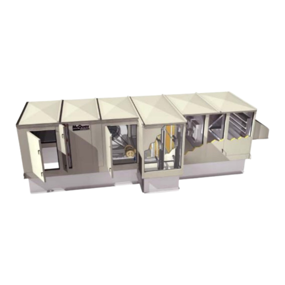
- Page 1 Installation and Maintenance Manual IM777 Group: Applied AIr Part Number: IM777 Date: April 2003 Skyline Outdoor Air Handler Sizes 003 - 055 © 2003 McQuay International IM777 Page 1...
-
Page 2: Table Of Contents
Table of Contents Nomenclature ..............2 Electrical Installation .............12 General Information ............3 Operation Guidelines ............13 Receiving and Handling ..........3 Startup Checks ...............13 Unit Storage ..............3 Fan Wheel Alignment ............14 Installation Guidelines ............4 Fan Operating Limits .............16 Service Clearances ............ -
Page 3: General Information
General Information Receiving and Handling The system design and installation must follow accepted industry practice, such as described in the ASHRAE Hand- 1. Carefully check items against the bills of lading to verify book, the National Electric Code, and other applicable stan- all crates and cartons have been received. -
Page 4: Installation Guidelines
Installation Guidelines Service Clearances Figure 2. Service clearance for electrical power devices In addition to providing adequate space around the unit for piping coils and drains, access is always required on at least one side of the unit to allow for regular service and mainte- nance. -
Page 5: Curb Mounting And Leveling
Curb Mounting and Leveling Figure 5. Apply sealant to mating faces Do not place a Skyline unit over an open curb unless it is equipped with a curb-ready base. Installation instructions for mounting units on a roof curb are provided in IM770. For a copy, contact your local McQuay Representative or visit www.mcquay.com. -
Page 6: Access Doors And Panels
Figure 7. Internal fastening flanges. Bend the ends of the splice cap down to secure in place. Assemble the small splice plate at the top rail to secure the sections together at the top. Use 5/16" bolts. See Figure 9. Figure 9. -
Page 7: Duct Connections
Figure 10. Opening fan section door Figure 12. Flashing over top panels and sides of units . l a s h i n g . l a s h i n g U n i t t o p Do Not Rotate Cup p a n e l D u c t . -
Page 8: Mounting Actuators
Figure 14. Field installed barrier between hoods Piping Vestibules The openings for routing the field piping must be cut as required in the field for units that include a piping vestibule. Carefully seal passages cut through the panels to prevent air leakage. -
Page 9: Direct Expansion Coils
Water Cooling Coils atmosphere, and the trap design should allow venting of large quantities of air. Note:It is recommended that Glycol be used in water coils for outdoor air handlers. Power failures and other mechani- 7. Do not drip supply mains through the coil. cal issues can expose coils to freezing temperatures. - Page 10 Figure 17. Piping arrangements Control valve Float and modulating Check Valve Strainer Gate Valve thermostatic trap two position High pressure (over 25 psi) Vacuum breaker Steam main Steam main 1/2" check valve Vacuum breaker 1/2" check valve Return main 1/4" petcock 1"...
-
Page 11: Drain Pan Traps
Water heating coils Figure 19. Extend drain fitting for door clearance 1. Water supply and water return connections extend through the end panel of the coil section. All connections are labeled on the end panel. 2. Water supply and water return connections are male N.P.T. -
Page 12: Electrical Installation
Figure 20. Removing shipping brackets Electrical Installation 1. Electrical service to the fan must correspond to the rated voltage on the motor nameplate and be in conformance with the National Electric Code and local restrictions. 2. The fan section metal frame must be connected to the building electrical ground. -
Page 13: Operation Guidelines
Operation Guidelines Startup Checks When performing startup and service, thorough safety ATTENTION precautions must always be taken. These functions must Risques de dommages dans le moteur du ventilateur be performed by trained, experienced personnel. électrique. Si Ia température de l'air a proximité du ventilateurest élevée, le moteurdu ventilateur électrique peut chauffer et brûler. -
Page 14: Fan Wheel Alignment
Fan Wheel Alignment Table 2: Wheel-to-inlet funnel relationship — Table 3: Wheel-to-inlet funnel relationship — airfoil type fan wheels (housed) forward curved type fan wheels (housed) Equal spacing Wheel all around Inlet Inlet Funnel Funnel AIRFOIL FORWARD CURVED Unit Sizes 003-055 Unit Sizes 003-055 Diameter A (inches) - Page 15 Table 4: Wheel-to-inlet funnel relationship - plenum fans Table 5: Wheel-to-inlet funnel relationship - inline fans OVERLAP OVERLAP WHEEL — FUNNEL OVERLAP WHEEL — FUNNEL OVERLAP SIZE OVERLAP SIZE OVERLAP .120 .375 .190 .438 16.5 .250 .562 18.25 .310 .625 .380 .688 22.25...
-
Page 16: Fan Operating Limits
Fan Operating Limits Do not exceed the operating limits in Table 7. A fan wheel that distortion or fracture. The resulting unbalance may cause is operated beyond the rpm limits shown may suffer permanent severe unit vibration. Table 7: Operating limits - housed fans FAN OPERATING LIMITS Forward curved —... -
Page 17: Fan Vibration Levels
Figure 24. Torque requirements at 100% WOV for SWSI plenum fans with NESTED inlet vane 5000 4000 3000 2000 1000 Fan Speed (rpm) Table 9: Operating limits — inline fans, twin fans FAN OPERATING LIMITS Inline Fans Diameter Maximum RPM Class I 2727 2488 2236... -
Page 18: Service And Maintenance
Service and Maintenance Periodic Service and Maintenance Fan Drive Adjustments 1. Check all moving parts for wear every six months. 2. Check bearing collar, sheave, and wheel hub setscrews, WARNING sheave capscrews, and bearing hold-down bolts for tight- ROTATING FAN ness every six months. - Page 19 Adjusting: c. Remove key "F". Note: This key projects a small 1. Loosen setscrews "B" and "C" in moving parts of sheave amount to provide a grip for removing. and pull out external key "E". (This key projects a small d.
- Page 20 Figure 26. "LVP" type sheave adjustment "MVP" Variable Speed Sheaves sheave pitch. Do not operate the drive until the locking screws have been set to the torque specifications. Mounting: 1. Verify both driving and driven sheaves are in alignment Table 12: Screw torque values and the shafts are parallel.
-
Page 21: Drive Belt Adjustment
Figure 28. Sheave adjustment Fixed (2) Locking Flathead Socket Screws Adjustable Center-Flange Setscrews "A" (Do Not Remove) Center-Flange Split Taper Bushing Outer (3) Holes for Locking-Ring Spanner Wrench Stationary Capscrews or Drift Inner Locking-Ring End-Flange (Do Not Remove) Drive Belt Adjustment Tension Measurement Procedure 1. -
Page 22: Front Load Filter Option
Table 13: Belt deflection force SHEAVE DIAMETER (INCHES) DEFLECTION FORCE (LBS.) BELT DEFLECTION FORCE CROSS SECTION SMALLEST SHEAVE RPM RANGE CROSS SECTION A, B, 5V CROSS SECTION AX, BX, 5VX DIAMETER RANGE USED BELT NEW BELT USED BELT NEW BELT 1000-2500 3.0-3.6 2501-4000... -
Page 23: Winterizing Water Coils
Winterizing Water Coils Table 14 shows the typical filter pressure drop for clean filters at rated air flow and a final pressure drop for front loaded filters. Coil freeze-up can be caused by such things as air stratifica- Table 14: Filter pressure drops tion and failure of outdoor dampers and/or preheat coils. -
Page 24: Component Removal & Replacement
Component Removal & Replacement Figure 31. Single coil installation / removal See “Access Doors and Panels” on page 6 for instructions on removing panels and opening fan access doors to remove or Connection end Opposite connection end replace components. Coil Fan Section The fan shaft, motor, and any drive components can be removed and replaced through the access door opening. - Page 25 Removing and Installing Staggered Coils 5. Caulk the seams between the coil casings and blockoffs. Staggered coils have two banks of coils positioned a few 6. Connect all piping and install the brass plugs for the vents inches apart in the direction of airflow. Both coils are secured and drains located in the connections.
-
Page 26: Warranty
Warranty The return of the part does not constitute an order for replacement. Therefore, a purchase order must be entered through the nearest McQuay representative. The order should Consult your local McQuay Representative for warranty include part number, model number, and serial number of the details. - Page 27 Notes: IM777 Page 27...
- Page 28 This document contains the most current product information as of this printing. For the most up-to-date product information, please go to www.mcquay.com. © 2003 McQuay International • www.mcquay.com • 800-432-1342 Page 28 IM777...
Need help?
Do you have a question about the Skyline IM777 and is the answer not in the manual?
Questions and answers