Advertisement
Advertisement
Table of Contents

Related Manuals for McQuay MDM Series


Summary of Contents for McQuay MDM Series
- Page 1 CMDM - 2004 McQuay MDM Air Handling Unit...
-
Page 2: Table Of Contents
“McQuay” is a registered trademark of McQuay International. All rights reserved throughout the world. © 2003 McQuay International “Bulletin illustration cover the general appearance of McQuay International products at the time of publication and we reserve the right to make change in design and construction any time without notice”... -
Page 3: Nomenclature System
Orientation of the Pipe Connection L – Left Connection R – Right Connection Width Modulus of the Unit Height Modulus of the Unit McQuay Double-Skinned Modulus Air Handling Unit Type MDM air handling units: • Total 123 unit sizes •... -
Page 4: Features
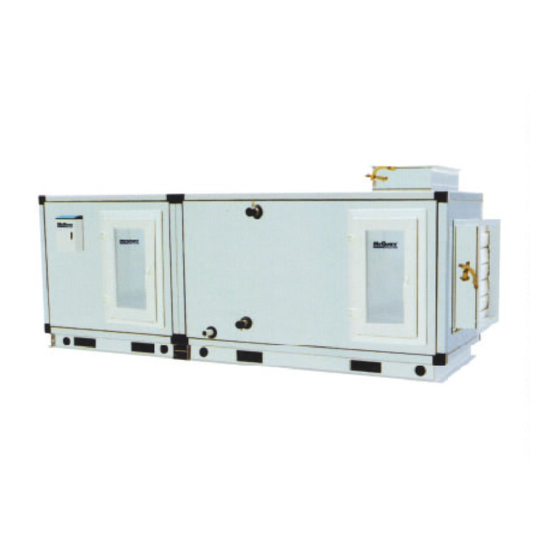
Improved Indoor Air Quality Designed to be as easy to maintain, as it is to install, the McQuay MDM Air Handling Unit offers extended coil connections and hinged access doors, or lift off panels. Unit sections can be thoroughly cleaned to reduce the potential for indoor air quality problems. - Page 5 Internal isolation provides an opportunity for significantly reduced installation costs. McQuay also can provide function such as mixing section, exhaust section, access section, attenuation section, humidifier section, electric heating section, heating coil section, secondary mixing section, distribution and heat recovery section, etc.
-
Page 6: Performance Tables
Performance Tables... - Page 8 The Cooling Performance Data Table Based On Return-Air Mode (I) COIL TYPE (4 ROWS / 12 FPI) PIPE FACE VELOCITY - 2.5m/s FACE VELOCITY - 2.75m/s MODEL CIRCUIT connection W.P.D W.P.D m³/h m³/h 0306 2030 0.64 10.33 13.82 2233 0.68 11.11 14.71 0308...
- Page 9 The Cooling Performance Data Table Based On Return-Air Mode (II) COIL TYPE (6 ROWS / 12 FPI) PIPE FACE VELOCITY - 2.5m/s FACE VELOCITY - 2.75m/s MODEL CIRCUIT connection W.P.D W.P.D m³/h m³/h 0306 2030 0.83 16.9 12.03 17.78 2233 0.90 19.5 13.03...
- Page 10 The Cooling Performance Data Table Based On Return-Air Mode (III) COIL TYPE (8 ROWS / 12 FPI) PIPE FACE VELOCITY - 2.5m/s FACE VELOCITY - 2.75m/s MODEL CIRCUIT connection W.P.D W.P.D m³/h m³/h 0306 2030 0.93 27.1 13.00 20.00 2233 1.00 30.8 14.10...
- Page 11 The Cooling Performance Data Table Based On Fresh-Air Mode (I) COIL TYPE (4 ROWS / 12 FPI) PIPE FACE VELOCITY - 2.5m/s FACE VELOCITY - 2.75m/s MODEL CIRCUIT connection W.P.D W.P.D m³/h m³/h 0306 2030 1.60 36.6 13.89 33.62 2233 1.68 39.8 14.81...
- Page 12 The Cooling Performance Data Table Based On Fresh-Air Mode (II) COIL TYPE (6 ROWS / 12 FPI) PIPE FACE VELOCITY - 2.5m/s FACE VELOCITY - 2.75m/s MODEL CIRCUIT connectio W.P.D W.P.D n BSP m³/h m³/h 0306 2030 1.80 25.1 15.72 38.43 2233 1.95...
- Page 13 The Cooling Performance Data Table Based On Fresh-Air Mode (III) COIL TYPE (8 ROWS / 12 FPI) PIPE FACE VELOCITY - 2.5m/s FACE VELOCITY - 2.75m/s MODEL CIRCUIT connection W.P.D W.P.D m³/h m³/h 0306 2030 2.00 38.5 17.36 42.33 2294 2.18 44.8 18.81...
- Page 14 The Heating Performance Data Table Based On Return-Air Mode RETURN-AIR MODE (2 ROWS / 12 FPI) PIPE FACE VELOCITY - 2.5m/s FACE VELOCITY - 2.75m/s MODEL CIRCUIT connection W.P.D A.P.D W.P.D A.P.D m³/h m³/h 0306 2030 0.32 80.1 2233 0.335 0308 2908 0.48...
- Page 15 The Heating Performance Data Table Based On Fresh-Air Mode RETURN-AIR MODE (2 ROWS / 12 FPI) PIPE FACE VELOCITY - 2.5m/s FACE VELOCITY - 2.75m/s MODEL CIRCUIT connection W.P.D A.P.D W.P.D A.P.D m³/h m³/h 0306 2030 0.76 80.1 2233 0.81 0308 2908 1.13...
- Page 16 The Motor Power Table MOTOR POWER (kW) MODEL MDM ESP(300Pa) ESP(500Pa) 4 ROWS 6 ROWS 8ROWS 4 ROWS 6 ROWS 8ROWS 0306 0.75 0308 0.55x2 0.55x2 0.75x2 0.75x2 0.75x2 1.1x2 0408 0410 0509 0510 0511 0610 0611 0612 0711 0712 0713 0812 0813...
-
Page 17: Outlines And Dimensions
Outlines & Dimensions Horizontal Arranged Unit Dimension Top Inverted Discharge (TI) Top Discharge (T) Front Discharge (F) Front Inverted Discharge (FI) - Page 18 DIMENSION OF COIL SECTION (mm) MODEL AIR FLOW m³/h HEIGHT WIDTH QTY 0306 1876~2293 304.8 1010 1490 66+(n-3)x33 ---- ---- 0308 2666~3259 304.8 1060 1330 1490 66+(n-3)x33 ---- ---- 0408 3999~4888 457.2 1060 1330 1650 66+(n-3)x33 ---- ---- 0410 5184~6337 457.2 1380 1650...
- Page 19 DIMENSION OF FAN SECTION (mm) MODEL AIR FLOW m³/h 0306 1876~2293 ---- ---- ---- ---- ---- ---- ---- ---- 0308 2666~3259 ---- ---- ---- ---- ---- ---- ---- ---- 0408 3999~4888 ---- ---- ---- ---- ---- ---- ---- ---- 0410 5184~6337 ---- ----...
- Page 20 Vertical Arranged Units Dimension Top Inverted Discharge (TI) Top Discharge (T) Front Inverted Discharge (FI) Front Discharge (F)
- Page 21 DIMENSION OF COIL SECTION (mm) MODEL AIR FLOW m³/h HEIGHT WIDTH QTY 0306 1876~2293 304.8 1110 1010 66+(n-3)x33 ---- 0308 2666~3259 304.8 1060 1110 1330 66+(n-3)x33 ---- 0408 3999~4888 457.2 1060 1430 1330 66+(n-3)x33 ---- 0410 5184~6337 457.2 1380 1430 1650 1280 66+(n-3)x33...
- Page 22 Please refer to coil section dimension table Please refer to fan section dimension table...
- Page 23 Filter Section Good air quality is of utmost importance. A key ingredient in maintaining good air quality is air filtration. Our standard configuration of the filter is flat panel pre-filter and the material is non-moving cloth with the efficiency G3. The bag media filter and HEPA filter are optional. WEIGHT (Kg) INICIAL RESISTANCE (Pa) MODEL...
- Page 24 Mixing Section When outside and return air mixing is needed, a mixing box section can be selected. The damper on the mixing box will regulate the amount of outside and return air supplied to the conditioned space. The proportion of the return air and fresh air depend on the need of the design. In general the amount of return air is larger than that of the fresh air, so in order to economize the length of the unit, we often put the fresh air damper on the top of the unit.
-
Page 25: Section Weights
Section Weights Coil and Cabinet Weights CABINET COIL WEIGHT (kg) MODEL WEIGHT 1ROW 2ROWS 3ROWS 4ROWS 5ROWS 6ROWS 8ROWS 10ROWS 12ROWS (kg) 0306 0308 0408 0410 0509 0510 0511 0610 0611 0612 0711 0712 0713 0812 0813 0913 0914 1014 1015 1115 1116... - Page 26 Fan Weights MODEL 0306 0308 0408 0410 0509 0510 0511 0610 FAN SIZE (mm) 160*2 250G2 WEIGHT (kg) MODEL 0611 0612 0711 0712 0713 0812 0813 0913 FAN SIZE (mm) WEIGHT (kg) MODEL 0914 1014 1015 1115 1116 1216 1217 1317 FAN SIZE (mm) WEIGHT (kg)
-
Page 27: Installation
Installation Receiving All units leaving the McQuay plant have been inspected to ensure the shipment of quality products. All reasonable means are utilized to properly package the air handing units. Carefully inspect all shipments immediately upon delivery. When damage is visible, note this fact on the carrier’s freight bill and request that the carrier sends a representative to inspect the damage. - Page 28 Foundation The floor and foundation on which the units are to be located shall be rigid and level to avoid vibration and assure proper venting and draining. The structure shall be capable of supporting the weight of the unit, including the fan motor and the water or refrigerant within the coils. Pitch the piping toward an open drain and install a plug to facilitate cleaning.
-
Page 29: Operation
Operation • Lock out the electrical power to prevent accidental fan operation. Check the inside of the unit and ductwork to make sure that no loose nuts, bolts, trash, sheet metal parts and etc. These items might be sucked into the fan and result in permanent damage. At the same time check to make sure that the air filters have been placed in the filter section, with end seals in place. -
Page 30: Maintenance
Maintenance General A good general maintenance plan will avoid loses and unexpected shutting down of the equipment. Dirty filters reduce air flow as well as unit performance. Thus changing or cleaning the filters is very important. Check the cleanliness of filter and replace or clean as required for every month. Coils shall be cleaned of dust, dirt or lint with compressed air, water. - Page 31 Table 1: Belt Tensioning Forces Force required to deflect belt 16 mm per meter of span Deflection Force Belt Section Small Pulley Diameter Range (mm) Min. 56 ~ 95 100 ~ 140 80 ~ 132 140 ~ 200 112 ~ 224 236 ~ 315 224 ~ 355 375 ~ 560...
-
Page 32: Troubleshooting
Troubleshooting SYMPTOM SOURCE PROBABLE CAUSE • Noise 1. Impeller hitting inlet ring Impeller not centered (check shaft clamp). • Inlet ring damaged or not adjusted. • Shaft loose in bearing (check locking Collar). • Impeller loose on shaft (check shaft clamp). •... - Page 33 SYMPTOM SOURCE PROBABLE CAUSE • Noise 9. Obstruction in high Dampers • velocity air stream, may Registers. • cause rattle or pure tone Loose damper or splitters. • whistle Grilles. • Sharp elbows. • Sudden expansion of ductwork. • Sudden contraction of ductwork. •...
- Page 34 SYMPTOM SOURCE PROBABLE CAUSE • Air flow low 7. No straight duct at Fans, which are normally used in duct systems, are fan outlet tested with a length of straight duct at the fan outlet. The performance will be decreased If there is no straight duct at the fan outlet.
- Page 35 REGISTERED S&E ISO 9002 ©2003 McQuay International +1 (800) 432-1342 www.mcquay.com...
Need help?
Do you have a question about the MDM Series and is the answer not in the manual?
Questions and answers