
Related Manuals for McQuay MCW 200 C


Summary of Contents for McQuay MCW 200 C
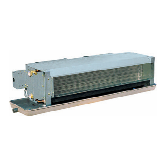
- Page 1 CMCW - 2004 Ceiling Concealed Chilled Water Fan Coil Unit Models: MCW 200 C / MCW 200 H MCW 300 C / MCW 300 H MCW 400 C / MCW 400 H MCW 600 C / MCW 600 H MCW 800 C / MCW 800 H...
-
Page 2: Table Of Contents
"McQuay" is a registered trademark of McQuay International. All rights reserved throughout the world. 2003 McQuay International "Bulletin illustrations cover the general appearance of McQuay International products at the time of publication and we reserve the right to make changes in design and construction at any time without notice."... -
Page 3: General Information
General Information This manual has been prepared as guidance for installing and maintaining the McQuay fan coil unit. McQuay has produced a quality product that will effectively meet your application. However, proper installation and maintenance procedures must be followed to realize the full capability and life of the unit. -
Page 4: Part Descriptions
Part Description Top Panel High Efficiency Coil Fibre Glass Insulation Water Connection Terminal Box Condensate Drain Pan Centrifugal Fan Motor Drain Guide Page 3... -
Page 5: Features
A boundary layer film of air adhering to the fin surface will insulate the fin surface and severely reduces the heat exchange efficiency. MCQUAY slit fin design eliminates this boundary layer of air and creates continuous turbulence for best heat exchange efficiency. - Page 6 Caution 1. The temperature of the surface of PTC heater may be over 200°C if the power of unit is on but the fan of the unit is not running. Don’t touch the unit at this time! 2. The starting current of the unit is more than its working current. It should be considered both the working current and starting current while choosing the fuse.
-
Page 7: Specifications
Specifications 2 Pipes System Specification ( 220V ~ 240 V- 50 Hz) Model MCW200C MCW300C MCW400C MCW600C MCW800C MCW1000C MCW1200C High 1060 1450 1640 2070 Air flow Medium 1180 1360 1760 1100 1510 1500 2300 2850 4400 5410 6240 8010 Total Btu/h 5110... - Page 8 2 Pipes System Specification ( 115 V- 60 Hz) Model MCW200C MCW300C MCW400C MCW600C MCW800C MCW1000C MCW1200C High 1138 1427 1699 2175 Air flow Medium 1155 1308 1750 1054 1444 1500 2300 2850 4400 5410 6240 8010 Total Btu/h 5110 7840 9720 15010...
- Page 9 2 Pipes System Specification ( 208V ~ 230 V- 60 Hz) Model MCW200C MCW300C MCW400C MCW600C MCW800C MCW1000C MCW1200C High 1138 1427 1699 2175 Air flow Medium 1155 1308 1750 1054 1444 2240 3300 4450 6220 7900 9120 10810 Total Btu/h 7640 11260...
- Page 10 4 Pipes System Specification (220V ~ 240V – 50 Hz) Model MCW200H MCW300H MCW400H MCW600H MCW800H MCW1000H MCW1200H High 1138 1427 1699 2175 Air flow Medium 1104 1240 1495 1869 1037 1087 1529 2260 3360 4240 6520 8170 9190 11910 Total Btu/h 7710...
- Page 11 4 Pipes System Specification(115v – 60Hz) Model MCW200H MCW300H MCW400H MCW600H MCW800H MCW1000H MCW1200H High 1138 1427 1699 2175 Air flow Medium 1104 1240 1495 1869 1037 1087 1529 2260 3360 4240 6520 8170 9190 11910 Total Btu/h 7710 11460 14460 22240 27870...
- Page 12 Page 11...
- Page 13 Page 12...
- Page 14 Page 13...
- Page 15 Page 14...
- Page 16 Page 15...
- Page 17 Page 16...
- Page 18 Page 17...
- Page 19 HEATING CAPACITY 2 Pipes System Fan Speed : High (3 Rows Coil) Unit: Btu/h (1Btu = 0.2928104W) Water Entering Air Temperature 69.8ºF (21ºC)(DB) W.P.D Flow Unit Size Entering Water TemperatureºF ºC 104(40) 113(45) 122(50) 131(55) 140(60) 149(65) 158(70) 167(75) 176(80) l/min 6020 7530...
- Page 20 HEATING CAPACITY 4 Pipes System Fan Speed : High (1 Row Coil) Unit: Btu/h (1Btu = 0.2928104W) Water Entering Air Temperature 69.8ºF (21ºC)(DB) W.P.D Flow Unit Size Entering Water TemperatureºF ºC l/min 104(40) 113(45) 122(50) 131(55) 140(60) 149(65) 158(70) 167(75) 176(80) 185(85) 2350 2970...
-
Page 21: Sound Pressure Level
Sound Pressure Level(Measured in anechoic room) Ceiling Concealed Chilled Water Fan Coil Unit 240V/50Hz/1PH - ESP 30Pa 1/1 Octave Sound pressure level (dBA, ref 20µPa) Overall Model Speed A(dBA) 125Hz 250Hz 500Hz 1kHz 2kHz 4kHz 8kHz High 18.5 20.7 20.8 21.1 16.3 32.6... - Page 22 240V/50Hz/1PH - ESP 80Pa 1/1 Octave Sound pressure level (dBA, ref 20µPa) Overall Model Speed A(dBA) 125Hz 250Hz 500Hz 1kHz 2kHz 4kHz 8kHz High 26.8 30.1 37.1 43.2 41.6 24.1 18.1 51.6 MCW400C Medium 23.1 28.5 35.9 42.0 40.8 23.6 17.8 49.6 22.7...
- Page 23 240V/50Hz/1PH - ESP 30Pa 1/1 Octave Sound pressure level (dBA, ref 20µPa) Overall Model Speed A(dBA) 125Hz 250Hz 500Hz 1kHz 2kHz 4kHz 8kHz High 29.4 34.5 38.6 44.1 38.8 25.4 18.1 51.7 MCW1000C Medium 26.1 31.2 35.1 40.4 34.6 20.7 11.6 48.3 22.1...
-
Page 24: Performance Table
Performance Table AIR FLOW VS ESP CURVE 1 - 0Pa 2 - 30Pa 3 - 60Pa 4 - 80Pa MCW200C MCW300C ESP, Pa ESP, Pa MCW400C MCW600C 1000 1800 1600 1400 1200 1000 10 20 30 40 50 60 70 80 90 10 20 30 40 50 60 70 80 90 ESP, Pa ESP, Pa... - Page 25 Air Flow vs ESP Curve Air Flow Capacity Correction Factors MCW800C 2600 Total Cooling 2400 Capacity Sensible Cooling 2200 Capacity 2000 1800 Heating 1600 Capacity 1400 10 20 30 40 50 60 70 80 90 ESP, Pa Air Flow Ratio Water Pressure Drop Curves 2 Pipes System 3 Rows Coil Unit Water Pressure Drop Curve...
-
Page 26: Outlines And Dimensions
Outlines and Dimensions Number Standard Long Unit size of Fans Drain Drain MCW200C MCW300C MCW400C 1014 1114 MCW600C 1214 1314 1005 MCW800C 1464 1564 1198 1237 1255 MCW1000C 1564 1664 1298 1337 1355 MCW1200C 1824 1924 1558 1597 1615 W ATER O U TLET CAUTI O N B E CAR EFU L N O T TO DAM AG E THE C O N NEC TO R W I TH TI G HT FO RCE... -
Page 27: Installations
Installation Receiving All units leaving the McQuay plant have been inspected to ensure the shipment of quality products. All reasonable means are utilized to properly packing the fan coil unit. Carefully inspect all shipments immediately upon delivery. When damage is visible, note this fact on the carrier’s freight bill and request that the carrier send a representative to inspect the damage. - Page 28 W A TER O U TLET C AU TI O N BE C AR EF UL N OT TO D AM AG E TH E C O N N EC TO R W ITH TI G H T FO R C E W HEN PI PI N G .
- Page 29 Pipe connection Chilled water pipe connection Connect size Rc3/4 chilled water pipes to the unit. Water inlet is on the bottom and water outlet is on top. Drain pipe connection Drain pipe can be either PVC or steel. Connect R3/4 connector to drain pipe of the unit. The connection must be concealed with rubberized fabric to avoid water leak.
-
Page 30: Wiring Diagrams
Wiring Diagrams Electrical Wiring Diagram Electrical wiring connection must be done according to the wiring diagram on the unit. Refer to Figure 7 to Figure 18. The unit must be GROUNDED to the earth system of the building. All field wiring must be installed in accordance with the national wiring regulation and Fire Department regulation. - Page 31 For Models: MCW800C MCW1000C MCW1200C (0Pa and 30Pa) Figure 8 Figure 8 For Models: MCW200C MCW300C MCW400C MCW600C (60Pa and 80Pa) 60Pa: LF--Low Speed MF--Medium Speed HF--High Speed 80Pa: MF--Low Speed HF--Medium Speed SHF--High Speed Figure 9 Figure 9 Page 30...
- Page 32 For Models: MCW800C MCW1000C MCW1200C (60Pa and 80Pa) Figure 10 For Models : MCW200CD MCW300CD MCW400CD (0Pa and 30Pa) Figure 11 Figure 11 Page 31...
- Page 33 For Models : MCW200CD MCW300CD MCW400CD (0Pa and 30Pa) Figure 12 Figure 12 For Models : MCW600CD (0Pa and 30Pa) Figure 13 Figure 13 Page 32...
- Page 34 For Models : MCW800CD MCW1000CD MCW1200CD (0Pa and 30Pa) Figure 14 Figure 14 For Models : MCW200CD MCW300CD MCW400CD (60Pa and 80Pa) 60Pa: LF--Low S Figure 15 Page 33...
- Page 35 For Models : MCW200CD MCW300CD MCW400CD (60Pa and 80Pa) Figure 16 For Models : MCW600CD (60Pa) Figure 17 Page 34...
- Page 36 For Models : MCW800CD MCW1000CD MCW1200CD (60Pa and 80Pa) Figure 18 WARNING: Switch shall be connected to the supply terminals and shall have a contact separation of at least 3 mm in each pole. Confirm that the unit has been switched OFF before installing or servicing the unit. Page 35...
-
Page 37: Optional Parts
OPTIONAL PARTS Electric valve package kits The electric valve package kits are furnished completely soldered and leak tested at the factory. Four(4) solder connections are required to complete the installation of the valve package into the system (two at the coil supply and return connections and two at the supply and return run outs). - Page 38 Valve Actuator installation Latch the manual operating lever in the engaged position (N.C. only). Depress the release button (See Figure 19). Align the body with the actuator to ensure the stem is inserted into the large mating hole on the bottom side of the actuator. Engage the actuator on the body and release the button.
- Page 39 Ventilation When the ventilation function is selected (RAB10.1), the heating and cooling contacts are always open and the fan operates at the selected speed. Changeover Heating or cooling is selected with a switch located on the front of the thermostat. Adjustments The required temperature can be selected by a set point adjuster on the front of the thermostat.
-
Page 40: Connection Diagram
Connection diagram Operating voltage AC 250 V 3-speed fan Neutral Control output “Fan speed ”, AC 250 V Control output “Fan speed ”, AC 250 V Control output “Fan speed ”, AC 250 V Control output “Valve actuator”, AC 250 V Thermal valve or zone valve Figure 21 The electric valve package kits and room thermostat are optional parts. - Page 41 REGISTERED S&E ISO 9002 ©2003 McQuay International +1 (800) 432-1342 www.mcquay.com...
Need help?
Do you have a question about the MCW 200 C and is the answer not in the manual?
Questions and answers