Table of Contents
Advertisement
Advertisement
Table of Contents

Subscribe to Our Youtube Channel
Related Manuals for McQuay RoofPak RDS 800C


Summary of Contents for McQuay RoofPak RDS 800C
- Page 1 Artisan Technology Group is your source for quality new and certified-used/pre-owned equipment SERVICE CENTER REPAIRS WE BUY USED EQUIPMENT • FAST SHIPPING AND DELIVERY Experienced engineers and technicians on staff Sell your excess, underutilized, and idle used equipment at our full-service, in-house repair center We also offer credit for buy-backs and trade-ins •...
- Page 2 IM 178-6 Group: Applied Systems Part Number: 347673Y-01 Date: January 1997 ® RoofPak Applied Rooftop Systems Air Handler RDS 800C & 802C ® ® ® ©1997 McQuay International Artisan Technology Group - Quality Instrumentation ... Guaranteed | (888) 88-SOURCE | www.artisantg.com...
-
Page 3: Table Of Contents
Table of Contents Introduction ........3 Typical Compressor Staging Outputs . -
Page 4: Introduction
This manual provides general information about the “C” information on using and programming the MicroTech unit vintage McQuay RoofPak applied rooftop unit, Model RDS. controller, refer to the appropriate operation manual (see In addition to an overall description of the unit, it includes Table 1). -
Page 5: Unit Description
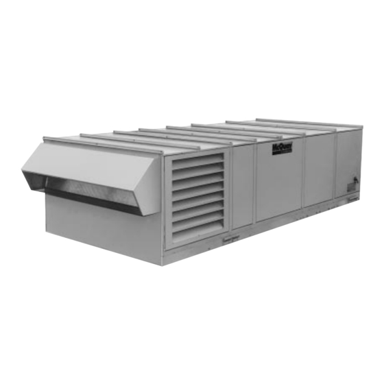
Unit Description Typical Component Locations These figures are for reference only. See the certified submit- Figure 1 shows a typical RDS unit with the location of the major components and also lists some major dimensions. tals for actual specific dimensions. Figure 1. -
Page 6: Control Locations
Control Locations Figure 2 shows the locations of the various control compo- “Controls, Settings, and Functions,” and the wiring diagram nents mounted throughout the unit. See “Control Panel legend which is included in the “Wiring Diagrams” section of Locations” for the locations of control components mounted this manual. -
Page 7: Control Panel Locations
Control Panel Locations The unit control panels and their locations are shown in the ration. Specific unit configurations may differ slightly from these figures depending on the particular unit options. following figures. These figures show a typical unit configu- Electric Heat Control Panel (Optional) Main Control Panel Main control panel... - Page 8 Electric heat control panel HL14 IM 178 / Page 7 Artisan Technology Group - Quality Instrumentation ... Guaranteed | (888) 88-SOURCE | www.artisantg.com...
-
Page 9: Controls, Settings, And Functions
Page 8 / IM 178 Artisan Technology Group - Quality Instrumentation ... Guaranteed | (888) 88-SOURCE | www.artisantg.com... - Page 10 IM 178 / Page 9 Artisan Technology Group - Quality Instrumentation ... Guaranteed | (888) 88-SOURCE | www.artisantg.com...
-
Page 11: Mechanical Installation
Mechanical Installation The installation of this equipment shall be in accordance with CAUTION the regulations of authorities having jurisdiction and all applicable codes. It is the responsibility of the installer to determine and follow the applicable codes. Sharp edges are inherent to sheet metal parts, screws, clips, and similar items. -
Page 12: Roof Curb Assembly And Installation
Ventilation clearance Do not locate outside air intakes near exhaust vents or Following are minimum ventilation clearance recommenda- other sources of contaminated air. tions. The system designer must consider each application If the unit is installed where windy conditions are com- and assure adequate ventilation. - Page 13 Figure 5a. RDS roof curb assembly instructions “X” “Y” “XX” “YY” RETURN NONE 24.0 82.0 2083 (173) (2) 15" FC 24.0 82.0 2083 (38) 30" AF 30.0 76.0 1930 (508) 76 (1930) 40" AF 36.0 78.0 1981 14.8 Inside Inside Supply (191) (51)
-
Page 14: Post And Rail Mounting
Post and Rail Mounting Figure 6. Post and rail mounting When mounting by post and rail, the structural support should be run the full length of the unit. The structural 94" member should be located at the base of the unit as shown (2388 mm) *5"... - Page 15 Lifting points To determine the required lifting cable lengths and whether Table 3. “X” dimension (see Figure 8) four- or six-point lifting is required, use Tables 3 and 4 below and Figure 8. OUTDOOR/RETURN AIR 800C 802C SECTION Referring to Figure 8, note that dimension A is the dis- 100 O.A.
-
Page 16: Installing Ductwork
For bottom discharge and return units not provided with a Where return air ducts are not required, it is recommended McQuay roof curb, the installing contractor should make an that a sound absorbing T or L section be connected to the... -
Page 17: Installing Building Static Pressure Sensor Taps
back wall of the discharge plenum. Sensing tubes should and that tubing is protected by rubber grommets. Care- enter the unit discharge plenum through the main supply fully connect the HI and LO tubes to the appropriate duct trunk. Make sure that duct penetrations are sealed sensor fittings. -
Page 18: Condensate Drain Connection
Condensate Drain Connection The unit is provided with a 1.5" male NPT condensate drain requirements. Sealed drain lines require venting to assure connection. Refer to certified drawings for the exact location. proper condensate flow. The unit and drain pan must be level side to side and a P-trap Where the cooling coils have intermediate condensate must be installed for proper drainage. - Page 19 Piping recommendations pair, the system should be evacuated as described in the following paragraphs. 1. Use type K or L clean copper tubing. All joints should be thoroughly cleaned or brazed with high temperature solder. WARNING 2. Piping sizes should be based on temperature/pressure limitations as recommended in the following paragraphs.
-
Page 20: Unit Piping
Charging the system Note: It is recommended that the total operating charge per circuit be stamped on the unit nameplate for future reference. 1. After all refrigerant piping is complete and the system has been evacuated, it can be charged as described in the Refrigerant charge paragraphs following. - Page 21 Bypass used. Some products will have higher freezing points in their natural state than when mixed with water. The freezing of coils is not the responsibility of McQuay International. Refer to “Winterizing Coils” in the “Main- Supply tenance” section of this manual.
-
Page 22: Vestibule Assembly Instructions
2. Do not reduce pipe size at the coil return connection. 1. 5 psi (34.5 kPa) steam must be supplied to coils at all Carry return connection size through the dirt pocket, times. making the reduction at the branch leading to the trap. 2. - Page 23 Step 2 Step 4 Remove gasketing around door flange and save for use on 1. Reassemble access door to vestibule by screwing hinges vestibule. See Step 4. Remove door and save for Step 4. into side panel using screws saved from Step 1. (Access door must be attached to the vestibule in the same Figure 16b.
-
Page 24: Damper Assemblies
Damper Assemblies The optional damper assemblies described in this section The outside air return air damper assembly (economizer) are provided with manually adjustable linkages, or may be comes with manually adjustable linkage. This adjustable shipped with factory installed actuators and linkages. linkage can also be used for connection of a damper operator. - Page 25 Intake hood damper (0 to 100% outside air) Units requiring 100% outside air are provided with a rain hood dampers fully during unit operation and closing the dampers and dampers which may be controlled by a single actuator. during the off cycle. No unit mounted exhaust dampers are The actuator provides two-position control for opening the provided.
-
Page 26: Cabinet Weatherproofing
Face and bypass dampers Face and bypass dampers are available for use with contrac- through a jack shaft for connection to a factory or field in– tor heating an cooling coils. The damper sets are linked stalled actuator. Figure 20. Optional Contractor Coil... -
Page 27: Electrical Installation
Electrical Installation Field Power Wiring Wiring must comply with all applicable codes and ordi- WARNING nances. The warranty is voided if wiring is not in accordance with these specifications. An open fuse indicates a short, ground, or overload. Before replacing a fuse or restarting a Hazardous voltage. - Page 28 With optional electrical power package WARNING RDS units are provided with internal power wiring for single point power connection. The single power block or an op- Improper line voltage or excessive phase imbalance tional disconnect switch is located within the main control constitutes product abuse.
-
Page 29: Field Control Wiring
Field Control Wiring RoofPak applied rooftop units are available with several Figure 23. Field control wiring connections control arrangements which may require low voltage field wiring. Detailed descriptions of various field control wiring options and requirements are included in the “Field Wiring” section of Bulletin No. -
Page 30: Preparing Unit For Operation
Preparing Unit for Operation WARNING Moving machinery hazard. May cause severe injury or death. Disconnect power and lock off before servicing equipment. More than one disconnect may be required to de-energize unit. Relief Damper Tie-Down Economizer sections with a 30" or 40" return fan have a relief movement of dampers. -
Page 31: Adjustment Of Scroll Dampers
Adjustment of Scroll Dampers Two sets of scroll dampers are provided in the housing of the Figure 26. Scroll damper adjustment twin 15" x 6" supply fan to allow control of air volume to each Adjustment Assembly fan wheel. At the factory, these dampers are fully closed unrestricting airflow. -
Page 32: Adjustment Of Seismic Restraints
Adjustment of Seismic Restraints Spring mounted supply air and return air fans may be ordered When a seismic restraint is properly adjusted and the fan with factory installed seismic restraints. The system consists is operating normally, the neoprene center bumper will be of four snubbers, one located next to each spring isolator. -
Page 33: Sequences Of Operation
Sequences of Operation The following sequences of operation are for a typical “C” from those described here. Refer to the wiring diagrams vintage applied rooftop unit that is equipped with an econo- supplied with the unit for exact information. mizer, a return air fan, a MicroTech controller, an external For a detailed description of operation information relat- ing to the MicroTech controller’s software, refer to the time clock, and a Remote Monitor Panel. -
Page 34: Cooling Operation
Cooling Operation Chilled water coil, modulating valve Refer to the “Typical Actuator Control Circuit ” schematic in energized, output relay OBA2 opens the chilled water valve the following section, “Wiring Diagrams,” as you read this (line 332). When terminals 4 and 2 are energized, output relay sequence of operation. -
Page 35: Wiring Diagrams
Wiring Diagrams Wiring Diagrams Legend Designation Description Std. Location Designation Description Std. Location ACT1 ....Actuator Motor, Supply Fan Vanes ......Supply Air Sect. OAE ....Outside Air Enthalpy Control ........Economizer Sect. ACT2 ....Actuator Motor, Return Fan Vanes ......Return Air Sect. OAT .... -
Page 36: Typical Power Circuits With Controls
Typical Power Circuit Typical Compressor Staging Outputs IM 178 / Page 35 Artisan Technology Group - Quality Instrumentation ... Guaranteed | (888) 88-SOURCE | www.artisantg.com... -
Page 37: Typical Main Control Circuit (Vav Units)
Typical Main Control Circuit (VAV Units) Page 36 / IM 178 Artisan Technology Group - Quality Instrumentation ... Guaranteed | (888) 88-SOURCE | www.artisantg.com... -
Page 38: Typical Main Control Circuit (Cav-Ztc Units)
Typical Main Control Circuit (CAV-ZTC Units) IM 178 / Page 37 Artisan Technology Group - Quality Instrumentation ... Guaranteed | (888) 88-SOURCE | www.artisantg.com... -
Page 39: Typical Main Control Circuit (Cav-Dtc Units)
Typical Main Control Circuit (CAV-DTC Units) Page 38 / IM 178 Artisan Technology Group - Quality Instrumentation ... Guaranteed | (888) 88-SOURCE | www.artisantg.com... -
Page 40: Typical Actuator Control Circuit
Typical Actuator Control Circuit Typical Supply/Return Fan Control Circuit IM 178 / Page 39 Artisan Technology Group - Quality Instrumentation ... Guaranteed | (888) 88-SOURCE | www.artisantg.com... -
Page 41: Typical Gas Furnace Control Circuit
Typical Gas Furnace Control Circuit (Modulating Burner, Mixed Air Intake) Sequence of Operation: When the rooftop unit is energized, 120 volt power is supplied through the system on-off switch S1 to OBA3 contacts. Upon a call for heat, the control system will close OBA3, thus energizing relay R20. 120 Volt power is furnished through the system on-off switch S1, through relay R20 closed contacts, through the burner on-off switch S3, through the high limit control FLC and through the optional automatic reset low pressure switch LP5 and the optional manual reset high gas pressure switch HP5, to power terminal 6 on the flame safeguard control FSG. -
Page 42: Typical Electric Heat Control Circuit (Multistage)
Typical Electric Heat Control Circuit (Multistage) IM 178 / Page 41 Artisan Technology Group - Quality Instrumentation ... Guaranteed | (888) 88-SOURCE | www.artisantg.com... -
Page 43: Unit Options
Unit Options Enthalpy Control Outside air enthalpy control (OAE) Figure 29. Enthalpy control settings (32) (35) (38) (40.5) (29.5) Units with MicroTech control and an economizer come standard with an electromechanical enthalpy control device (OAE) which senses both the humidity and temperature of the outside air entering the unit. -
Page 44: External Time Clock
External Time Clock An external time clock can be used as an alternative to (or in followed. When the circuit is closed, power is fed to DH1-1. addition to) the MicroTech controller’s internal scheduling The MicroTech controller responds by placing the unit in the function. -
Page 45: Variable Inlet Vanes
Variable Inlet Vanes Variable inlet vanes are installed on the supply and return On units with vane controls on both the supply and return fans of VAV units. They are also installed on the return fans fan, it is important that both actuators have exactly 180- of constant volume units that have direct building static degree rotation to assure proper “tracking”... - Page 46 Figure 31. Supply fan vane assembly Open 180° To Open Closed 24° X = 3.00" — 20" Wheel (800C) 2.80" — 24" Wheel (802C) Adjustable [11/8" (28 mm) slot] Floating Link Figure 32. Return fan vane assembly View #1 Closed Open 30"...
-
Page 47: Check, Test And Start Procedures
Disconnect electrical power before servicing this equipment. All units are completely run tested at the factory to assure completed, signed, and returned to McQuay International. proper operation in the field. Nevertheless, the following A representative of the owner or the operator of the... -
Page 48: Economizer Start-Up
3. If the fans are equipped with optional spring isolators, fan drives are usually shipped with fixed pitch sheaves that check the fan spring mount adjustment. When the fans will provide the selected fan speed; however, the supply fan are running they should be level. Refer to “Spring Isolated drives are usually shipped with variable pitch sheaves that Fans”... -
Page 49: Air Balancing
Air Balancing Air balancing should be performed by a qualified air balanc- Figure 33. VM and VP variable pitch sheaves ing technician. Note that the supply fan motors are usually shipped with variable pitch sheaves which are typically set at the low end of the drive’s fan rpm range. - Page 50 Figure 34. LVP variable pitch sheaves Section A-A Section A-A 9. Be sure that all keys are in place and that all setscrews and ⁄ ⁄ turn until the inner and outer ring screw holes are all capscrews are tight before starting the drive. Check lined up.
-
Page 51: Final Control Settings
Final Control Settings When all start-up procedures have been completed, set the 11. Set the dirty filter set points as required (keypad menu controls and program the MicroTech controller for normal 22). If a Remote Monitor Panel is being used, set the set operation. - Page 52 Control parameter record (cont’d) FINAL MENU MENU NAME MENU ITEM = SETTING Set Point = ____ °F Clg Control (VAV & CAV-DTC) ___________ Min OAT = ____ °F ___________ Min Spt = ____ °F Programs: ART1, ART2, ART3, ___________ Max Spt = ____ °F ART4, ART6 and ART8 ___________ Reset = No Reset...
- Page 53 Control parameter record (cont’d) FINAL MENU MENU NAME MENU ITEM = SETTING Duct Pressure (VAV) Duct Spt = ____ "WC ___________ Max Spt = ____ "WC ___________ Programs: ART1, ART2, ART3 Reset = No Reset ___________ and ART4 Network Position Deadband = ____ "WC ___________ Mod Lim = ____ "WC...
- Page 54 Control parameter record (cont’d) FINAL MENU MENU NAME MENU ITEM = SETTING Outdr Damper (CAV) Min Airflow = ____ % ___________ Min Type = None ___________ Programs: ART5, ART6, ART7 External and ART8 ____ % @ 5V Ext ___________ Enthalpy = Yes ___________ Changeover = ____ °F ___________...
- Page 55 Control parameter record (cont’d) FINAL MENU MENU NAME MENU ITEM = SETTING Optimal Start Opt Start = ___________ Auto Update =Yes ___________ Ht Rate = ____ °F/Min ___________ Heat OAT = ____ °F ___________ Ht Factor = ____ Min ___________ Cl Rate = ____ °F/Min ___________ Cool OAT = ____ °F...
-
Page 56: Maintenance
Maintenance Installation and maintenance are to be performed only by qualified personnel who are experienced with this type of equipment and familiar with local codes and regulations. CAUTION WARNING Moving machinery and electrical power hazards. May Sharp edges are inherent to sheet metal parts, screws, cause severe personal injury or death. -
Page 57: Setscrews
3. Run the motor for five minutes before replacing the plugs. Table 14. Recommended greases Note: Specific greasing instructions may be found on a PRODUCT TEMP. MANUFACTURER ° tag attached to the motor. If special lubrication instructions NAME RANGE ( are on the motor, they will supersede all other instructions. -
Page 58: Supply Fan Wheel-To-Funnel Alignment
Supply Fan Wheel-to-Funnel Alignment If the unit is equipped with an airfoil or backward curved supply 3. Retighten the setscrews to the torque specification given fan, the fan wheel-to-funnel alignment must be as shown in in Table 16. Tighten the setscrews over the keyway first; Figure 37 or 38 to obtain proper air delivery and operating tighten those at 90 degrees to the keyway last. -
Page 59: Service And Warranty Procedure
Replacement Parts When writing to McQuay for service or replacement parts, to provide the number on the specific diagram. If replacment provide the model number, serial number, and G.O. number parts are required, include the date of unit installation, the of the unit as stamped on the serial plate attached to the unit. -
Page 60: Product Warranty
To obtain infor- be the date of start-up and the warranty shall expire twelve mation or to gain factory help, contact McQuay International, (12) months from that date. Warranty Department, P.O. Box 1551, Minneapolis, MN No person (including any agent, salesman, dealer or 55440, telephone (612) 553-5330. - Page 61 13600 Industrial Park Boulevard, P.O. Box 1551, Minneapolis, MN 55440 USA (612) 553-5330 Printed on recycled paper containing at least 10% post-consumer recycled material. Artisan Technology Group - Quality Instrumentation ... Guaranteed | (888) 88-SOURCE | www.artisantg.com...
- Page 62 Artisan Technology Group is your source for quality new and certified-used/pre-owned equipment SERVICE CENTER REPAIRS WE BUY USED EQUIPMENT • FAST SHIPPING AND DELIVERY Experienced engineers and technicians on staff Sell your excess, underutilized, and idle used equipment at our full-service, in-house repair center We also offer credit for buy-backs and trade-ins •...
Need help?
Do you have a question about the RoofPak RDS 800C and is the answer not in the manual?
Questions and answers
what is the cfm of a McQuay RHS800BA package unit