Pioneer DV-626D Service Manual
Hide thumbs
Also See for DV-626D:
- Operating instructions manual (72 pages) ,
- Operating instructions manual (132 pages)
Table of Contents
Advertisement
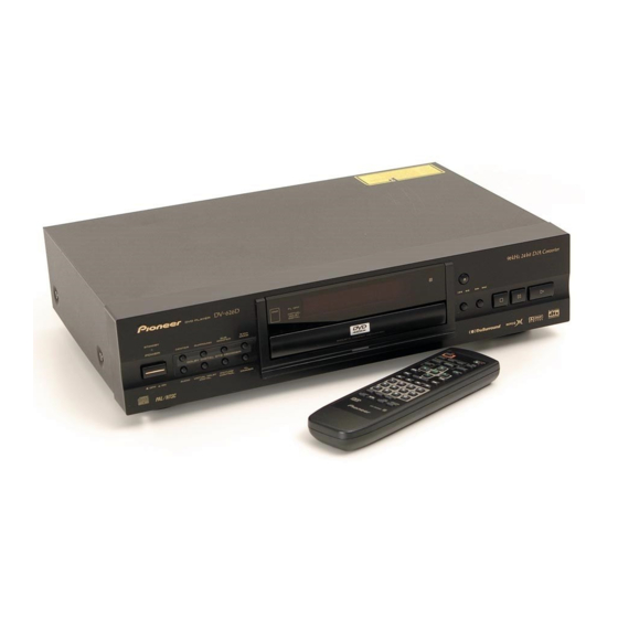
DVD PLAYER
DV-626D
THIS MANUAL IS APPLICABLE TO THE FOLLOWING MODEL(S) AND TYPE(S).
Model
Type
DV-626D
KU
KC
WY
WV
CONTENTS
1. SAFETY INFORMATION ....................................... 2
2. EXPLODED VIEWS AND PARTS LIST ................. 4
4. PCB CONNECTION DIAGRAM ........................... 37
5. PCB PARTS LIST ................................................ 52
6. ADJUSTMENT ..................................................... 59
PIONEER CORPORATION
PIONEER ELECTRONICS SERVICE, INC. P.O. Box 1760, Long Beach, CA 90801-1760, U.S.A.
PIONEER ELECTRONIC (EUROPE) N.V. Haven 1087, Keetberglaan 1, 9120 Melsele, Belgium
PIONEER ELECTRONICS ASIACENTRE PTE. LTD. 253 Alexandra Road, #04-01, Singapore 159936
c
PIONEER CORPORATION 1999
ST ANDBY / ON
Power Requirement
AC120V
AC120V
AC220 - 240V
AC220 - 240V
4-1, Meguro 1-chome, Meguro-ku, Tokyo 153-8654, Japan
ÛN¿><>Û
D VD PLA YER
DNR
FL OFF
0
VIRTUAL
Î
DOLBY
DIGIT AL
SUB
5.1CH
4
1
¡
¢
CENTER
SURROUND
WOOFER
MODE
7
DOLBY DIGIT AL DTS DECODER
ACOUSTIC DAMPER MECHANISM
AUDIO
VIRTUAL DOLBY
PICTURE
FL
DIGIT AL
CONTROL
DIMMER
Region No.
1
1
2
2
7. GENERAL INFORMATION .................................. 61
7.1 DIAGNOSIS ................................................... 61
7.1.1 TEST MODE SCREEN DISPLAY ............. 61
7.1.2 TROUBLE SHOOTING ............................ 63
7.1.3 ERROR CODE ......................................... 64
7.1.4 DISASSEMBLY ........................................ 68
7.2 PARTS ........................................................... 69
7.2.1 IC ............................................................. 69
7.2.2 DISPLAY .................................................. 86
8. PANEL FACILITIES AND SPECIFICATIONS ....... 87
ORDER NO.
8
3
RRV2191
Remarks
T - IZE AUG. 1999 Printed in Japan
Advertisement
Table of Contents

Related Manuals for Pioneer DV-626D


Summary of Contents for Pioneer DV-626D
-
Page 1: Table Of Contents
PIONEER CORPORATION 4-1, Meguro 1-chome, Meguro-ku, Tokyo 153-8654, Japan PIONEER ELECTRONICS SERVICE, INC. P.O. Box 1760, Long Beach, CA 90801-1760, U.S.A. PIONEER ELECTRONIC (EUROPE) N.V. Haven 1087, Keetberglaan 1, 9120 Melsele, Belgium PIONEER ELECTRONICS ASIACENTRE PTE. LTD. 253 Alexandra Road, #04-01, Singapore 159936 PIONEER CORPORATION 1999 T –... -
Page 2: Safety Information
The use of a substitute replacement component which does Leakage 0.5mA current Device not have the same safety characteristics as the PIONEER tester under recommended replacement one, shown in the parts list in test this Service Manual, may create shock, fire, or other hazards. - Page 3 DV-626D IMPORTANT THIS PIONEER APPARATUS CONTAINS LASER OF CLASS 1. SERVICING OPERATION OF THE APPARATUS SHOULD BE DONE BY A SPECIALLY INSTRUCTED PERSON. LASER DIODE CHARACTERISTICS FOR DVD : MAXIMUM OUTPUT POWER : 5 mW WAVELENGTH : 655 nm FOR CD :...
-
Page 4: Exploded Views And Parts List
DV-626D 2. EXPLODED VIEWS AND PARTS LIST • NOTES: Parts marked by "NSP" are generally unavailable because they are not in our Master Spare Parts List. • mark found on some component parts indicates the importance of the safety factor of the part. - Page 5 Operating Instructions (French) See Contrast table (2) Label VRW1629 Operating Instructions See Contrast table (2) (English/French) (2) CONTRAST TABLE DV-626D/KU, KC, WY and WV are constructed the same except for the following : Part No. Mark No. Symbol and Description Remarks KU Type KC Type...
-
Page 6: Exterior Section
VNK4509 Screw VBA1057 Screw IBZ30P080FMC Door Spring VBH1305 (2) CONTRAST TABLE DV-626D/KU, KC, WY and WV are constructed the same except for the following : Part No. Mark No. Symbol and Description Remarks KU Type KC Type WY Type WV Type... -
Page 7: Front Panel Section
PW Button (POWER) See Contrast table (2) Main Key VNK4447 Screw BBZ30P080FMC (2) CONTRAST TABLE DV-626D/KU, KC, WY and WV are constructed the same except for the following : Part No. Mark No. Symbol and Description Remarks KU Type KC Type... - Page 8 DV-626D 2.4 BOTTOM VIEW SECTION Refer to "2.5 LOADING MECHANISM ASSY". WY and WV Types Only WY and WV Types Only PICKUP Assy WY and WV Types Only WY and WV Types Only...
- Page 9 Flexible Cable (07P) See Contrast table (2) (SCRB CN2 ↔ DVDM CN904) • • • • • (2) CONTRAST TABLE DV-626D/KU, KC, WY and WV are constructed the same except for the following : Part No. Mark No. Symbol and Description Remarks...
- Page 10 DV-626D 2.5 LOADING MECHANISM ASSY • Top View • Bottom View Refer to "2.6 TRAVERSE MECHANISM ASSY-S". LOADING MECHANISM ASSY PARTS LIST Mark No. Description Part No. Mark No. Description Part No. Traverse Mechanism Assy-S VXX2653 Loading Motor Assy VXX2505...
- Page 11 DV-626D 2.6 TRAVERSE MECHANISM ASSY-S • Top View TRAVERSE MECHANISM ASSY-S PARTS LIST Mark No. Description Part No. Mark No. Description Part No. SMEB Assy VWG2048 Hook VNL1770 FGSB Assy VWG2009 FFC Holder VNL1802 Motor VXM1079 Mechanism Base VNL1806 Motor...
-
Page 12: Block Diagram And Schematic Diagram
DV-626D 3. BLOCK DIAGRAM AND SCHEMATIC DIAGRAM 3.1 BLOCK DIAGRAM 36/16M DVDM ASSY (24P) (24P) YCBR0-7 CN120 SPDL (Y0-Y7) 95-98, MOTOR OEIC MPEG2 100-103 RF IC SD0-SD7 DSPRF 149,150, DECODER 7,6, 7,6, B1-B4 57-60 IC101 152-155, DECODER DOUT0 MITUBISHI 63-66... - Page 13 DV-626D (26P) (26P) WY,WV POWER CN110 CN201 CN102 TYPES S1000 ONLY M + 6V +12V POWER MSWB ASSY +12V SUPPLY ASSY CN101 LIVE AC IN +3.3V NEUTRAL WY,WV TYPES ONLY EV+5V – 27V SCRB ASSY AV OUT (V,Y) (7P) TK15402M...
- Page 14 DV-626D 3.2 LOMB, LOSB, SMEB, FGSB ASSYS and OVERALL WIRING DIAGRAM Note : When ordering service parts, be sure to refer to "EXPLODED VIEWS and PARTS LIST" or "PCB PARTS LIST". WY, WV TYPES ONLY SCRB ASSY (VWV1721) WY, WV...
-
Page 15: Dvdm Assy
DV-626D WY, WV TYPES ONLY MSWB ASSY (VWG2073) 1/4- POWER SUPPLY ASSY AC POWER CORD (KU, KC : VWR1316) KU, KC : ADG7021 DVDM ASSY WY : ADG1127 WV : ADG7004 (WY, WV : VWR1314) (KU, KC: VWS1384) KU, KC... - Page 16 DV-626D 3.3 DVDM ASSY (1/4) DVDM ASSY (KU, KC : VWS1384) , (WY, WV : VWS1393) (DVD) (DVD) CN201 VKN1324 CN110 VKN1479 (CD) (CD) CN120 VKN1484 CN1030 IC352 : VKN1471 SPDL & FTS DRIVER...
- Page 17 DV-626D : The power supply is shown with the marked box. : RF SIGNAL ROUTE : ROM DATA SIGNAL ROUTE : FOCUS SERVO LOOP LINE : TRACKING SERVO LOOP LINE : SLIDER SERVO LOOP LINE (DVD) (DVD) − − KU,KC −...
- Page 18 DV-626D 3.4 DVDM ASSY (2/4) DVDM ASSY (KU, KC : VWS1384) 3 TO 5 CONVERTER (WY, WV : VWS1393) MC74VHCT541ADT 5 TO 3 CONVERTER MC74VHCT541DT (V_SEL) X601 20MHz DSS1110...
- Page 19 DV-626D : The power supply is shown with the marked box. : AUDIO SIGNAL ROUTE : ROM DATA SIGNAL ROUTE MN414800CSJ-07 DVD ENCODER...
- Page 20 DV-626D 3.5 DVDM ASSY (3/4) DVDM ASSY (KU, KC : VWS1384) , (WY, WV : VWS1393) KU, KC ONLY 100/10 MPEG2 DECODER MITSUBISHI AV1 3 - 5 CONVERTER TC74VHCT541ADT...
- Page 21 DV-626D : AUDIO SIGNAL ROUTE : ROM DATA SIGNAL ROUTE : VIDEO SIGNAL ROUTE : Y SIGNAL ROUTE : C SIGNAL ROUTE : R SIGNAL ROUTE : G SIGNAL ROUTE : B SIGNAL ROUTE CLOCK GENERATOR CN101...
- Page 22 VSX-806RDS 3.6 DVDM ASSY (4/4) DVDM ASSY (KU, KC : VWS1384) , (WY, WV : VWS1393) : AUDIO SIGNAL ROUTE : VIDEO SIGNAL ROUTE : Y SIGNAL ROUTE : C SIGNAL ROUTE : R SIGNAL ROUTE : G SIGNAL ROUTE : B SIGNAL ROUTE VKN1585 3 TO 5 CONVERTER...
- Page 23 DV-626D...
- Page 24 DV-626D 3.7 VQEB ASSY WY, WV ONLY VQEB ASSY (KU, KC : VWV1669) (WY, WV : VWV1711) (6 ch, DNR) VIDEO ENCODER...
- Page 25 DV-626D : The power supply is shown with the marked box. WY, WV ONLY CN802 14 17 12 15 13 16 : ROM DATA SIGNAL ROUTE : R SIGNAL ROUTE : VIDEO SIGNAL ROUTE : G SIGNAL ROUTE : Y SIGNAL ROUTE...
- Page 26 DV-626D 3.8 JCKB ASSY (1/2) JCKB ASSY (KU, KC : VWV1682) , (WY, WV : VWV1681) IC401 : 96k, 24 bit 6 ch DAC DTS DECODER...
- Page 27 DV-626D : AUDIO SIGNAL ROUTE WY, WV ONLY WY, WV ONLY TC4W53F : The power supply is shown with the marked box.
- Page 28 DV-626D 3.9 JCKB ASSY (2/2) JCKB ASSY (KU, KC : VWV1682) (WY, WV : VWV1681) KU, KC ONLY WY, WV ONLY WY, WV ONLY WY, WV ONLY WY, WV ONLY KU, KC ONLY KU, KC ONLY WY, WV ONLY...
- Page 29 DV-626D : The power supply is shown with the marked box. : AUDIO SIGNAL ROUTE : VIDEO SIGNAL ROUTE : Y SIGNAL ROUTE : C SIGNAL ROUTE VIDEO AMP WY, WV ONLY KU, KC ONLY (CB) (CB) (CR) (CR)
- Page 30 DV-626D 3.10 FLKB, PWSB and DILB ASSYS S101-S106: ASG7013 FLKY ASSY R141 R143 (KU, KC : VWG2089) KU,KC 6.2k (WY, WV : VWG2090) WY,WV WY, WV ONLY KU, KC ONLY FL TUBE...
- Page 31 DV-626D : The power supply is shown with the marked box. PWSB ASSY (KU, KC : VWG2094) (WY, WV : VWG2095) WY, WV ONLY WY, WV ONLY KU, KC ONLY S201-S209: ASG7013 DILB ASSY (VWG2099) FLKY ASSY PWSB ASSY S101 : 8 (PAUSE)
-
Page 32: Scrb Assy
DV-626D 3.11 SCRB ASSY SCRB ASSY (VWV1721) (WY, WV ONLY) VKN1243 CN777 VKN1238 CN904... - Page 33 DV-626D : AUDIO SIGNAL ROUTE : The power supply is shown with the marked box. : V/CB SIGNAL ROUTE : Y SIGNAL ROUTE : C SIGNAL ROUTE VKB1127...
- Page 34 DV-626D 3.12 POWER SUPPLY and MSWB ASSYS NOTE OF SPARE PARTS IN POWER SUPPLY (SYPS) ASSY • In case of repairing, use the described parts only to prevent an accident. • Please write the red mark on the board when the primary section of POWER SUPPLY (SYPS) Assy is repaired.
- Page 35 DV-626D • NOTE FOR FUSE REPLACEMENT FOR CONTINUED PROTECTION AGAINST RISK OF FIRE. CAUTION - REPLACE WITH SAME TYPE AND RATINGS ONLY. P211 L211 D211 VEK1041 39µH/1.3A VZF1065 1.0A/60V C212 C211 D213 330/35 100/35 MTZJ15B CN201 L711 D711 R711 52806-2610 39µH/1.3A...
- Page 36 DV-626D WAVEFORMS Note : The encircled numbers denote measuring point in the schematic diagram. Measurement condition : No. 1 to 4 and 6 to 11 : Disc MA1, Title 1-chp 1 No. 5 : CD, ABEX-784 Track 1 No. 12 to 14 : MJK1, Title 1-chp 4 or T2-1 No.
-
Page 37: Pcb Connection Diagram
DV-626D 4. PCB CONNECTION DIAGRAM NOTE FOR PCB DIAGRAMS : 1. Part numbers in PCB diagrams match those in the schematic 3. The parts mounted on this PCB include all necessary parts for diagrams. several destinations. 2. A comparison between the main parts of PCB and schematic For further information for respective destinations, be sure to diagrams is shown below. - Page 38 DV-626D • This PCB is a four-layered board. 4.2 DVDM ASSY CN666 CN999 DVDM ASSY IC23 IC26 IC31 Q810 Q808 Q812 IC25 IC54 Q809 Q807 Q811 IC21 IC801 VR851 IC807 VC21 IC22 IC806 IC903 IC261 IC303 PICKUP ASSY IC302 IC702...
- Page 39 DV-626D • This PCB is a four-layered board. DVDM ASSY IC905 IC803 IC27 IC805 IC802 IC73 CN101 IC201 IC701 IC231 Q542 Q179 IC608 Q106 Q105 Q237 IC299 Q113 Q543 Q106 IC701 IC904 Q114 IC609 IC611 IC701 IC612 Q101 IC751 Q103...
- Page 40 DV-626D 4.3 VQEB ASSY VQEB ASSY SIDE A (VNP1696-B) VR102 VR101 Q551 Q541 IC106 Q531 IC103 IC105 Q521 Q511 Q501 VQEB ASSY SIDE B (VNP1696-B) CN802 Q502 Q512 IC102 Q522 IC104 Q532 Q542 Q552...
- Page 41 DV-626D 4.4 SCRB ASSY SCRB ASSY (VNP1723-A) CN777 CN904 SIDE A SCRB ASSY (VNP1723-A) SIDE B...
-
Page 42: Jckb Assy
DV-626D 4.5 JCKB ASSY JCKB ASSY Q194 Q193 Q384 Q385 Q395 Q396 Q345 IC405 IC540 IC50 IC301 IC351 IC400 Q294 Q293 IC404 IC101 IC201 IC222 Q371 IC401 IC262 SIDE A... - Page 43 DV-626D (VNP1707-A) CN905 CN901 Q715 Q705 Q706 IC901 IC501 Q805 Q716 Q806 IC902 Q666 IC666 IC601 IC555 IC505 IC999 Q996...
- Page 44 DV-626D JCKB ASSY SIDE B...
- Page 45 DV-626D (VNP1707-A) Q393 Q391 Q382 Q381 Q292 Q291 Q192 Q191 Q394 Q392 Q365 Q261...
- Page 46 DV-626D 4.6 FLKY, PWSB and DILB ASSYS FLKY ASSY PWSB ASSY (VNP1709-A) SIDE A...
- Page 47 DV-626D CN602 (VNP1709-A) Q101 IC101 IC102 DILB ASSY (VNP1709-A)
- Page 48 DV-626D IC102 FLKY ASSY DILB ASSY (VNP1709-A) SIDE B...
- Page 49 DV-626D Q102 (VNP1709-A) PWSB ASSY (VNP1709-A)
- Page 50 DV-626D 4.7 POWER SUPPLY ASSY (For KU and KC Types) AC IN POWER SUPPLY ASSY Q104 IC151 Q101 Q102 Q103 Q801 IC801 IC201 IC411 IC311 SIDE A CN110...
- Page 51 DV-626D 4.8 POWER SUPPLY and MSWB ASSYS (For WY and WV Types) AC IN POWER SUPPLY ASSY MSWB ASSY (VNP1707-A) Q104 IC151 Q101 Q102 Q103 Q801 IC801 IC201 IC411 IC311 SIDE A CN110...
-
Page 52: Pcb Parts List
DV-626D Mark No. Description Part No. Mark No. Description Part No. 5. PCB PARTS LIST • NOTES: Parts marked by "NSP" are generally unavailable because they are not in our Master Spare Parts List. • mark found on some component parts indicates the importance of the safety factor of the part. - Page 53 DV-626D Mark No. Description Part No. Mark No. Description Part No. CONTRAST OF PCB ASSEMBLIES DVDM ASSY VWS1384 and VWS1393 are constructed the same except for the following : Part No. Mark Symbol and Description Remarks VWS1384 VWS1393 IC803 M5M4V18165DTP-6S...
- Page 54 Not used CKSQYF104Z25 R201 Not used RS1/10S0R0J R204 Not used RS1/10S181J J201 Not used DE012WC0 PCB PARTS LIST FOR DV-626D/KU UNLESS OTHERWISE NOTED Mark No. Description Part No. Mark No. Description Part No. LOMB ASSY FGSB ASSY OTHERS SEMICONDUCTOR CN401...
- Page 55 DV-626D Mark No. Description Part No. Mark No. Description Part No. IC751 TC7SH32FU C212,C213,C227,C228,C231 CKSRYB104K16 IC24-IC27,IC303 TC7SHU04F C24,C263,C315-C317,C332 CKSRYB104K16 IC610 TC7W53FU C281,C354 CKSRYB222K50 IC22 TC7WH74FU C153,C266 CKSRYB223K25 IC603 VYW1646 C214,C251,C261 CKSRYB472K50 Q106,Q109 2SA1576A C357 CKSRYB473K16 Q105,Q114,Q251 2SC4081 C330 CKSRYB682K50 Q602...
- Page 56 DV-626D Mark No. Description Part No. Mark No. Description Part No. COILS AND FILTERS VQEB ASSY L901 PTL1003 SEMICONDUCTORS L906 RTF1167 F404-F406,F421,F501,F505 VTF1096 IC102 MB811171622A-100FN F511,F521,F531,F540,F541 VTF1096 IC101 PM0023AF F551,F555,F571,F581,F591 VTF1096 IC105,IC106 TC7SH14FU Q531,Q532,Q541,Q542 2PB709A F601,F901,F902,F910 VTF1096 Q551,Q552 2PB709A SWITCH...
-
Page 57: Flky Assy
DV-626D Mark No. Description Part No. Mark No. Description Part No. R106,R206,R216,R229 RN1/10SE3302D PWSB ASSY R327,R328,R337,R338 RN1/10SE4702D R223-R225,R227 RN1/10SE5602D SWITCHES R116 RN1/10SE6801D R228 RN1/10SK1103D S201-S209 ASG7013 Other Resistors RS1/10S RESISTORS All Resistors RS1/10S OTHERS JA701 4P MINI DIN SOCKET AKP7116... - Page 58 DV-626D Mark No. Description Part No. Mark No. Description Part No. D411 VZF1075 POWER SUPPLY ASSY (VWR1316) D311 VZF1076 D103 VZF1077 (FOR KU AND KC TYPES) D105,D107,D110 1SS270A D511 10ELS2 SEMICONDUCTORS D106,D109,D151 VZF1071 IC201,IC801 AN1431T IC311 VZF1078 IC411 VZF1074 RESISTORS...
-
Page 59: Adjustment
DV-626D 6. ADJUSTMENT 6.1 ADJUSTMENT ITEMS AND LOCATION Note : When the Traverse mechanism adjustment is prnot operly adjusted, jitter, error rate and play ability are defective. The noise may come out by the case. Adjustment Items Adjustment Points (PCB Part) -
Page 60: Electrical Adjustment
DV-626D 6.4 ELECTRICAL ADJUSTMENT Master Clock Adjustment • When not properly adjusted : Uneven color DVDM ASSY • Normal mode • Power ON 33.868800MHz ± 160Hz VC21 Player START DVDM ASSY IC21 Frequency counter Pin 5... -
Page 61: General Information
DV-626D 7. GENERAL INFORMATION 7.1 DIAGNOSIS 7.1.1 TEST MODE SCREEN DISPLAY Consecutive double-OSD display is supported during test mode. The screen is composed 10 lines with a maximum of 32 characters per line. It can't be used with the debugging display mode together. - Page 62 DV-626D (10) Output video system [V – ∗ ∗ ∗ ∗] (19) The part number of the flash ROM and system controller [∗ ∗ ∗ ∗ ∗ ∗ / ∗ ∗ ∗ ∗ ∗ ∗ ∗ ] NTSC system [NTSC]...
-
Page 63: Trouble Shooting
DV-626D 7.1.2 TROUBLE SHOOTING • No Power ON • FL is not turned ON • FL indication is unusual START • Blow out fuse of the primary side Power ON • Blow out micro-fuse on the POWER SUPPLY Assy. (Check the each voltage.) (P611, P211, R711) •... -
Page 64: Error Code
DV-626D 7.1.3 ERROR CODE l l o c i f ) . l ) . l l l o n i l u l i l l a t ' d t I ( l l a ) . l ) . - Page 65 DV-626D ± r i f r i f t s i t ' n t i s v i f r i f t ' n v i f 7 " " 3 t i s 7 " " 3...
- Page 66 DV-626D u l i l i a u l i u l i l l o l l o l l o f i c µ . ) µ f i c c i f c i f f i c...
- Page 67 DV-626D...
-
Page 68: Disassembly
DV-626D 7.1.4 DISASSEMBLY DVDM ASSY Remove a Bonnet (Eight screws). Loading POWER SUPPLY ASSY Mechanism Assy POWER OPEN/CLOSE JCKB ASSY ×2 Disc Tray When diagnosing the DVDM DVDM ASSY ASSY and VQEB ASSY, use the following Flexible Cable for service. -
Page 69: Parts
DV-626D 7.2 PARTS TRAVERSE MECHANISM ASSY-S 7.2.1 IC • The information shown in the list is basic information and may not correspond exactly to that shown in the schematic diagrams. POWER SUPPLY DVDM ASSY Short Open ASSY side side •... - Page 70 DV-626D PD3410A (DVDM ASSY : IC601) • System Control IC • Pin Function − − − − − t f i t s i c t i − l l i t f i t s i , c i - t l −...
- Page 71 DV-626D c t i − − − − − − c t i c t i − c t i c t i c t i c t i − c t i i n i − − l l o −...
- Page 72 DV-626D − t i s d i l t i s − − − l l o l a i e l l l a i e l l − e l l − − −...
- Page 73 DV-626D − − − − − − −...
- Page 74 DV-626D VYW1646 (DVDM ASSY : IC603) • 16M bit Flash Memory IC • Block Diagram - DQ 29-36,38-45 RY/BY RY/BY Buffer Erase Voltage Input/Output Generator Buffers State Control BYTE RESET Command Program Voltage Register Generator Chip Enable Output Enable Data Latch...
- Page 75 DV-626D M65773FP (DVDM ASSY : IC801) • MPEG2 Decoder IC • Block Diagram 16M bit SDRAM SDRAM Bit Streem Descrambler Controller Bit Streem Input Interface Video Decoder Sub-picture Decoder Internal Display Processor Special Playback 16M DRAM Processor Host Video Output...
- Page 76 DV-626D − y l l n i l − n i l − n i l n i l...
- Page 77 DV-626D n i l n i l n i l n i l n i l n i l n i l n i l n i l n i l n i l n i l n i l...
- Page 78 DV-626D LC89051V (DVDM ASSY : IC903) • Digital Audio IC • Block Diagram Input Block C bit Detection Data Demodulation Microcontroller Timing Block Interface C bit Detection TEST1 Mute Output Mute Output TEST TEST2 XMODE 21 22 20 • Pin Function...
- Page 79 DV-626D YSS912C (JCKB ASSY : IC501) • DTS Decoder • Block Diagram OVFB /CSB 3,4,25-29, 42-44,58-59 RAMA0 - 16 ,61,64,70, 86,87 RAMOEN RAMWEN RAMCEN SDIB3 72 - 79 SDIB3 SDIB2 SDIB1 SDIB0 SDOA2 SDOA1 SDOA0 OPORT0 - 7 32 - 39...
- Page 80 DV-626D • Pin Function − l l i − − − − f - r t l i f . t i − − − − − − −...
- Page 81 DV-626D − − − − − − − − − t t i l l u...
- Page 82 DV-626D PM0023AF (VQEB ASSY : IC101) • VQE4 IC • Block Diagram MPU Interface with Macrovision Configuration Register Closed Caption VBID MPEG2 Sync and Timing Signal Generator Video Generator Decoder MPEG2 Video Processing Engine 6 ch Input 6 ch Video 75 Ω...
- Page 83 DV-626D e l l − . ) r v i t y t i c i t . ) r v i t y t i − − l l u − − l l u − l l u l l u −...
- Page 84 DV-626D − − v i t y t i c i t v i t y t i − − − − − t s i − t s i − − Ω t s i Ω t s i µ...
- Page 85 DV-626D Ω t s i > µ t i c Ω t s i Ω t s i Ω t s i µ t i c Ω t s i > µ t i c Ω t s i t s i...
-
Page 86: Display
DV-626D 7.2.2 DISPLAY VAW1050 (FLKY ASSY : V101) • FL DISPLAY G2 to G11 192kHz V-PART GUIDE REPEAT COND.MEMORY DOLBY ANGLE VOCAL PARTNER LAST MEMORY DIGITAL 96kHz DOWN MIX TITLE TOTAL REMAIN SACD HDCD • ANODE AND GRID ASSIGNMENT 192kHz... -
Page 87: Panel Facilities And Specifications
DV-626D 8. PANEL FACILITIES AND SPECIFICATIONS 8.1 PANEL FACILITIES Front Panel (KU and KC types) 3 4 5 = ~ ! ÛN¿><>Û D VD PLA YER FL OFF Î VIRTUAL DOLBY DIGIT AL 5.1CH ¡ ¢ ST ANDBY / ON... - Page 88 DV-626D Disc tray VIRTUAL DOLBY DIGITAL button When loading a disc, place in the disc tray with the label side Press to turn the Virtual Surround function on and off . facing up. AUDIO button FL DIMMER button Press repeatedly to select one of the audio soundtracks Press to change the brightness of the FL display and disc available on a DVD.
- Page 89 DV-626D Remote sensor Point the remote control toward the remote sensor to operate the player. 0 (open/close) button Press to open and close the disc tray. 7 (stop) button Press to stop playback. Pressing once enables playback to resume from a point shortly before the location where it stopped.
- Page 90 Use to output two-channel audio (analog) to the audio stereo Use to connect this player to another component bearing the Pioneer Î mark. This lets you control this unit as though it inputs on a TV or stereo amplifier. If you are connecting to a were a component in a system.
- Page 91 Use to connect the power cord to the wall outlet . Use to connect this player to another component bearing the Pioneer Î mark. This lets you control this unit as though it were a component in a system. Player operations are then...
- Page 92 DV-626D Remote Control Unit (VXX2627 (CU-DV036) : KU and KC types) (Buttons indicated with * are used for menu operation.) MENU button* Use to display or close the DVD menu screen. (standby/on) button Press to switch the player on or to put in standby .
- Page 93 DV-626D RETURN button* JOG MODE (JOG) button Use to go one menu back (current settings are maintained). Press to put the player in the Jog Mode. When this mode is on, Use RETURN when you do not want to change the option the speed of playback of DVDs and Video CDs in both forward setting in a menu.
- Page 94 DV-626D Remote Control Unit (VXX2644 (CU-DV050) : WY and WV types) (Buttons indicated with * are used for menu operation.) (standby/on) button Press to switch the player on or to put in standby. AUDIO button Press repeatedly to select one of the audio languages and/or OPEN/CLOSE audio formats programmed on a DVD.
- Page 95 DV-626D PROGRAM button CLEAR button You can program titles, chapters, or tracks to play back in a Works in conjunction with a number of player functions. Use to desired order. Programs can be a maximum of 24 steps. cancel repeat and random playback, and to edit programs.
-
Page 96: Display Window
DV-626D Display Window REPEAT COND. MEMORY DOLBY 96 kHz ANGLE LAST MEMORY DIGITAL DOWN MIX TITLE TOTAL REMAIN 96 kHz indicator DOLBY DIGITAL indicator Indicates that the currently loaded disc contains an audio signal Indicates Dolby Digital audio playback. with a sampling frequency of 96 kHz. -
Page 97: Specifications
DV-626D 8.2 SPECIFICATIONS SPECIFICATIONS (KU and KC types) Other terminals CONTROL IN ............Minijack (3.5 ø) General CONTROL OUT ............Minijack (3.5 ø) System ....DVD system and Compact Disc digital audio system Power requirements ..........AC 120 V, 60 Hz Accessories Power consumption .............. - Page 98 DV-626D SPECIFICATIONS (WY and WV types) Digital output General Optical digital output ........... Optical digital jack System ....DVD system and Compact Disc digital audio system Coaxial digital output ............RCA jack Power requirements ........AC 220-240 V, 50/60 Hz Power consumption ..............
Need help?
Do you have a question about the DV-626D and is the answer not in the manual?
Questions and answers